
Related Manuals for LX Navigation LX8000


Summary of Contents for LX Navigation LX8000
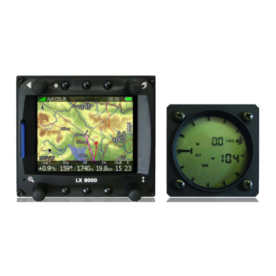
- Page 1 LX8000 Variometer and GPS-Navigation System Version 0.96 LX navigation d.o.o. • Tkalska 10, 3000 Celje, Slovenia • tel +386 3 490 46 70 fax +386 3 490 46 71 support@lxnavigation.si • www.lxnavigation.si...
-
Page 3: Table Of Contents
Flight recorder 5.1.3 Vario parameters 5.1.4 Display 5.1.5 Files and transfers 5.1.5.1 Uploading user airspace and waypoints 5.1.5.2 Uploading LX navigation Airspace and Airports database 5.1.5.3 Managing airspace 5.1.5.4 Managing waypoints 5.1.5.5 Managing airports 5.1.5.6 Managing flights 5.1.5.7 Formatting SD Card 5.1.6... - Page 4 LX8000 version 0.96 April 2008 5.1.6.4 Glider and track 5.1.6.5 Optimization 5.1.6.6 Task 5.1.6.7 Flarm 5.1.7 Sounds 5.1.7.1 Audio settings 5.1.7.2 Voice 5.1.7.3 Alarms 5.1.8 Observation zones 5.1.9 Optimization 5.1.10 Warnings 5.1.10.1 Airspace warnings 5.1.10.2 Altitude warning 5.1.10.3 Flarm warnings 5.1.11...
- Page 5 LX8000 version 0.96 April 2008 5.7.6 Loading task 5.7.7 Moving task point Variometer and Altimeter Smart Vario description Altimeter 6.2.1 IGC barogram recalibration procedure Speed command Final glide calculation Flying with LX8000 On the ground 7.1.1 Power on procedure 7.1.2 Profile selection 7.1.3...
- Page 6 LX8000 version 0.96 April 2008 Page 6 of 85...
-
Page 7: Important Notices
April 2008 1 Important notices LX8000 system is designed for VFR use only as an aid to prudent navigation. All information are presented for reference only. Terrain, airports and airspace data are provided only as an aid to situational awareness. -
Page 8: Packing Lists
LX8000 version 0.96 April 2008 2 Packing lists 2.1 LX8000 with Flarm option • LX8000 digital unit • LX8000 vario unit • Main power cable for digital unit • Cable for vario unit • LX5PC cable (for Flarm update) •... -
Page 9: Basics
320x240 pixels are fitted. For user friendly data exchange an integrated SD card or USB interface is used. The LX8000 has, as an option, a built in flight recorder according to the last IGC specification for all flights. Optionally FLARM collision avoidance system is integrated in LX8000 digital unit. -
Page 10: Vario Unit Features
3.1.4.1 Internal options If ordered, integrated Flarm electronics can be built in to the LX8000 digital unit. All necessary connectors are available on the rear side of the unit (Flarm external indicator, Flarm antenna), which guaranties minimum the same comfort like using of original Flarm devices. -
Page 11: Technical Data
380 mA - maximum brightness without audio and options • 390 mA - maximum brightness without audio and options and with Flarm option • 70 mA – additional for LX8000 vario unit • Cut-out dimensions of LX 8000 digital unit 93.5x81.5mm, outline dimensions: 98x88x115mm inclusive connector •... -
Page 12: System Description
4.1.2 Rotary knobs LX8000 has four rotary knobs. Each of them has one function. Only the zoom knob has, in some cases, a function other than zoom. With the upper left rotary knob the volume can be adjusted. The upper right rotary switch is the mode selector (It changes the mode of the operation). -
Page 13: Switching On The Unit
April 2008 4.2 Switching on the unit After a short press of the power-on button the LX8000 vario unit will turn on. A few seconds later the LX8000 digital unit welcome screen will appear. First screen shows the version of the boot loader, and then the version of the Linux kernel operating system is shown and then the version of the file system. -
Page 14: Text Edit Control
LX8000 version 0.96 April 2008 4.3.1 Text edit control Text editor is used to input alphanumeric string of arbitrary length; picture below shows typical options when editing text. Use bottom-right knob to change value at the current cursor position. Press CHAR>> button to advance cursor to next position. Cursor can also be moved to next position using bottom-left knob. -
Page 15: Selection Control
LX8000 version 0.96 April 2008 4.3.4 Selection control Selection boxes, also known as combo box on Windows operating system, are used to select a value from list of predefined values. Use page selector to iterate through list. 4.3.5 Checkbox and checkbox list Checkbox enables or disables particular parameter. -
Page 16: Switching Off
Method 3 When button with off symbol is pressed for more than 8 seconds, LX80000 will unconditional shutdown. This method is recommended only in case that LX8000 program hangs and it is not possible to shutdown with methods 1 or 2. -
Page 17: Operating Modes
LX8000 version 0.96 April 2008 5 Operating modes The LX8000 has 7 modes or main menus. All of them are selectable by rotating the upper- right knob, which is also called MODE selector. The diagram below shows the mode structure of LX8000. -
Page 18: Setup Mode
0 to arrive on safety altitude. 5.1.1.3 Magnetic variation LX8000 has a built in an Earth magnetic field model. If check Auto variation is selected, then magnetic variation is derived from this model, otherwise user can enter custom value. 5.1.1.4 ETA/ETE calculation based on. -
Page 19: Soaring Start
5.1.2 Flight recorder LX8000 digital unit has built in a fully approved flight recorder by the IGC (A sub-committee of the FAI.) and will produce secure flight records that are acceptable for all FAI requirements including world records. (Note: as at April 08 approval is in progress) Select recording interval, enter pilot name. -
Page 20: Vario Parameters
The external switch wired to LX 8000 AU has absolute priority and will override all other switching methods. 5.1.4 Display Display menu controls screen brightness. LX8000 has an ambient light sensor which detects ambient light and automatically increases or reduces brightness of screen. Page 20 of 85... -
Page 21: Files And Transfers
5.1.5.2 Uploading LX navigation Airspace and Airports database LX navigation is distributing free of charge airport and airspace database for the whole world. Airport and airspace database is maintained by LX navigation only and cannot be modified by user. Latest version of database can be found on http://www.lxnavigation.si/avionics/downloads/databases.cfm... -
Page 22: Managing Airspace
Database is distributed as single file with .ASAPT extension. Copy this file to SD Card or USB stick. Plug SD card or USB stick into LX8000 and select Update database menu item. If more ASAPT files are found on SD card a dialog to select the appropriate one will be shown. -
Page 23: Managing Waypoints
LX8000 is capable storing much more than 1000 hours of flight logs. If SD card or USB stick is inserted in LX8000, flights can be copied to it, when appropriate button is pressed. Flights can be removed using DELETE button. -
Page 24: Graphics
Terrain can be rendered in three different levels. Higher level means more details. LX8000 is optimized to work with high terrain quality. If off option is selected, no terrain will be shown, only water bodies, roads, railways and cities. -
Page 25: Airspace
LX8000 version 0.96 April 2008 5.1.6.2 Airspace In this dialog, you can setup airspace map presentation. Check Show airspace item to enable airspace displays in navigational pages. If item is unchecked, no airspace will be displayed. In the Type panel you can setup how each airspace type is displayed. You should setup each type of airspace zones separately. -
Page 26: Glider And Track
Frequency will display point frequency, if available. 5.1.6.4 Glider and track LX8000 can show colorized path flown, current track vector and target vector with terrain collision warning. Check show path item, if you want to see flown path. Path length defines, how much of flown path will be shown. -
Page 27: Task
5.1.6.7 Flarm Some LX8000 are equipped with FLARM module. If you instrument is equipped with FLARM module, this menu will let you to modify presentation of Flarm radar display. Flarm radar is not available if competition mode is switched on or privacy is switched on. -
Page 28: Sounds
LX8000 version 0.96 April 2008 Checking show Flarm object will enable display of aircraft detected by FLARM. Colors are designed to present three values. The color for aircraft more than 100 meters above your current altitude is defined by the above color item. The color for aircraft more than 100 meters below your current altitude is defined by the below color item. -
Page 29: Voice
With checking of particular message item LX8000 will generate an alarm at the time of event. To avoid repeating alarms for the same event, delay for next alarm of the same type can be set in Don't warn me for next control. -
Page 30: Observation Zones
LX8000 version 0.96 April 2008 5.1.8 Observation zones This menu defines default observation zone geometry. The following items can be chosen: start zone, turnpoint zone, finish zone and templates Each type of observation zone is defined with two angles, two radii and direction. Using these parameters enables the creation of any known zone geometry separately for start, turn point and finish. -
Page 31: Optimization
5.1.9 Optimization During flight LX8000 is optimizing flown path according to OLC or FAI rules. Use this dialog to change way instrument calculates optimization Number of points defines type of optimization. Use five for OLC optimization. It will take into account also reduced distances for last two legs. -
Page 32: Airspace Warnings
LX8000 version 0.96 April 2008 5.1.10.1 Airspace warnings Airspace warnings are the most complex ones. Airspace warning is activated by two triggers: First warning (orange) will be given when a projected position of flight for period, which is defined in Time item, is computed to cross airspace zone. -
Page 33: Flarm Warnings
Altitude warning can be dismissed for 1 minute, 5 minutes or disabled. 5.1.10.3 Flarm warnings Flarm warnings will be raised only when FLARM module is built in LX8000. Using this dialog user can define which data will be presented by LX voice module. 5.1.11 Units Use this dialog to setup units, UTC time offset and type of ballast input. -
Page 34: Hardware
When pilot is flying in lot of different locations. A separate profile for each location can be created. (Example: France, Spain, Namibia, WGC2008) Active profile is selected, when LX8000 is powered on. (See chapter 7.1.2) Use this dialog to add new profile, delete profile, change name for existing profile and activate. - Page 35 Prandtl tube might help. SC switch The LX8000 has an input for an external speed command switch, which is wired to LX8000 vario unit. Using the external switch it is possible to switch between SC and Vario manually.
-
Page 36: Indicator 1 - Indicator 4
April 2008 Temperature offset The LX8000 is supplied with an external outside air temperature (OAT) sensor. With offset setting it we will correct static error of temperature measurement. There is another input called VARIO PRIORITY. When this input is activated by grounding the appropriate wire, the unit will change over to Vario immediately. -
Page 37: Compass
(NN altitude in ft), Flight levels. 5.1.13.3 Compass When compass is connected to LX8000 it is crucial for it operation to make a calibration. See chapter 9.2 for more detail about installation of compass and it calibration Page 37 of 85... -
Page 38: Flarm
Competition mode is prepared only for competition. If that mode is enabled, pilot will not be able to see any Flarm data on LX8000 map. Status of competition mode is recorded in IGC file and can be checked during scoring. -
Page 39: Polar And Glider
LX8000 version 0.96 April 2008 5.1.14 Polar and Glider Use this dialog to enter glider polar and other glider properties. As default polar a glider of standard class is selected. Polars for most of modern gliders are already prepared. Press LIST button and dialog with list of all available glider will be shown. -
Page 40: Password
55556 will enable Condor simulator input via PC port • 55557 will enable Condor simulator input via IGC port • 89891 code is used to initiate firmware update procedure • 99999 will erase all flights stored on LX8000. Page 40 of 85... -
Page 41: Information Mode
Duplicates are automatically removed. If target with nearly same latitude and longitude is found in LX navigation’s Airports database and user waypoint file, user waypoint file will be displayed. -
Page 42: Statistics Mode
5.4.1 Logbook If SD card or USB stick is inserted into LX8000, user can copy selected flight to SD card or USB stick. Select desired flight using bottom-right knob then press appropriate button. Flight is automatically copied to SD card and/or USB stick, if it is inserted in LX8000, when message Calculating security is displayed. -
Page 43: Airport Mode
LX8000 version 0.96 April 2008 5.5 Airport mode Using bottom-right knob you can iterate through different pages. There are four navigational pages available at the moment. 5.5.1 First navigation page Battery GPS status Mode and Relative Local time status target name... -
Page 44: Thermal Assistant
LX8000 version 0.96 April 2008 5.5.1.2 Thermal assistant During thermalling the wind symbol will also shows thermal assistant. Thermal assistant continuously analyzes the thermal when circling. The size of dots indicates strength of thermal. Big dots mean stronger lift at that point. On left or right side of circle, a small airplane symbol is shown. -
Page 45: Third Navigation Page
LX8000 version 0.96 April 2008 5.5.3 Third navigation page Third page has no graphics. Additional to data on previous pages internal pressure sensor altitude is shown. OAT is outside temperature and battery is showing current voltage. 5.5.4 Fourth navigation page Fourth navigational page has also no graphics. -
Page 46: Select An Airport
A message “Event marked” will be shown on screen. • Off will switch of instrument. Message LX8000 switching off will be displayed. LX8000 can also be powered off, if upper left button is pressed for long time, until message “switching off” is shown. 5.5.5.1 Select an airport Selecting airport is very straightforward. -
Page 47: Maccready, Ballast And Bugs Setting
LX8000 version 0.96 April 2008 Press CHAR>> button and cursor will move to second letter. Use bottom-right knob to select second letter. If you want to return to first letter, turn left-bottom knob. Repeat procedure until your desired airport is selected. Press GOTO button and you will be navigating to it. -
Page 48: Wind
5.5.5.4 Wind LX8000 constantly calculates winds using four different methods. Speed difference method is used during circling and is taking into account ground speed difference in single circle. Position drift is calculating wind based on position drift during circling. Minimum three circles must be done to get first wind measurements. -
Page 49: Airspace
LX8000 version 0.96 April 2008 Wind profile is shown on left side of dialog. Yellow color altitude indicates our current altitude. Using bottom-left knob you can scroll wind layers up and down. If new direction is entered to direction spin all wind directions in range from start altitude to end altitude will be modified. -
Page 50: Waypoint Mode
Select this option, if you want to add new waypoint to active waypoint file. If no waypoint file is selected, new waypoint file will be created with name default.cup. A message, copy from airport is displayed first. Press YES, if you would like to copy it from LX navigation Page 50 of 85... - Page 51 LX8000 version 0.96 April 2008 Airports database. An airport select dialog will be opened. Select airport you would like to copy. If no is selected, blank edit dialog is opened. Minimum data that must be entered is name, latitude and longitude. Press CLOSE button to finish editing waypoint properties.
-
Page 52: Task Mode
LX8000 version 0.96 April 2008 5.7 Task mode Task navigation mode is used for task manipulation. Navigation in this page is done exclusively to selected turnpoints. A task can be created only from waypoints stored in active waypoint file. A task can be loaded from tasks stored in active waypoint file. -
Page 53: Task Edit
Event is used to log an event. Recording rate will be increased to 1 second for one minute. A message “Event marked” will be shown on screen. • Off will switch of instrument. Message LX8000 switching off will be displayed. 5.7.1 Task edit Press EDIT action and task edit dialog will open. -
Page 54: Creating Task
MOVE DN is used to move selected point downwards in task 5.7.2 Creating task Make sure at least one waypoint file is loaded into LX8000. It is checked and marked as active waypoint file. See chapter 5.1.5.1 for more details how to upload waypoint file to LX8000 Select task time and press EDIT button. -
Page 55: Modifying Zones
LX8000 version 0.96 April 2008 Repeat procedure until your desired point is selected. Press SELECT button to complete to complete selection. If you do not know exact name of point, which is very unlikely, then just select first letter and press SELECT button. Now scroll to desired point using bottom-right knob. -
Page 56: Task Options
Check “Finish is 1000m below start”, when you are making a badge or record flight. If this option is checked, LX8000 will not navigate you to finish point elevation, but to altitude, which is going to be 1000m below start altitude. -
Page 57: Moving Task Point
LX8000 version 0.96 April 2008 Total task distance, task description and task points are shown for each task stored. Select desired task rotating bottom-right knob and press LOAD. Task will be loaded into active task and task edit dialog will be opened. -
Page 58: Variometer And Altimeter
LX8000 version 0.96 April 2008 6 Variometer and Altimeter All signals from the pneumatic sensors (altitude, speed) are derived from high quality pressure sensors which mean that no flask is necessary. The vario signal is derived from the altitude signal. All signals are temperature and altitude compensated. A custom programmable LCD has been designed to display the vario information as well as many other parameters. -
Page 59: Altimeter
0.5 to 5 1 to 4 or OFF 6.2 Altimeter The altimeter of LX8000 is temperature compensated from -20ºC up to + 60ºC. The altimeter is calibrated from 0 to 6000m (20,000ft), but indication goes up to 8000m (26,000ft). 6.2.1 IGC barogram recalibration procedure LX8000 has an additional pressure sensor for altitude recording. -
Page 60: Flying With Lx8000
April 2008 7 Flying with LX8000 To get the best out of the LX8000, it is important that some preparation is done prior to the takeoff. Trying to configure the instrument or set a task while flying is very hazardous, especially on competition or at least it could spoil your whole day! Pre-flight preparation will ensure that the flight will be both safe and enjoyable. -
Page 61: Preflight Check
7.1.4 Preflight check After elevation setup, LX8000 will get in airport mode. It will take about 30seconds to draw map screen for first time. All waypoint files and databases are loaded at that time and therefore instrument might react a little bit slowly. -
Page 62: Assigned Area Tasks (Aat)
LX8000 version 0.96 April 2008 Compared to LX7007 there is no option to declare a task. There is one and only task. This task is going to be automatically declared in IGC file on take off. Task can also be modified during flight, but changes are not going to be written to IGC file. - Page 63 LX8000 version 0.96 April 2008 Page 63 of 85...
-
Page 64: Performing The Flight
LX8000 version 0.96 April 2008 Usually task sheet with observation zone definitions matching LX8000 observation zone definition will be given. An example of task sheet is given in previous picture. However, when assigned area is defined only with two radials and two radiuses some calculation must be accomplished. -
Page 65: Over Turnpoint
If button NEXT is pressed task is advanced to next turnpoint. When flying in assigned area it is NOT important when you will advance to next turnpoint. LX8000 is always taking into account most optimal fix inside assigned area for total distance calculation. -
Page 66: Procedure After Landing
If SD card or USB stick is inserted at this moment, flight will automatically be copied to it. Please use regular methods to power down LX8000. See chapter 4.4 for more details. It is important that LX8000 is switched off using software. Never power down LX8000 using main power switch. -
Page 67: Installation
The LX8000 digital unit is installed in an aperture 93.5mm width and 81.5mm height The LX8000 vario unit and any additional vario indicators need a standard 57mm cut-out each. Three pressure connectors are fitted to the back of the LX8000 vario unit. A label shows their functions. •... -
Page 68: Mounting Lx8000
If a short circuit happens then the 57 mm unit will not work any more, but the reason is not the defect of 57mm unit, but hot automatic fuse. Turn off the LX8000 system and wait for the automatic fuse to cool down. - Page 69 LX8000 version 0.96 April 2008 Page 69 of 85...
-
Page 70: Ports And Wiring
LX8000 version 0.96 April 2008 8.3 Ports and Wiring GPS antenna Network connector Flarm HF Flarm external DO NOT USE IT! antenna indicators, splitters Main power supply (LX8000DU USB memory stick Colibri Flight wiring) Connector to USB1 port recorder Page 70 of 85... - Page 71 LX8000 version 0.96 April 2008 Page 71 of 85...
-
Page 72: Options
(telephone type) delivered with the unit. Use connector on the back side of the LX8000 marked FLARM. The unit is powered from LX8000. Delivered is an external display developed by LX navigation, which is slightly adapted to work with LX 8000. - Page 73 The external displays produced by LX navigation will change over to Demo mode after MODE button is pressed briefly 10 times. Nearest mode and all possible warnings will then be displayed.
-
Page 74: Lx Flarm Graphic Display
If two units work in parallel (double seater) one unit must be PIC and another PAX. 9.1.1.2 LX Flarm graphic display This type of display is 100% compatible with LX8000 Flarm output and may be used instead of LED version. See manual for details. 9.1.1.3 LX Flarm display 57 mm This unit is standard 57mm unit and replaces LED version also. -
Page 75: Functional Check After Installation
LX navigation offers a suitable box. 9.1.3 Functional check after installation After LX8000 has been switched on the Flarm External Indicator will receive power and will pass initial routine which will take several seconds. Description of LED statuses: 1. -
Page 76: Error Messages
After installation obligatory check functionality from 2 to 3 and 11. 9.1.4 Error messages After Flarm failure has been detected, LX8000 will show this situation after booting and the routine Flarm self test is not OK. 9.1.5 Flarm traffic information on moving map All Flarm equipped gliders in range will be shown on moving map as small aircraft symbols, whether or not they cause a collision warning or not. -
Page 77: Uploading Obstacles
On LX8000 enter password 41000 When recover is finished press OK button. 9.1.7 Uploading obstacles Run Flarm tool and select communication port. Connect LX8000 via PC cable with your PC Go into password menu and enter password 42000 Page 77 of 85... - Page 78 LX8000 version 0.96 April 2008 When finished, press OK button on LX8000. Page 78 of 85...
-
Page 79: Compass Module
The compass module is an electronic compass device (magnetic field sensor), which was developed for the LX8000. The LX8000 recognizes the compass module automatically when it is coupled onto the RS485 bus. The only configuration settings needed relate to the compensation procedure. -
Page 80: Installation Of The Compass Module
LX8000 version 0.96 April 2008 Wind True airspeed and true heading Ground speed and ground track The angular difference between HDG and TRK depends on the magnitude of the wind vector and is normally quite small which means that the measurement has to be quite precise if accuracy is to be achieved. -
Page 81: Adjusting The Compass Module
LX8000 version 0.96 April 2008 9.2.4 Adjusting the compass module The compensation of the compass is done in the setup/hardware/compass 1. Orientate the glider to 360°. N label will be automatically focused 2. Stabilize reading and press SET to save correction for this direction 3. -
Page 82: Final Check
When the final test is satisfactory, your LX8000 is ready to calculate the wind with the compass method. The calibration is specific for your combination of aircraft and compass, which means you, can not transfer the compass to another aircraft while using the same calibration values. -
Page 83: Stick Handle With Keys
LX8000 version 0.96 April 2008 9.3.1 Stick handle with keys The original stick grip should be removed and replaced with the new one. On the top of the new grip there are 9 push buttons. An additional button positioned on the front side is for climb/cruise change over. -
Page 84: Revision History
LX8000 version 0.96 April 2008 10 Revision history April 2008 Initial release of owner manual Page 84 of 85...
Need help?
Do you have a question about the LX8000 and is the answer not in the manual?
Questions and answers