Table of Contents
Advertisement
Quick Links
Advertisement
Table of Contents

Related Manuals for LX Navigation LX10K


Summary of Contents for LX Navigation LX10K
- Page 1 LX10K user’s manual...
- Page 2 Device manual - LX navigation - July, Tkalska ulica Celje Tel.: Fax.: info@lxnavigation.com www.lxnavigation.com...
-
Page 3: Document Information
Document status Document status: PUBLIC Document status Explanation Internal Intended only for LX navigation staff Public Available publicly to all Personal Intended for a speci c person and/or company, noted on this page Dealer... -
Page 4: Table Of Contents
Document name: CONTENTS Document revision: Contents Document information Abstract ......... . Document status . - Page 5 Document name: CONTENTS Document revision: Nearest landable navigation page ......8 GPS DATA INVALID ....... Thermal assistant page .
- Page 6 Document name: CONTENTS Document revision: 6 Connectivity WiFi connectivity ........6.
- Page 7 Document name: CONTENTS Document revision: . . . Battery status indicator ......8 LX Joy Taking care of your LX The internal battery .
-
Page 8: Important Notices
This device is warranted to be free from defects in materials or workmanship for two years from the date of purchase. Within this period, LX navigation will, at its sole discretion, repair or replace any components that fail in normal use. Such repairs or replacements will be made at no charge to the customer for parts and labour, the customer shall be responsible for any transportation cost. -
Page 9: Sunburned Display
Some countries do not allow the exclusion of incidental or consequential damages, so the above limitations may not apply to you. LX navigation retains the exclusive right to repair or replace the unit or software, or to offer a full refund of the purchase price, at its sole discretion. -
Page 10: Getting Started
Document name: Getting started Document revision: Getting started Device overview The LX k is a glider vario-navigation system, that comprises of two devices. The main unit - the LX k, which is always in the 8 mm ( /8 inch) size and the vario indicator. The vario indicator comes in three different options: •... - Page 11 Document name: Getting started Document revision: An integral IGC approved ight recorder with ENL level detector will record the ight to internal solid-state memory ( 6GB). All ights can be copied to an external SD card after ight. The LX k has terrain information of the complete world.
- Page 12 Document name: Getting started Document revision: • Complete TP/APT/TSK, NRST navigation with airspace information and warnings • Highest level IGC approved ight recorder ( nd the IGC approval here) • Flarm radar screen • Thermal assistant screen • System extensions: Second seat con guration, Remote control operation (LX Joy) •...
-
Page 13: Basic Operation
Once the device is turned on, a sequence of screens will appear in the following order: • LX navigation greeting screen • Second screen stating the device type, serial number, IGC number and rmware version • The initial setup page will appear, where basic information is selected: –... -
Page 14: Device Interface
Document name: Basic operation Document revision: Device interface The LX k features two push buttons and two push-rotary knobs for pilot-device communi- cation. The front side of the device, represented by gure , shows the LX k’s user input interface. Figure . -
Page 15: User Input
Document name: Basic operation Document revision: User input The LX k was envisioned to be simple and intuitive to use. There are two buttons and two push-rotary buttons mentioned in the previous sub-section. The LX k can also be commanded by an LX Joy. Learn more in the LX Joy section of this manual. -
Page 16: Performing An Update
In order to be on track with the latest software releases, be sure to regularly follow our Database webpage. Once you nd an update, contact LX navigation support via the following email: info@lxnavigation.com with your contact details, device type, the software version you would like to update to and the serial number of your device. -
Page 17: Turning The Lx K Off
Document name: Basic operation Document revision: Turning the LX k off The LX k can be turned off in different ways, depending on the con guration you have. All units will start the shutdown process once the power supply is cut from the main power lines, unless in ight mode. - Page 18 Pitot-static system, or similar. LX navigation is in no case liable for any damages that may appear when simulating and strongly discourages simulating ight mode while grounded.
-
Page 19: Advanced Operation
Document name: Advanced operation Document revision: Advanced operation Primary pages overview This section will cover the complete specter of operations possible on LX k’s primary pages. There are primary pages on the LX k. You can scroll between these pages by using the right push-rotary knob (PAGES). - Page 20 Document name: Advanced operation Document revision: Pressing the Right push button will open the MC (MacCready) sub-page on the volume parame- ter. Pressing the right push button again will change to the next MC parameter, in the following order: • Volume >...
- Page 21 Document name: Advanced operation Document revision: direction of your movement, your track, and the second one is showing the direction to your chosen turnpoint, the destination line. Colours can be changed in the Graphics setup menu. On the map, a red/blue line, known as the TAIL is drawn behind the glide, marking your pre- vious positions.
- Page 22 Document name: Advanced operation Document revision: . . . The Final glide indicator The Final glide indicator is an indicator located opposite of the wind indicator, on the far right of the map, above the NavBox line. It displays the Final Glide for the set MC value. The MC value is displayed above the Final Glide value, in white lettering.
- Page 23 Document name: Advanced operation Document revision: IGC altitude - altitude displayed by the internal IGC pressure sensor, which is not offset by QNH changes. Density altitude - the density altitude is the altitude relative to standard atmospheric conditions at which the air density would be equal to the indicated air density at the place of observation. GPS altitude - altitude displayed by the internal GPS module.
- Page 24 Document name: Advanced operation Document revision: Flap position - current ap position. Requires the LX Flap sensor for operation. Rec. ap position - shows the recommended ap position, as de ned by yourself in the Glider sub-section..Status indicators Flarm status Is represented with a red Flarm symbol, depicted with Flarm status indicator icon.
- Page 25 Document name: Advanced operation Document revision: Battery status White battery outline indicates the device is running on external power, while a red battery out- line indicates the device is running on internal power. Figure red bar Figure yellow bars Figure green bars (less than .8V)
- Page 26 Document name: Advanced operation Document revision: Turnpoint navigation page This page is used for navigating towards a single turnpoint, from the .cup le, loaded into the k. The navigation screen shows turnpoints, airports, airspaces and ground elevation on the map. Figure 8.
- Page 27 Document name: Advanced operation Document revision: Figure . Turnpoint additional info Choosing Name or Code will open up the Filter setting, where you can type the name or code lettering. Choosing a turnpoint will set the turnpoint as the navigation point for the turnpoint navigation page.
- Page 28 (.cup) and airport (.af) les installed. Some of these, like .cup and .cub les, are available on competitions, from club managers, or governing national air bodies (like DAeC), while other, like the .af le, are provided solely by LX navigation. NOTE Files provided by LX navigation (.cub and .af) can be found on...
- Page 29 Document name: Advanced operation Document revision: Airport navigation page The Airport navigation page is set up in much the same way as the Turnpoint navigation page, so be sure to check the previous section for additional information. This page is used for navigating towards a single airport, from the .af le loaded into the LX k.
- Page 30 Document name: Advanced operation Document revision: Pressing the left push-rotary knob will open the APT info sub-page, showing Bearing, Distance, Final glide, Elevation, Airport Frequency and Runway directions. Pressing the right push-rotary knob you will enter the ’Select airport’ sub-page. Here, a selection of airports will be shown, along with distance and bearing, as well as steering course (relative bearing) as described earlier, with an arrow.
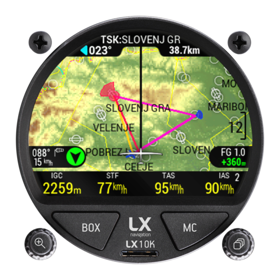
- Page 31 Document name: Advanced operation Document revision: . .6 Task navigation page This page is intended for task navigation. A task can be made using turnpoints, airports or a combination of both. It can be uploaded a third party device via Bluetooth as a declaration, downloaded from the web, created on the device, or loaded from the .cup le.
- Page 32 Document name: Advanced operation Document revision: • Export task - Task will be exported to your external microSD card in a .cup le format, containg only the task, without any additional turnpoints, enabling easy sharing between devices. Figure 6. Task options sub-page Pressing the right push-rotary knob will open the ’Edit task’...
- Page 33 Document name: Advanced operation Document revision: • Start (S) - The starting point of your task • n-number of intermediate points • Finish (F) - Finish line • Landing (L) - Does not have to be set, is navigated to after the nish line has been passed, can not be deleted By default, the task edit page shows only four points: Take-off, Start, Finish and Landing.
- Page 34 Document name: Advanced operation Document revision: NOTE When choosing the ’Fin. m below’ option, keep in mind that the reserve altitude is also taken into account for nal glide calculation, which means the nal glide will be calculated higher than needed, as an additional layer of reserve. The nish point has an additional option of setting the ’Finish altitude’.
- Page 35 Document name: Advanced operation Document revision: Figure . View zone option Figure . View zone page NOTE Choosing the ’Go to’ option in the Edit task sub-page on a navigation page will set the selected point as the current navigation point on your Task navigation page. NOTE The quickest way to set up the task on the LX k is to rst set the list of...
- Page 36 Document name: Advanced operation Document revision: Nearest landable navigation page The Nearest landable navigation page (NRST) is the simplest of the four navigation pages. This page always navigates to the nearest landable point. This landable point can be either an airport from the .af le or a turnpoint, marked as a landable, from the active .cup le.
-
Page 37: Gps Data Invalid
(.cup) and airport (.af) les installed. Some of these, like .cup and .cub les, are available on competitions, from club managers, or governing national air bodies (like DAeC), while other, like the .af le, are provided solely by LX navigation. NOTE Files provided by LX navigation (.cub and .af) can be found on... -
Page 38: Thermal Assistant Page
Document name: Advanced operation Document revision: Thermal assistant page The Thermal assistant page is a pilot’s best friend while thermalling. It is designed to provide the pilot with all relevant information while in a thermal. The TA page incorporates four NavBoxes, showing the following parameters: •... - Page 39 Document name: Advanced operation Document revision: helping him center. A glider represents the pilot’s current position in the thermal. The glider can be either on the left side (circling to the right), or the right side (circling to the left) of the Wind indicator. Next we see dots forming a circle, at 8 degree intervals.
-
Page 40: Flarm Radar Page
Document name: Advanced operation Document revision: Flarm radar page The Flarm radar page shows all surrounding objects reported to the LX k by a Flarm device. If the said Flarm device has an ADS-B module, the LX k will show ADS-B objects as well. Flarm objects are shown on a radar screen with track-up orientation. - Page 41 Document name: Advanced operation Document revision: Figure 8. List of visible Flarm objects Figure . Additional options for objects An important safety feature of the LX k is the Flarm warning page. This page pops-up whenever the Flarm device sends a warning sentence, regardless of the menu, page or setup you’re currently in.
- Page 42 Document name: Advanced operation Document revision: The LX k can show the following objects with appropriate graphics: • Unknown - • Drop plane - • UFO - • Glider - • Balloon - • Hang-glider - • Tow plane - •...
-
Page 43: Ahrs Page
Document name: Advanced operation Document revision: AHRS page The AHRS page utilizes the LX AHRS module in order to provide the pilot with important ight parameters. The LX AHRS module is required for the use of AHRS page. Figure . Attitude indicator on PFD page The AHRS page offers the pilot the following ight parameters: •... - Page 44 Document name: Advanced operation Document revision: Bank scale - the inverted white triangle indicates zero on the bank scale. Major tick marks at ° and 6 ° and minor tick marks °, °, and ° are shown to the left and right of the zero. Angle of bank is indicated by the position of the pointer on the bank scale.
-
Page 45: G-Force Page
Document name: Advanced operation Document revision: G-force page This page utilizes the LX k’s internal inertial platform for showing the current, maximum and minimal G-loading during a ight, both numerically and graphically. The page also shows the IAS sliding tape, TAS, altitude sliding tape and QNH, as depicted on the Thermal assistant page. Your current G-load is shown graphically with a red dot. - Page 46 Document name: Advanced operation Document revision: Figure . Airplane axis and the Y-Z plane Device manual Public...
-
Page 47: Info Page
Document name: Advanced operation Document revision: .6 Info page The info page shows the current GPS status and additional info, received from the GPS, like the GPS location, UTC time and date. The device shows the battery voltage of both the LX k’s internal battery and the external (airplane) battery. -
Page 48: Logbook/Flight Statistics Page
Document name: Advanced operation Document revision: Logbook/Flight statistics page This page can be either the ’Logbook’ or ’Flight statistics page, based solely on if the device is in ight mode. Additional info on ight mode can be found in sub-section A word on internal battery and ight mode. -
Page 49: Flight Statistics
Document name: Advanced operation Document revision: Figure . List of ights in the logbook Figure 8. Flight details in the logbook Flight statistics Once the device enters ight mode, which is explained in detail in sub-section A word on internal battery and ight mode, the Flight statistics page appears. Figure . - Page 50 Document name: Advanced operation Document revision: NOTE Once the LX k determines that you are not in ight, it will start the minute countdown to nishing your ight. Once the countdown has nished, it will calculate the security and save the .igc le to its internal memory. The conditions for nishing a ight are: •...
-
Page 51: Airspace Page
Document name: Advanced operation Document revision: .8 Airspace page The ’Airspace’ page is intended for informing the pilot of the airspace surrounding him. The LX k looks up all airspace in the vicinity of the pilot’s current location and lists them in regards to distance. -
Page 52: Setup Page
Document name: Advanced operation Document revision: Setup page The Setup page, or Setup menu will be processed in the Device setup section. Figure . Setup page Device manual Public... -
Page 53: Device Setup
Document name: Device setup Document revision: Device setup This section will go through the complete setup process for the LX k variometer. It is im- portant to note that the Setup menu is divided into two sections - the User and System settings. All of the settings in the User sub-part of the Setup menu are saved to a speci c Pilot pro le and change, when a pilot pro le is changed. - Page 54 Document name: Device setup Document revision: The Pilot sub-menu holds all of the pilot and copilot related information. Each pilot pro le is at the same time the user pro le to which all user settings are saved to, as discussed in the introductory part of the Device setup sub-section.
- Page 55 Document name: Device setup Document revision: Vario/SC The Vario/SC setup sub-menu is used for setting all vario-related parameters and holds the following settings: • Altitude Sensor - lets you choose which sensor will be used for determining your current altitude. The LX k has two static pressure sensor, an internal - the IGC pressure sensor, and an ’external’...
-
Page 56: Task
Document name: Device setup Document revision: Task The Task setup sub-menu is used for setting up the default sectors for turnpoints to be used, when a new task is created. The sub-menu holds the following settings: • Default start - sets the default starting sector parameters •... - Page 57 Document name: Device setup Document revision: Figure . Four indicators on a white back- Figure 6. Two indicators on a black back- ground theme ground theme The following digital numerical indicators are available: • Empty • True track • Current ef ciency •...
- Page 58 Document name: Device setup Document revision: Vario netto - the actual vertical speed of the surrounding air mass. Is calculated by adding the current vertical speed indicated by the variometer, and the sink rate of the glider at that speed. Sink rate of the glider is calculated from the polar.
-
Page 59: Voice
Document name: Device setup Document revision: Voice The Voice setup sub-menu holds the volume and mixer options for voice warnings, as well as a list of available voice warnings to choose from. • Volume • Mixer • Flarm traf c •... - Page 60 Document name: Device setup Document revision: . . . Airspace The airspace sub-menu holds the settings for colour and transparency of the ll and outline for the following airspace types: • Controlled zone • Military • Prohibited • Other • Restricted •...
- Page 61 Device setup Document revision: Figure . Color Palette Figure 8. Color Palette Figure . Color Palette - LX Navigation - LX Navigation - Imhof Figure 6 . Color Palette Figure 6 . Color Palette Figure 6 . Color Palette - Imhof...
- Page 62 Document name: Device setup Document revision: Figure 6 . Color Palette - White (no elevation) NOTE APT icons are shown on the map up to a zoom level of km. TP icons are shown up to a zoom level of km. At higher zoom levels we are only showing Airspace lines, due to the legibility.
- Page 63 Document name: Device setup Document revision: . . . Theme The Theme sub-menu offer the pilot to choose between themes. The LX k features has two areas for themes - the vario scale and the internal part (everything inside of the vario scale).
-
Page 64: Warnings
Document name: Device setup Document revision: . .8 Warnings The Warnings setup sub-menu gives the pilot an overview of which warnings are available. In the case of this sub-menu, warnings refer to a warning, that is given by the LX k to the pilot in the shape of a red square as shown with the picture below: Figure... - Page 65 Document name: Device setup Document revision: In the past, the event function was used because less internal memory was available for ight logging and consequently less frequent logging intervals were set as standard ( s). When the event button was triggered, the logging changed to the ’Event interval’, thus ensuring your ticking of the sector was captured with a high enough resolution.
-
Page 66: System Settings
Document name: Device setup Document revision: System settings Glider The following glider associated settings can be found in this sub-menu: • Polar - sets the polar by which nal glide is calculated. The LX k has a large and ever- growing selection of glider polars. -
Page 67: Units
Document name: Device setup Document revision: Aircraft icon selection: • Airplane - • Rotorcraft - • Jet - • Gyrocopter - • Glider - • Fighter - • Motor glider - • Airship - NOTE To create a User speci ed polar, go to Setup > Glider > Polar > Select polar and choose the User polar. -
Page 68: Nmea
Document name: Device setup Document revision: NMEA The NMEA sub-menu is used for determining which sentences are being sent out through the User port, Flarm port and the Bluetooth connection. This sub-menu will only explain in small detail what is available and what it is used for. For more information on connectivity, check the Connectivity section. -
Page 69: Inputs
Document name: Device setup Document revision: Inputs The Input setup sub-menu refers to the functionalities of the LX k closely dependant on existence and proper use of the Inputs interface. The inputs interface incorporates slots for external micro-switches, connected to the Input port on the LX k. -
Page 70: Transfer
FlarmNET les. WARNING LX navigation provides database les on an informative level and can in no way be held accountable implicitly, or otherwise, for and damage, be it material, personal or other, that may occur due to the use of this device. -
Page 71: Turnpoints
. . . Turnpoints Turnpoint les, in the .cup le format, are not supplied by LX navigation, but can usually be found at competitions, various webpages or from club manager and club mates. As a starting point, you can check the Open ight maps. You can even create your own turnpoint les either by hand, or using different software. -
Page 72: Load Task
LX navigation database part of webpage, as well as supplied by competition directors, club managers, club mates and other readily available database sources. In order to use a certain airspace le, rst you need to copy it to the LX k’s internal memory,... -
Page 73: Network
Document name: Device setup Document revision: . .6 Network This part of the manual will only go through the settings available in the Network sub-menu part. For information on how to connect to different devices and utilize the LX k’s connectiv- ity capabilities, please check the Connectivity section of this manual. -
Page 74: Localisation
Document name: Device setup Document revision: NOTE If you are connected to a WiFi network, it is displayed under the ’Connected’ list. Pressing on the connected network will make the device disconnect from this network. Localisation Contains information regarding the local settings of the LX k. -
Page 75: Service
Document name: Device setup Document revision: Service The Service setup page contains various device and service related settings, as noted below: • Device info - shows basic information regarding the LX – Serial number – IGC number – Firmware version –... -
Page 76: Club Mode
Document name: Device setup Document revision: . . . Club mode The Club mode is used for setting up Club pilot pro les and editing them. By ’Club’ we mean generic pilot pro les, which are password protected and can only be changed by a ’Club manager’. -
Page 77: Connectivity
Document name: Connectivity Document revision: Connectivity This section will go through how to set up different types of connections. By connections, we mainly mean different means of communication between the LX k and third party devices. WiFi connectivity At this moment, the WiFI connectivity option on the LX k is used solely for sending .igc ights to emails. -
Page 78: Sending The Ight
Document name: Connectivity Document revision: You will now see the icon symbolizing the connecting attempt - and a the shift of the WiFi network name to the ’Connected’ list, if the connection attempt is successful. 6. . . Sending the ight To send a ight, go to the Logbook page, and select the ight you wish to send. -
Page 79: Connecting An Oudie Or Other Pna/Pda Device
• Port - select the port with the same name as your LX k’s Bluetooth name (LX LX xxxx) • Driver - LX navigation (pending) • Passthrough device - Off Once done, you should see the connection state go from ’Not connected’ to ’Connected; Baro;... -
Page 80: User Port Connectivity
• GPRMB • PFLAx • LXWPx Now go to the Oudie’s Menu > Settings > Hardware > Device and select ’LX navigation’ (pending). If you go to the Terminal, you should see communication owing, in the form of NMEA sentences. -
Page 81: Connecting An Oudie
Document name: Connectivity Document revision: 6. . Connecting an Oudie The main bene t of a wired connection between the Oudie and LX k is that the LX k will charge the Oudie, for as long as the LX k has an external power supply. Also, if you wish to connect two Oudies to an LX k, you can do this by connecting one device via Bluetooth and the second device via cable. -
Page 82: Vario Indicator Unit
Document name: Vario Indicator Unit Document revision: Vario Indicator Unit The LX k is a system consisting of two devices. The rst one, the LX k main unit, has been the centre of our attention. This section will turn our attention towards the second device - the Vario Indication Unit. -
Page 83: The Digital Vario Unit
Document name: Vario Indicator Unit Document revision: The digital vario unit The digital vario unit has three main pages: • Main page • Thermal assistant page • Vario setup page The digital vario unit has a single push-rotary knob, labeled with a loudspeaker. This push-rotary is used for commanding the indicator in two ways: •... - Page 84 Document name: Vario Indicator Unit Document revision: Figure . Red digital needle scale Figure 8 . Blue digital needle scale The digital needle scale can be set in the Indicators menu to shown one of the following ight parameters: • Vario •...
- Page 85 Document name: Vario Indicator Unit Document revision: . . . Digital numeric indicators The digital indicator’s main page features either two or four numerical indicators. If two indi- cators are chosen, the info shown is twice as large, which is why this setting is recommended with pilots who have short-sightedness issues.
- Page 86 Document name: Vario Indicator Unit Document revision: . . . Flarm status indicator Is represented with a red Flarm symbol, depicted with Flarm status indicator icon. If the Flarm icon is present, the device has an established connection with a Flarm device. On how to get more info from the Flarm device, check the Info page section.
- Page 87 Document name: Vario Indicator Unit Document revision: . . . Flight mode status indicator The ight mode indicator depicts whether the device is currently in straight ight, or circling mode. The common way to transition between the two modes is by activating the SC (Speed Command) button/switch, or by using one of the automatic ways, implemented into the device.
- Page 88 Document name: Vario Indicator Unit Document revision: The wind is being calculated both in circling and in straight ight. It will update at all times and no settings are required..Volume setting A pilot can change volume in two ways: •...
- Page 89 Document name: Vario Indicator Unit Document revision: Thermal assistant page The Thermal assistant page on the digital vario indicator is very similar to the one already described previously for the main unit. The main difference is the upright orientation of the screen, the lack of the altitude sliding tape and the presence of the vario arc.
- Page 90 Document name: Vario Indicator Unit Document revision: white with a black edge when light theme is used) represents the strongest part of the thermal during your last circle. To the left of the Thermal assistant, we can see a colour arc, indicating IAS. The current IAS is framed, and behind it sliding colour arcs can be seen.
- Page 91 Document name: Vario Indicator Unit Document revision: • Black and white - black center and white needle arc • Black and black - black center and black needle arc • White and white - white center and white needle arc •...
- Page 92 Document name: Vario Indicator Unit Document revision: . . . Thermal assistant This menu holds additional settings for the thermal assistant page for the digital variometer. The setup options for the thermal assistant page is the same as described previously for the main unit.
- Page 93 Document name: Vario Indicator Unit Document revision: The analog vario unit By contrast, the analog vario unit is much simpler, offering only one screen and no settings on the device itself. Figure . Analog vario indicator Volume setting A pilot can change volume in two ways: •...
- Page 94 Document name: Vario Indicator Unit Document revision: Digital indicators The analog indicator’s main page features two numerical indicators. Each of these indicators is formatted in the same way. On the far-left, the name of the indicator is displayed, noting which ight parameter the indicator is showing. Next, with larger fonts, the actual value is shown, with the value unit to the right of the shown value.
-
Page 95: Battery Status Indicator
Document name: Vario Indicator Unit Document revision: . . . Flight mode status indicator The ight mode indicator depicts whether the device is currently in straight ight, or circling mode. The common way to transition between the two modes is by activating the SC (Speed Command) button/switch, or by using one of the automatic ways, implemented into the device. -
Page 96: Lx Joy
Document name: LX Joy Document revision: LX Joy The LX Joy (short for Joystick) is a remote control unit for the LX k, which attaches to the aircraft’s ight control stick. Using the Joy with the LX k, you can access all available settings, without touching the LX k itself. - Page 97 Document name: LX Joy Document revision: The BOX button will mimic the pressing of the BOX button on the LX The ’X’ button will mimic the pressing of the left push-rotary knob on the LX The PTT button is connected to the Radio and does not in uence the LX NOTE The LX k is not compatible with the legacy LX Remote Stick.
-
Page 98: Taking Care Of Your Lx K
Document name: Taking care of your LX Document revision: Taking care of your LX If you were taken here by following the link from the introductory part of this manual, you can get back by clicking on the underlined text - Using this manual. The internal battery The LX k has a Li-Ion internal battery, used for powering the unit, if the main power supply of... -
Page 99: Pressure Sensors
Document name: Taking care of your LX Document revision: WARNING Draining the battery completely will cause the LX k to lose its IGC seal. If this happens, the pilot will be prompted by a red warnings stating ’Seal not valid!’, when powering up the device. -
Page 100: Microsd Card Reader
Document name: Taking care of your LX Document revision: k’s connector may break and get ripped out. One should always be careful when taking the cable out, to press the security pin completely. .6 MicroSD card reader The LX k features a microSD card reader on the front of the device. The microSD should always be inserted carefully, not to miss the internal microSD card reader electronics. -
Page 101: Release Notes
Document name: Release notes Document revision: Release notes • Displaying ”Select from the list” instead of empty eld for Select TP/APT/AS item in Trans- fer menu - 6) • Added Watchdog reset to waypoint sort loop on NRST page (possible x for NRST page crashes) •... - Page 102 Document name: Release notes Document revision: - 6- • Protocol extended with additional navigation and sensor data as requested by LK8 and XC Soar developers - 6- 8) • Added password for formating internal SD • Fix for updating CAN units does not start if maps are disabled in settings. - 6- •...
-
Page 103: Automated Builds (From - 6- To - - 6)
Document name: Release notes Document revision: - 8) • Long update le names enabled. • AHRS page stripe widgets color xed on white theme. • Added ”This list is empty” text to Airspace and Logbook page if list is empty. •... -
Page 104: Version
Document name: Release notes Document revision: • Support for accepting and syncing mail with Zeus. • Adding progress, info and warning messages for different states occurring during send- ing IGC le to email. • Minor graphical xes (menu icons). • Fix for Flarm Net le deselecting on device restart •... -
Page 105: Version
Document name: Release notes Document revision: Version . . • Added progress bar for map loading. • Uni ed look of red cross for invalid data. • General code improvements. • Steering refresh rate improved. • Added con rmation when deleting task. •... -
Page 106: Contact
Document name: Contact Document revision: Contact Headquarters LX navigation d.o.o. Tkalska ulica Celje Slovenia VAT ID Company is registered in Slovenia, EU under the VAT ID: SI Webpage www.lxnavigation.com Phone + 86 ( ) + 86 ( ) Sales sales@lxnavigation.com Support info@lxnavigation.com... - Page 107 LX navigation will not proceed with repair unless we get a straight respond on information email sent aſter inspection of device. LX navigation is not obligated to keep the device, if the owner does not answer the information email within a 30 day period. If the customer respond aſter the given period, some additional charges may appear.
Need help?
Do you have a question about the LX10K and is the answer not in the manual?
Questions and answers