
Related Manuals for LX Navigation LX5000 V9.0


Summary of Contents for LX Navigation LX5000 V9.0
- Page 1 LX5000 V 9.0 Variometer and GPS-Navigation System March. 2002 LX navigation + 386 3 490 4670 + 386 3 490 46 71 support@lxnavigation.si http://www.lxnavigation.si...
-
Page 2: Table Of Contents
LX5000 March 2002 1 Contents CONTENTS................................1 GENERAL ..................................3 ..............................3 ECHNICAL DATA )......................4 OTARY SWITCHES AND KEYS BUTTONS 2.2.1 On/Start key..............................4 2.2.2 Mode selector (rotary switch) ........................4 2.2.3 UP/Down Selector (rotary switch) .......................5 2.2.4 ENTER key ..............................5 2.2.5 ESC/OFF key..............................5 2.2.6 EVENT key ..............................5 2.2.7 MC/ BAL key ..............................5... - Page 3 LX5000 March 2002 3.2.5 TSK (task)..............................30 3.2.5.1 TSK select ................................31 3.2.5.2 TSK edit..................................31 3.2.5.3 Task new..................................33 3.2.5.4 DECLARE................................33 3.2.6 Statistics ..............................34 3.2.6.1 Flight statistics.................................34 3.2.6.2 TSK Statistics ................................34 3.2.6.3 LOG BOOK................................35 3.2.6.4 Statistics after flight..............................35 ..............................37 ARIOMETER 3.3.1 Vario................................37 3.3.2 Altimeter ..............................37 3.3.2.1 IGC barogram recalibration procedure ........................37...
-
Page 4: General
LX5000 March 2002 2 General The instrument consists of two units, the main unit (80 mm) and LCD Vario indicator (57 mm). Additional LCD Vario indicators can be added. The fast calculation processes and graphic displays are achieved by using modern microcontroller technology. The sensors are modern, highly precise, temperature compensated pressure sensors for altitude and speed to eliminate errors Vario functions •... -
Page 5: Rotary Switches And Keys (Buttons)
LX5000 March 2002 2.2 Rotary switches and keys (buttons) The following control elements are mounted on the main unit • Four rotary switches (selectors) • Five keys (push buttons) The LCD-Vario is designed as a slave unit, which means it has no control switches and keys. ON, start key ESC /OFF key ENTER key... -
Page 6: Up/Down Selector (Rotary Switch)
LX5000 March 2002 2.2.3 UP/Down Selector (rotary switch) This rotary switch has a lower priority than the mode selector switch and is active all the time in the selected mode. It is mainly used for selecting sub menus during navigation and to scroll in the edit menu. 2.2.4 ENTER key The main function of this key is confirmation and to start edit procedures. -
Page 7: Operation Modi
LX5000 March 2002 3 Operation modes The LX5000 has 7 modes or main menus. All of them are selected directly by rotating the mode selector. The diagram shows the menu (mode) structure of LX5000. ⇐MODE⇒ NEAR STATISTICS SETUP ⇓ ⇓ ⇓... -
Page 8: Qnh Res (Qnh And Safety Altitude)
LX5000 March 2002 3.1.1.1 QNH RES (QNH and safety altitude) After switching on, the pilot has an opportunity to input the actual QNH, taken from meteorological service. Using this feature it is possible to offset the altitude datum, which could have been changed due to pressure changes during the flight. - Page 9 LX5000 March 2002 Before leaving the FLIGHT INFO menu one can save the pilot´s data in a pilot list. Confirming with Y(es) stores the pilot into the pilot list, what means this pilot can be chosen during the start-up procedure. Important ! If the the pilot is not added to the list (ADD PILOT TO LIST N) one has the private pilot modus.
-
Page 10: Init
LX5000 March 2002 -WDI: wind direction -WVE. wind -VAR: vario -ENL: engine noise level (Must be Y when flying powered gliders) Each activated setting will reduce the total memory capacity. RECORD J record has the same settings as I record, but will build a separate file. Using this record reduces the total memory significant. -
Page 11: Display
LX5000 March 2002 3.1.1.4 DISPLAY The contrast depends on the viewing angle of the pilot and on climatic factors (daylight intensity and temperature). To adjust it use this setting. To change the contrast rotate the up/down selector. 3.1.1.5 TRANSFER To communicate with PC, LX 20 or Colibri use this menu. Data transfer is started after ENTER, for detailed information see Chapter 4. -
Page 12: Obs. Zone (Observation Zone)
LX5000 March 2002 simple task. Simply said, flying from TP to TP would build a nice in-flight statistics and useful flight evaluation on the ground. For more information on this see Chapter 3.4, flying with the LX5000. TP-SORT The LX5000 is able to sort the turnpoints under alphabet or under distances (some kind of NEAR TP function). Being sorted under distance the nearest TP will appear, after starting of the select procedure. - Page 13 LX5000 March 2002 At first, this sounds very complicated, but some examples shall help you to understand the meaning of these settings. Example 1: In the default settings the 90°-FAI photo sector is set as start zone (see picture above), which means HDG is set to “TO NEXT POINT”.
- Page 14 LX5000 March 2002 Further settings possible for HDG: • R.FROM 1.TP: This sort of start sector was planned for the world gliding championships 1999 in Bayreuth. A radius is drawn around the first turnpoint through the start point and a radial segment of a certain length is cut out symmetrically around the start point.
- Page 15 LX5000 March 2002 HDG: SYMMETRICAL A21: AUTO 3.0km 0.5km Note: Please note that combined sectors must be programmed with the smaller radius for A2 and R2 (R1>R2!!). It’s therefore impossible to program the figure of example 3 in just the reverse order. Note also: °...
-
Page 16: Gps
LX5000 March 2002 3.1.2.2.4 TEMPLATES Templates are predefined sector geometries. Only the 500m-cylinder and the 90 -FAI-photosector are available. Note: Using one of these templates, the LX5000 will overwrite all user-defined sectors with the chosen template, there will be no additional confirmation!! 3.1.2.3 The pilot is able to set local time for his navigation. -
Page 17: Graphic
LX5000 March 2002 3.1.2.5 GRAPHIC The graphic display of the LX5000 offers valuable information, selected by the user. In order not not to overload the display some care should be taken by enabling only relevant airspace. SYMBOL The LX5000 graphic display supports two sizes of glider symbol. Rotate UP/DOWN selector to select the glider symbol. Additionally the flown track of the last x minutes can be shown as a line (This is entered under TAIL LENGTH). -
Page 18: Pilotes (Piloten Namen Eigabe)
LX5000 March 2002 APT NAME: The airports are not displayed only with symbols, some letters of the name or ICAO code can be added. The pilot is able to choose between: • ICAO will show ICAO code of the airport close to the symbol •... -
Page 19: Nmea
LX5000 March 2002 • GRAPHIC • NMEA • • POLAR • LOAD • TE COMP. • AUDIO • INPUT • LCD INDICATOR • PAGE 1 • PAGE 3 Editing and adding more pilots „by hand“ is possible by pressing ENTER: The function INSERT allows adding of more pilots (Up to 30). -
Page 20: Del Tp/Tsk
LX5000 March 2002 3.1.2.9 DEL TP/TSK After Y all turnpoints and tasks will be deleted. 3.1.2.10 POLAR Polars for nearly all gliders are in the library. To select them simply rotate UP/DOWN selector The parameters a, b, and c of the glider polar can be calculated very simply by the pilot using LXPOLAR or POLAR.EXE, if the glider polar is not found in the library. -
Page 21: Audio
LX5000 March 2002 TE setting 0% declares compensation using the TE tube Using the tube the instrument has no influence on compensation; it depends only on the quality of the tube. TE setting >0% = electronic TE compensation To adjust TE composition at least one flight in not turbulent atmosphere is necessary. The procedure is as follows: •... -
Page 22: Lcd Ind. (Lcd - Vario Indicator)
LX5000 March 2002 and TEMP. OFF. allows precise adjustment (by user) the temperature. There is another input called VARIO PRIORITY. If the input is connected to ground the instrument will change over into the vario-mode immediately, no matter what other settings might demand. 3.1.2.15 LCD IND. -
Page 23: Compass
LX5000 March 2002 Each indicator has a DIP switch on the backside. The position of the switch defines which data string the indicator controls. SW 1 ON Indicator 1 SW 2 ON Indicator2 SW 3 ON Indicator3 all OFF Indicator4 All indicators are by default set to position 1. -
Page 24: Additional Navigation Page)
LX5000 March 2002 Wind komp. Wind Wind vektor Final glide command Final glide Wind The default setting is variant 3, which offers in version 9.0 a calculation of the actual and target glide ratio (SC-mode) The contents of this page differs, depending on the flight modus (SC or vario) Netto Min. -
Page 25: Near Airport
LX5000 March 2002 GPS STATUS COORDINATES TIME ALTITUDE (NN) Rotate the UP/DOWN-selector and both altitudes (m and ft) will appear on the same screen. Stop watch can be activated and deactivated under following procedure: • Press START status STOP: 0: 00 •... -
Page 26: Apt Airports
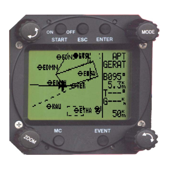
LX5000 March 2002 3.2.3 APT Airports This is one of the three main navigation modes (APT, TP, TSK). To change the mode simply rotate themode selector. The first page shows the basic navigation data (bearing, distance, ground track and ground speed). Additional information will follow in four more nav.-pages activated using the UP/DOWN selector. -
Page 27: Airport Selection, Team Function And Wind Calculation
LX5000 March 2002 The glider symbol is all the time in the middle of the screen and the map is moving. To change the ZOOM simply rotate the ZOOM knob left or right. Following nav. page can be disabled in setup under. PAGE 3. Desired track Ground speed Off course dist. - Page 28 LX5000 March 2002 In case of a mistake use START button (or ZOOM) to step back. If the ICAO-Code is unknown, the indirect way should be used. Simply confirm ICAO with ESC and select the state in which the airport is located (UP/DOWN selector). After the state is selected, four stars are to be replaced with first four letters of the airport.
-
Page 29: Tp (Turnpoints)
LX5000 March 2002 Wind calculation method Manual corrections Wind in direction and speed GSPEED DIF. is the simplest method. The calculation based on ground speed changes affected by wind influence during a circle. To get the first result a minimum of two full circles is necessary. The message WAIT2 or WAIT 1will inform the pilot how many circles should be done to get the result. -
Page 30: Tp Edit
LX5000 March 2002 3.2.4.2 TP EDIT Using this function the pilot is able to change TP data any time. The turnpoints in LX5000 have four attributes. Using attributes, the turnpoints will appear in the graphic´s, screen marked with special symbols. The four different types of turnpoints are as follows: •... -
Page 31: Team
LX5000 March 2002 3.2.4.5 TEAM The same as described in APT. 3.2.4.6 WIND The same as described in APT. 3.2.4.7 TP QUICK (memorizing of actual position) The procedure can be activated by pressing START key on the TP-mainpage only ! The names of such points are offered in two different forms. -
Page 32: Tsk Select
LX5000 March 2002 Approaching to the TP, NEAR message will inform the pilot that he is closing on the turnpoint. After the INSIDE message is displayed, the pilot is definitively sure that he has reached the observation zone (for inst. photosector). The tasks are numerated from 00 to 99 and the turnpoints building a task from 0 up to 9. - Page 33 LX5000 March 2002 Please note: these settings are so called local settings. That means: If one enters again the menu SETUP / OBS.ZONE (under password, which are the “global” sectors for all tasks) after having set individual task sectors, all the local (individual) settings will be deleted and set back to the global values! At the turnpoint sector setting one will find an additional setup item: AUTO NEXT.
-
Page 34: Task New
LX5000 March 2002 Arrival time at the turnpoint flight time to the turnpoint remaining distance needed averaged speed to the task goal remaning AAT-time Using ESC one gets for 3 sec. ETA and ETE calculated up to the task goal. The needed averaged speed is calculated from the remaining distance and the remaining AAT-time. -
Page 35: Statistics
LX5000 March 2002 3.2.6 Statistics This mode is exclusively used to give the pilot information about his actual flight. There are two levels of statistics during the flight. Flight statistics is always active; the task statistics will be active after a task is started. On the ground only the logbook is available. -
Page 36: Log Book
LX5000 March 2002 3.2.6.3 LOG BOOK This kind of statistics is available only on ground. The logbook shows the flights under date, take off and landing. The logbook will appear appr. 3 minutes after landing and this is the sign that the flight is finished. 3.2.6.4 Statistics after flight The LX5000 offers flight statistics and flight analyses. - Page 37 LX5000 March 2002 The zoom procedure is similar, but there is no cross. After enter a vertical bar will appear which can be moved (UP/DOWN) and fixed with enter again. The same way is used for the second bar. Statistics: After pushing ENTER a task recalculation will follow.
-
Page 38: Variometer
LX5000 March 2002 3.3 Variometer All analogue signals of LX5000 (altitude, speed) are derived from high quality pressure sensors which means no flask is necessary. The vario signal is derived from the altitude signal. All signals are temperature compensated. Vario and speed signals are altitude compensated as well. -
Page 39: Speed Command
LX5000 March 2002 3.3.3 Speed command Speed command is a very useful help to optimize the speed. There are many visual indicators (see LCD Vario). After the instrument changes to speed command mode, the audio will change and inform the pilot about his speed. Not to mix vario audio and speed command audio some special features were developed: •... -
Page 40: Set Alt (Take Off Elevation Input)
LX5000 March 2002 If the password was repeated correctly (having less than 4 chracters, one can skip the remaining „stars“ with ENTER or ESC), the last settings, used by that pilot will be restored. If the pilot is using no password, the last flown settings are restored, but there is no guarantee, that other pilots have not used his settings and changed something. -
Page 41: Preparing A Task
LX5000 March 2002 If a task (TSK) is to be flown successfully, please take care of some important things: • Choose the correct task. You should prove (using the EDIT-mode) the correctness and the sequence of the single points. • Point „0“... -
Page 42: Starting A Task
LX5000 March 2002 3.4.4.2 Starting a task If the glider is flying into the start sector and the pilot decides to start the task, the following steps must be followed to start the task:: • Wait unti the message INSIDE appears •... -
Page 43: Tsk End
LX5000 March 2002 3.4.4.5 TSK END After reaching the finish zone the task stops automatically. A very typical message TSK END will appear. It is posssible to start a new task (during the flight) after TSK END, using the RESTART procedure. 3.4.4.6 Procedure after landing FAI regulations require a straight line by barogram at the beginning and at the end. -
Page 44: Pc And Logger Communication
Lxe and to transfer them into LX5000. Use menu ZONES in Lxe. Lxe can also be used for data base update. The data base is freely available from the LX Navigation websites The CONNECT status is realized as follows •... -
Page 45: Communication Lx5000 - Lx 20, Colibri
LX5000 March 2002 4.2 Communication LX5000 – LX 20, Colibri LX5000 is able to exchange data (bi-directional) with LX 20, Colibri and Posigraph. The following data can be transferred: • DA.4 files (TP and TSK) • Flight info To establish data transfer use following steps: STEP LX 20 LX5000... -
Page 46: Installation
LX5000 March 2002 5 Installation The LX5000 main unit needs one standrad 80-mm cut-out. Each Vario indicator needs one standrd 57 mm cut-out. Three pressure connectors are on the rear side of the instrument. A label on the rear side shows their functions. •... - Page 47 LX5000 March 2002 Dimensions for mounting: °80.0mmh11 °89.0mm page 46...
-
Page 48: Wiring
LX5000 March 2002 5.1 Wiring LX 5000 V8.x Wiring LX 5000/LX 20/COLIBRI CABLE 50 cm LX 5000 LX 20 POWER +12 V Black 50 cm SECOND SOURCE +12 V Black Shield 20 cm RS485 SUBD 9 Female SUBD 9 Female Yellow A Red +12 V White +12 V... -
Page 49: Tree Structure Diagram
LX5000 March 2002 5.2 Tree structure Diagram ⇔ MODE page 48... -
Page 50: Passwords
LX5000 March 2002 6 Passwords 96990 System parameters 55556 External NMEA input (internal GPS is disconnected) The function is active till switching OFF or new input of 5556 After using password 5556 is INTEGRITY lost 99999 Delete logger (all logger data will be deleted) Seite 49... -
Page 51: Options
LX5000 March 2002 7 Options 7.1 LX5000 Compass Module 7.1.1 General The compass module is an electronic compass (magnetic field sensor) , which was devloped for the LX5000. The LX5000 recognizes the compass module automatically, therefore only the compensation procedure and no additional settings in the LX5000 are needed. -
Page 52: Installation Of The Compass Module
LX5000 is done directly by a 9-pin SUB D connector with 3m of cable. The optimal connection is a free RS485 ports on the back side of a LCD vario indicator, where two of these ports are located. If there are no more free RS485 ports, a splitting unit can be ordered from LX Navigation. 7.1.2.1... -
Page 53: Final Test
LX5000 March 2002 1. Orientate the aircraft again to 360 2. Set the cursor on N and press ENTER (actual HDG is displayed). 3. Press ENTER again (storing the measured value) 4. Set the cursor on 45°, orientate the aircraft to 45° and again store the measured value. 5. -
Page 54: Lx5000 -Remote Control Unit
LX5000 March 2002 7.2 LX5000 –Remote control units 7.2.1 Remote control keyboard type 7.2.1.1 General The unit consists of an aluminium housing (80x60x20 mm), a rubber keyboard and a micro controller. The keys made of rubber are used to ensure comfortable manipulation. All LX5000, having a program version 8.2 or higher, are ready to support the LX-Remote. -
Page 55: Electonical Connection
LX5000 March 2002 7.2.1.3 Electonic connection As described, the LX Remote should be connected to the LX5000 RS485-BUS. To do that, a free port on the digital vario rear side (9 P female) should be used. If there are no free ports (other devices connected) it is necessary to order a RS485 Splitting Unit to split one input into 3 outputs. - Page 56 LX5000 March 2002 Seite 55...
-
Page 57: Revision History
LX5000 March 2002 7.2.2.4 Installation Generally the unit must be connected to the RS485-bus. See following examples. 8 Revision history Version 8.2 3.1.1.1 3.2.4.2 Options insert pp 49 - 53 Version 9.0 2.2.7; 3.1.1.2; 3.1.1.3; 3.1.2.5; 3.1.2.6; 3.1.2.13; 3.1.2.17; 3.2.2.1; 3.2.2.2.3; 3.2.4; 3.3.4;...
Need help?
Do you have a question about the LX5000 V9.0 and is the answer not in the manual?
Questions and answers