Table of Contents
Advertisement
Quick Links
Advertisement
Table of Contents

Related Manuals for ICP DAS USA PMC series


Summary of Contents for ICP DAS USA PMC series
- Page 1 ICP DAS PMC/PMD (Power Meter Concentrator) Series User Manual [Version 3.1.8]...
- Page 2 ICP DAS PMC/PMD Series User Manual Warning ICP DAS Inc., LTD. assumes no liability for damages consequent to the use of this product. ICP DAS Inc., LTD. reserves the right to change this manual at any time without notice. The information furnished by ICP DAS Inc. is believed to be accurate and reliable.
-
Page 3: Table Of Contents
ICP DAS PMC/PMD Series User Manual Table of Contents System Introduction ..................1 Before Installation ..................5 System Login ....................6 System Main Page ..................7 System function area ................. 8 Rules management toolbar ............8 4.1.1 Real-time information area............ 11 4.1.2 System function toolbar ............ - Page 4 ICP DAS PMC/PMD Series User Manual Polling Time Information ..............46 5.12 5.13 Modbus Table Information .............. 46 UID Information ................47 5.14 System Setting ..................49 Time Setting .................. 50 Network Setting ................52 VPN Setting (This function is for PMC-5151 only.) ......56 SNMP Setting ................
- Page 5 ICP DAS PMC/PMD Series User Manual M-7000/DL Module Setting ..........103 7.3.5 7.3.6 Modbus RTU Module Setting ..........108 Modbus TCP Module Setting ..........120 7.3.7 Logger Setting ..................122 Data Logger Setting ..............123 Event Logger Setting ..............126 FTP Upload Setting ..............
- Page 6 ICP DAS PMC/PMD Series User Manual MQTT ................196 11.1.6 11.1.7 Connection Status .............. 198 Timer ................198 11.1.8 Schedule ................199 11.1.9 11.1.10 Mobile Network Signal Strength .......... 199 FTP Upload Status ............. 200 11.1.11 11.1.12 SD Card Status ..............201 11.1.13 Rule Status ................
- Page 7 ICP DAS PMC/PMD Series User Manual List of Figures PMC/PMD System Architecture ............. 2 Figure1-1 : PMC/PMD Login page ..............6 Figure3-1 : PMC/PMD Main Page ..............7 Figure4-1 : Figure4-2 : System Function Area (login as a Administrator) ......8 System Function Area(login as a General user) ........
- Page 8 ICP DAS PMC/PMD Series User Manual Figure5-18 : Historical Data Chart for power data ..........28 Figure5-19 : Historical Data Table for power data ..........29 Figure5-20 : Historical Data Report inquiry ............29 Figure5-21 : Daily Report for PM-3133 ............31 Figure5-22 : Daily Report for PM-3114 ............
- Page 9 ICP DAS PMC/PMD Series User Manual Figure6-10 : Setting interface of VPN function ..........58 Figure6-11 : Security setting interface of VPN function ........59 Figure6-12 : SNMP Setting Page ..............60 Figure6-13 : SNMP Manager List ..............61 Figure6-14 : The Address Setting for SNMP Manager ........61 Figure6-15 : The Working Model Setting for SNMP Manager ......
- Page 10 ICP DAS PMC/PMD Series User Manual Select the actual Power Meter connected to PMC/PMD ....81 Figure7-7 : Figure7-8 : Set up the No and Address of the power meter ....... 82 Select Modbus RTU Power Meter model ........82 Figure7-9 : Figure7-10 : Add the Modbus RTU Power Meter manually ........
- Page 11 ICP DAS PMC/PMD Series User Manual Figure7-45 : Discrete Input Setting Page ............112 Figure7-46 : Discrete Input Setting Example for Modbus RTU Module ..... 113 Figure7-47 : Input Register Setting Page ............114 Figure7-48 : Input Register Setting Example for Modbus RTU Module ..... 116 Figure7-49 : Holding Register Setting Page ............
- Page 12 ICP DAS PMC/PMD Series User Manual Figure10-15 : Example of “Channel Data” Type Variable Binding List ....165 Figure10-16 : “User-Defined Data” Type Setting Page ........165 Figure10-17 : “User-Defined Data” Interface in Edit Mode ........ 166 Figure10-18 : “User-Defined Data” Interface in View Mode ......167 Figure10-19 : SNMP Trap setting with variable bindings list ......
- Page 13 ICP DAS PMC/PMD Series User Manual Figure11-15 : Broker Connection Status condition setting ........197 Figure11-16 : Subscribe Topic condition setting..........197 Figure11-17 : Connection Status condition setting page ........198 Figure11-18 : Timer condition setting page ............199 Figure11-19 : Schedule condition setting page ..........199 Figure11-20 : Mobile Network Signal Strength condition setting page ....
-
Page 14: System Introduction
ICP DAS PMC/PMD Series User Manual System Introduction The PMC(Power Meter Concentrator)/PMD(Power Meter Concentrator with Display) is an intelligent Power Meter Concentrator developed by ICP DAS. It features various functions such as: power data management, logic control, data logger and alarm notification functions. -
Page 15: Figure1-1 : Pmc/Pmd System Architecture
ICP DAS PMC/PMD Series User Manual Figure1-1 : PMC/PMD System Architecture With the built-in Web Server, it allows connection to PMC/PMD for power meter parameters and system settings via browser and allows viewing the real time or historical power data of the power meters. In addition to power data monitoring function, the PMC/PMD also could connect to ICP DAS XW-Board, XV-Board , M-7000/DL I/O modules and standard Modbus RTU/TCP Slave modules. - Page 16 ICP DAS PMC/PMD Series User Manual with the IoT service which Microsoft Azure and IBM Bluemix provide. The flexible integration ability with the SCADA/IoT/IT system make PMC-52xx/PMD a perfect concentrator of power meter in the Energy monitoring and management application of Industry 4.0 age. When using PMC/PMD to build a power management and monitoring system, during the whole process of system development, no programming is required;...
- Page 17 ICP DAS PMC/PMD Series User Manual PMD is equipped with local side TFT LCD (with Touch Panel). It provides an easy way for viewing the power data and setting the system parameters on sites. Connection with SCADA/IT/IoT system ...
-
Page 18: Before Installation
ICP DAS PMC/PMD Series User Manual local operations". 2 Before Installation Modify PMC/PMD‘s network settings to fit current network environment settings, and the default network settings of PMC/PMD is as follow: IP:192.168.255.1 Subnet mask:255.255.0.0 Gateway address:192.168.0.1 DNS Server address:8.8.8.8 (default: Google DNS Server) Steps (1) Modify the network settings of the PC or Notebook to be the same network segment as PMC/PMD. -
Page 19: System Login
ICP DAS PMC/PMD Series User Manual 5. A single I/O interface allows connections to at most 16 devices (Power meters and I/O modules). 3 System Login When connect to PMC/PMD webpage server via Web browser (IE 8 / Firefox 3.6 / Chrome 14.0.8 version or above are recommended), in order to get a better operation experience, 1280x1024 resolution is recommended. -
Page 20: System Main Page
ICP DAS PMC/PMD Series User Manual 4 System Main Page After login into the system, PMC/PMD default home page will be displayed, and will automatically read settings of the PMC/PMD to the webpage. Figure4-1 : PMC/PMD Main Page PMC/PMD main page could be divided into 3 areas: A. -
Page 21: System Function Area
ICP DAS PMC/PMD Series User Manual System function area System function area provides immediately access to the main functions of PMC/PMD, such as: system settings, system real-time information display, rule files management, etc, shown as below: Figure4-2 : System Function Area (login as a Administrator) System function area includes the following areas: A1. -
Page 22: Figure4-5 : Rules Management Toolbar (Login As A General User)
ICP DAS PMC/PMD Series User Manual If login as a general user, the rule management toolbar will be shown as below: Figure4-5 : Rules management toolbar (login as a General user) The functions of the Rules management toolbar are as follow: ... -
Page 23: Figure4-8 : Confirm To Save Settings
ICP DAS PMC/PMD Series User Manual Figure4-8 : Confirm to save settings “Logout” button allows to log out the system, click on button and click “OK” to logout the system. Figure4-9 : Confirm to logout (The settings are saved) If the settings are not saved to the PMC/PMD before performing logout, a warming message will appear as below: Figure4-10 :... -
Page 24: Real-Time Information Area
ICP DAS PMC/PMD Series User Manual 4.1.2 Real-time information area Real-time information area allows display of current free space and approximate number of days available to save of the microSD card of the PMC/PMD and the real-time system information, shown as below: Figure4-11 : Real-time information area ... -
Page 25: Sub-Function Area
ICP DAS PMC/PMD Series User Manual Sub-function area Sub-function area will display detailed functions under the selected System function. The user could edit or review detailed function options in the Sub-function area. On the upper Sub-function area, the path of current function will be displayed to show the current function path. -
Page 26: Figure4-14 : Power Data Overview Page
ICP DAS PMC/PMD Series User Manual Figure4-14 : Power data Overview page Power data overview page display the power data of the power meters that connected to the PMC/PMD. Depend on the requirement to select the desired classification of the power data to display the desired power data. The page refreshes every 20 sec, the user could also click “Refresh”... -
Page 27: Figure4-16 : Display Power Data Of The Selected Classification
ICP DAS PMC/PMD Series User Manual Figure4-16 : Display power data of the selected classification “Connection Status” will reveal the connection status between the power meter and PMC/PMD, the graphic indicators are as follow: : Online : Offline : Connecting... -
Page 28: Main Page
ICP DAS PMC/PMD Series User Manual 5 Main Page On the Main Page, 10 information display options are as follow: Power Meter Information, Power Data Information, Realtime Chart, Historical Chart, Historical Data Report, Historical Electricity Analysis, PUE Information, I/O Information, Event Log, Polling Time Information, Modbus Table Information and UID information, shown as follow: Figure5-1 :... -
Page 29: Figure5-2 : Power Meter Information Overview
ICP DAS PMC/PMD Series User Manual Figure5-2 : Power Meter Information Overview Power Meter Attribute The Power Meter Attribute section will display different information according to different power meters and the ways they are connected to the PMC/PMD. Currently PMC/PMD supports connecting to power meter via Modbus RTU (Figure 5-3) or Modbus TCP(Figure 5-4). -
Page 30: Figure5-4 : The Attribute Of Pm-3133-Mtcp Power Meter
ICP DAS PMC/PMD Series User Manual Figure5-4 : The attribute of PM-3133-MTCP Power Meter Real Time Power Information In this section, it provides real time power data information of the selected Power Meter. For 3 phase power meter, it will display real time information of Phase A, Phase B and Phase C(Figure 5-5).For single phase power meter, it will display real time information of Loop 1, Loop2, Loop3, and Loop4(Figure 5-6). -
Page 31: Figure5-6 : Real Time Power Information Of Pm-3114
ICP DAS PMC/PMD Series User Manual Figure5-6 : Real Time Power Information of PM-3114 Figure5-7 : Real Time Power Information of PM-3112 Reset Accumulated Value of the Power Meter When login as the Administrator, it allows to click on “Reset” to reset the value of kWh, kvarh, and kVAh to be 0 if required. -
Page 32: Power Meter Statistics Information Overview
ICP DAS PMC/PMD Series User Manual 5.1.2 Power Meter Statistics Information Overview On the Power Meter Statistics Information Overview page, the Demand Information section will display the Actual Demand, Forecast Demand, Contract Capacity, Hourly Maximum Demand, Daily Maximum Demand and Monthly Maximum Demand, etc. In the Statistics Information section, the Daily/Monthly/Yearly Accumulated Electricity and Daily/Monthly/Yearly Carbon Emissions for each loop... -
Page 33: Other Information
ICP DAS PMC/PMD Series User Manual 5.1.3 Other Information In the "Other" information page, users can view or setup the PT Ratio、CT Ratio、Phase Sequence、Wiring Mode、Voltage Mode and other specific parameters of the power meter. Figure5-9 : Power Meter Other Information Page 5.1.4 I/O Information In the "I/O"... -
Page 34: Power Data Information
ICP DAS PMC/PMD Series User Manual Power Data Information Power data information can be displayed in two modes (Overview and Group Overview), user can change the viewing mode according to the requirements; more detailed information will be introduced in the following sections. -
Page 35: Group Overview
ICP DAS PMC/PMD Series User Manual Figure5-12 : Change Display List Button Figure5-13 : The Power Meter List 5.2.2 Group Overview Power Data Information group overview mode allows display of power data of pre-set group of power meters (please refer to 6.8 Power Meter Group Setting). -
Page 36: Realtime Chart
ICP DAS PMC/PMD Series User Manual Select Group Select the group from the dropdown list in the “Select Group” field. If no group is pre-set, the inquiry operation will be disabled. Select Subgroup Select the subgroup from the dropdown list in the “Select Subgroup” field. -
Page 37: Figure5-15 : Realtime Chart (Power Meter Mode)
ICP DAS PMC/PMD Series User Manual Daily Accumulated Electricity, and Actual Demand. Please refer to Figure 5-15 for an example of Realtime Chart for “Power Meter Mode”. Each time the Realtime Chart displays only one power information classification. If a different power information classification is inquired, previously displayed chart will be closed automatically. -
Page 38: Group Mode
ICP DAS PMC/PMD Series User Manual icon allows to hide the markers on the chart; click on button to show the markers on the chart. “Connection Status” will reveal the connection status of the power meter, the graphic indicators are shown as follow: : Online : Offline : Connecting... -
Page 39: Figure5-16 : Realtime Chart (Group Mode)
ICP DAS PMC/PMD Series User Manual Figure5-16 : Realtime Chart (Group Mode) There are three function icons on the upper area of the Power Meter Realtime Chart: The icon allows to pause the update of the chart, only the data within the 25 minutes will be displayed. -
Page 40: Historical Chart
ICP DAS PMC/PMD Series User Manual Historical Chart Historical Chart allows display of the value and chart of power data in historical trend. Select the power meter from the dropdown list of the Power Meter List, choose the classification from the dropdown list of the Data Classification and then specify the date from the dropdown list of the Date. -
Page 41: Figure5-18 : Historical Data Chart For Power Data
ICP DAS PMC/PMD Series User Manual Historical Data Chart The historical power data of specified classification will be displayed in historical chart. The user could select the range on the below region or drag and move on the chart to adjust the viewing range. Move the mouse cursor close to the marker, the value will be displayed. -
Page 42: Historical Data Report
ICP DAS PMC/PMD Series User Manual Figure5-19 : Historical Data Table for power data On the lower left of the Historical Data Table, there are 5 function icons. Go to the first page. Go to previous page. Go to specific page. - Page 43 ICP DAS PMC/PMD Series User Manual Groups will be listed on the dropdown list of the Power Meter List. When a single power meter is selected, a power data report of the specified power meter will be generated. If a power meter group is selected, a report of the "Total accumulative electricity"...
-
Page 44: Figure5-21 : Daily Report For Pm-3133
ICP DAS PMC/PMD Series User Manual Figure5-21 : Daily Report for PM-3133 Figure5-22 : Daily Report for PM-3114 Figure5-23 : "Total Accu. Electricity" report for Power Meters Group... -
Page 45: Historical Electricity Analysis
ICP DAS PMC/PMD Series User Manual Historical Electricity Analysis Historical Electricity Analysis can be done in 3 ways: Energy Usage Analysis by Trend, Energy Usage Analysis by Time and Energy Usage Breakdown by Circuit/Group. The user can query electricity analysis for specific date by selecting Chart Type, Data Classification, Date and Loop(s)/Phase(s);... -
Page 46: Figure5-25 : Inquiry By Group Mode
ICP DAS PMC/PMD Series User Manual for inquiring: group mode and user-defined mode. Group: In group mode, the user can select group and subgroup to inquire the energy usage analysis of loops/phases of the power meters in the format of trend chart. If no group is pre-set, the user will not be able to perform inquiry operation. -
Page 47: Energy Usage Analysis By Time Period
ICP DAS PMC/PMD Series User Manual classification will be displayed in historical chart. The user could select the range on the below region or drag and move on the chart to adjust the viewing range. Move the mouse cursor close to the marker, the value will be displayed. -
Page 48: Figure5-28 : Energy Usage Analysis By Time Period
ICP DAS PMC/PMD Series User Manual energy usage comparison for each year. Figure5-28 : Energy Usage Analysis by Time Period Function Type: The user can select one of the following three options for energy analysis: Energy Usage Analysis by Trend, Energy Usage Analysis by Time Period and Energy Usage Breakdown by Circuit/Group. -
Page 49: Energy Usage Breakdown By Circuit/Group
ICP DAS PMC/PMD Series User Manual Figure5-29 : Time Histogram Chart for PM-3114 Loop 1 5.6.3 Energy Usage Breakdown by Circuit/Group The users could specify the data classification and the time range under this section, and then select the loop(s)/phase(s) to be inquired; the corresponding Energy Usage Breakdown by Circuit/Group will be displayed in category pie chart to show the Energy Usage Proportion of the loops/phases. -
Page 50: Figure5-31 : Inquiry By Group Mode
ICP DAS PMC/PMD Series User Manual for energy analysis: Energy Usage Analysis by Trend, Energy Usage Analysis by Time Period and Energy Usage Breakdown by Circuit/Group. Data Classification: includes V (voltage), I (current), PF (power factor), Energy Usage (KWh), and Maximum Demand. ... -
Page 51: Figure5-32 : Energy Usage Breakdown By Circuit/Group Chart
ICP DAS PMC/PMD Series User Manual Figure5-32 : Energy Usage Breakdown by Circuit/Group Chart... -
Page 52: Pue Information
ICP DAS PMC/PMD Series User Manual PUE Information Power Usage Effectiveness(PUE) information can be displayed in two modes(Real-Time and History), users can change the viewing mode according to the requirement;more detailed information is as below: 5.7.1 Real-Time "Real-Time" overview mode allows display of the multiple PUE values which are calculated by "Total Facility Energy"... -
Page 53: Figure5-34 : Pue Information - History(1)
ICP DAS PMC/PMD Series User Manual Figure5-34 : PUE information - History(1) PUE List:All PUE options which are preset by users will be listed on the dropdown list of the PUE List, if no PUE option is preset, the inquiry operation will not be able to perform. ... -
Page 54: I/O Information
ICP DAS PMC/PMD Series User Manual I/O Information The I/O Information page will display the real-time values of the Internal Registers of the PMC/PMD and the real-time I/O channels values of all I/O modules (including XW Board, M-7000 or DL Modules, Modbus RTU Modules and Modbus TCP modules) that are connected to the PMC/PMD. -
Page 55: I/O Realtime Chart
ICP DAS PMC/PMD Series User Manual I/O Realtime Chart I/O Realtime Chart allows display of real-time channel data of the I/O module in trend style. Select the I/O module from the dropdown list of the "I/O module List", the classification from the dropdown list of the "Type" field, the I/O channel from the "Channel Selector"... -
Page 56: I/O Historical Chart
ICP DAS PMC/PMD Series User Manual 5.10 I/O Historical Chart I/O Historical Chart allows display of I/O channel historical data of the Data Logger in trend style. Specify the date from the dropdown list of the "Date" field, select the I/O channel from the "Channel Selector" field, then click on “Inquiry”... -
Page 57: Figure5-41 : I/O Historical Data Chart
ICP DAS PMC/PMD Series User Manual Date The dates that are available for channel data retrieval will be displayed. Please note, if no log file is available, the inquiry operation will not be performed. Channel Selector All Channel of the User-Defined Data Logger will be list on the dropdown list of the "Channel Selector"... -
Page 58: Event Log
ICP DAS PMC/PMD Series User Manual 5.11 Event Log The Event Log page allows to view the list of system event logger information when login as the Administrator. Figure5-42 : Event Log information display The Event Log record including the following information: ... -
Page 59: Polling Time Information
ICP DAS PMC/PMD Series User Manual 5.12 Polling Time Information Users can check the polling time of each modules and power meters which are connected with PMC/PMD currently. The "Polling Time Information Page" is as below: Figure5-43 : Polling Time Information The graphic indicator on the right side of the No. -
Page 60: Uid Information
ICP DAS PMC/PMD Series User Manual Module Type “Module Type” includes 4 options : Power Meter, I/O Module, XW-Board, XV-Board and Other Information Module Name According to the selected “Module Type” option, the corresponding module name or information of “Module Name” will be listed. Click on “Inquiry”... -
Page 61: Figure5-46 : Power Meter Uid Information Page
ICP DAS PMC/PMD Series User Manual Figure5-46 : Power Meter UID Information Page Users can click "Export" button to export the UID information as CSV file. -
Page 62: System Setting
ICP DAS PMC/PMD Series User Manual 6 System Setting System Setting includes 6 options: Time Setting, Network Setting, SNMP Setting, Security Setting, I/O Interface Setting, Power Meter Group Setting and Other Setting. When you get into the System Setting page, the system settings information of this PMC/PMD will be displayed, as shown below: Figure6-1 : System Setting Overview Page... -
Page 63: Time Setting
ICP DAS PMC/PMD Series User Manual update on this page. For firmware update operations, please refer to 6.9 Firmware Update. Time Setting On the Time Setting page, it allows to set the time of PMC/PMD and Time Synchronization function. The setting interface is as below: Figure6-2 : Time Setting Page When get into this page, the system will read and display current time of the... -
Page 64: Figure6-3 : Time Synchronization Setting
ICP DAS PMC/PMD Series User Manual Figure6-3 : Time Synchronization Setting Follow the steps below to set up Time Synchronization Setting: i. In the “Function Status” field, check “Enable” to enable the Time Synchronization function. ii. In the “SNTP Time Server” field, input the IP address or domain name of the SNTP Time Server. -
Page 65: Network Setting
ICP DAS PMC/PMD Series User Manual Network Setting Network Setting allows making a change to network configuration, web server port or Modbus settings on the PMC/PMD. The following figure illustrates the configuration interface. Please Note:PMC-52xx/PMD series only support LAN1 setting. Figure6-4 : PMC-52xx/PMD Network Setting Page... -
Page 66: Figure6-5 : Pmc-5151 Network Setting Page
ICP DAS PMC/PMD Series User Manual Figure6-5 : PMC-5151 Network Setting Page Each time when the user enters this page, it will read and display current network configuration and port settings from the PMC/PMD. In the “Connection mode” field, please select the connection mode as “Obtain an IP address automatically (DHCP)”... -
Page 67: Figure6-6 : Signal Strength Level And Ip Address For Mobile Network
ICP DAS PMC/PMD Series User Manual “Port Setting” section, the user can modify the Web Server Port/ Modbus TCP Port/ Modbus NetID. After all settings are completed, click “Save” button to save the changes. The Network Setting (Mobile Network) section is for user to complete the setting 4G/3G Mobile... -
Page 68: Figure6-7 : Ddns Setting Page
ICP DAS PMC/PMD Series User Manual Figure6-7 : DDNS Setting Page Follow the steps below to set up Dynamic DNS service: Click the services tabs on the right-top corner of “Dynamic DNS service”. System provides two items for selection as “Service 1” and “Service 2”. -
Page 69: Vpn Setting (This Function Is For Pmc-5151 Only.)
ICP DAS PMC/PMD Series User Manual Figure6-8 : IoTstar connection setting page Please note: 1. PMC/PMD adopts Google DNS server as system default DNS server, the default IP is “8.8.8.8”, the IP can be modified to other DNS server IP if required. -
Page 70: Figure6-9 : Setting Interface Of Vpn Function
ICP DAS PMC/PMD Series User Manual Figure6-9 : Setting interface of VPN function When setting up the parameters of the VPN connection, please setup correct and suitable settings of the VPN server, TCP/IP and security according to the parameters of the remote VPN server. Please click "Test" or "Save" button to test or save the settings. -
Page 71: Figure6-10 : Setting Interface Of Vpn Function
ICP DAS PMC/PMD Series User Manual Figure6-10 : Setting interface of VPN function Please note: 1. When using VPN IP address to login the system, the below functions will be disabled: The network settings of LAN1 and LAN2 If the user wants to modify the settings of LAN1 or LAN2, please use the IP address of LAN1 or LAN2 to login the system. -
Page 72: Figure6-11 : Security Setting Interface Of Vpn Function
ICP DAS PMC/PMD Series User Manual Figure6-11 : Security setting interface of VPN function... -
Page 73: Snmp Setting
ICP DAS PMC/PMD Series User Manual SNMP Setting The PMC/PMD provides SNMP(Simple Network Management Protocol) V1 and V2c to work with the SNMP Network Management software for monitoring the system data, power meter data and I/O module data. The SNMP Setting page allows you to enable or modify the settings of the SNMP function on the PMC/PMD. -
Page 74: Figure6-13 : Snmp Manager List
ICP DAS PMC/PMD Series User Manual vi. In the “Location” field, input the “Location” string, The SNMP Manager List is a list for all SNMP Managers which will interact with the SNMP Agent of PMC/PMD. Please follow the steps as below to perform the setting for SNMP Managers. -
Page 75: Figure6-16 : Save The Snmp Manager Setting
ICP DAS PMC/PMD Series User Manual Please Note: If no "Read/Write" field on the list is enabled to accept the Read/Write commands, indicating that it will allow accepting the Read/Write commands from ANY SNMP Manager. iii. After completing the IP address and working model setting, please click button to add the SNMP Manager to the list. -
Page 76: Security Setting
ICP DAS PMC/PMD Series User Manual Security Setting Security Setting allows user to change the password that is required when access to PMC/PMD. The user could also modify the settings of FTP Server and Idle Time. The Security Setting page is as follow: Figure6-17 : Security Setting Page ... -
Page 77: Figure6-18 : Password Setting Page
ICP DAS PMC/PMD Series User Manual the passwords (administrator and guest) to this email address, for more detailed information, please refer to Appendix Figure6-18 : Password Setting Page Local FTP Server Setting In this section, it allows to enable or disable the FTP Server function on the PMC/PMD side. -
Page 78: I/O Interface Setting
ICP DAS PMC/PMD Series User Manual Idle Time Setting After the administrator login into the PMC/PMD page, when the idle time exceeds the pre-set time interval (default is 10 minutes), the administrator will be automatically logout. The idle time could be set as Disable/10/20/30/60 minutes, after the setting is completed, click “Save”... -
Page 79: Figure6-22 : Function Setting To Connect To Hmi Or Scada
ICP DAS PMC/PMD Series User Manual RTU Slave for connections to HMI or SCADA. COM3/COM4 :Reserved for Modbus RTU (RS-485) Master to connect Modbus RTU slave devices or for Modbus RTU Slave to connect HMI or SCADA. LAN:LAN connection is by default set for Modbus TCP Slave to connect HMI or SCADA. -
Page 80: Figure6-23 : Function Setting To Connect To Modbus Rtu Slave Device
ICP DAS PMC/PMD Series User Manual The settings steps are as below: i. In the “Baudrate” field, select the Baudrate from the dropdown list, the Baudrate of PMC/PMD and HMI or SCADA have to be set the same. ii. In the “Parity” and “Stop bits” fields, set up the Parity and Stop bits. The Parity and Stop bits of PMC/PMD and HMI or SCADA have to be set the same. -
Page 81: Other Setting
ICP DAS PMC/PMD Series User Manual the PMC/PMD has enough time to process the Modbus command, or shorten this value to improve the efficiency of the poll mechanism between Modbus RTU Slave device and PMC/PMD. iv. After all settings are completed, click “Save” button to save the changes. -
Page 82: Power Meter Group Setting
ICP DAS PMC/PMD Series User Manual In this section, it allows to enable and set Contract Capacity. To enable the Contract Capacity function, click on “Enable” and input the Contract Capacity. Click “Save” button to save the settings. The Contract Capacity being set will be displayed on the System Setting main page. -
Page 83: Group And Subgroup Setting
ICP DAS PMC/PMD Series User Manual Figure6-27 : Group and Subgroup Viewing 6.8.2 Group and Subgroup Setting i Click the “Set up” button ( ) of group or subgroup to open the setting window. Figure6-28 : Group Setting Figure6-29 : Subgroup Setting ii Input the group/subgroup name and click to add this... -
Page 84: Group And Subgroup Configuration
ICP DAS PMC/PMD Series User Manual group/subgroup to the lists. Click “Close” button to return to group setting page. Figure6-30 : Subgroup Setting Window 6.8.3 Group and Subgroup configuration Figure6-31 : Configurations for Subgroup group/subgroup configurations done Group/Subgroup Setting page. Please select the group/subgroup first and click on the function button to perform the configurations: ... -
Page 85: Setup The Loops/Phases Of The Subgroup
ICP DAS PMC/PMD Series User Manual and click on “Move Down” to move the group to lower order (lower index number (No.)). Copy:To copy the settings of a pre-set group to the new group, please click the radio button in front of the pre-set group and then click on “Copy”, a new group (in sequence) will be added to the list and the settings of the old group will be copied to this newly added group. -
Page 86: Loop/Phase Of Group Configuration
ICP DAS PMC/PMD Series User Manual Figure6-33 : Choose Loops/Phased of Subgroup Figure6-34 : Add Loops/Phases for Subgroup 6.8.5 Loop/Phase of group configuration Figure6-35 : Configurations for Loops/Phased of Subgroup... - Page 87 ICP DAS PMC/PMD Series User Manual The loop/phase of subgroup configurations can be done on the Power Meter Loop Setting page.. Please select the loop/phase first and click on the function button to perform the configurations: Move Up:Click the radio button in front of the loop/phase name and click on “Move Up”...
-
Page 88: Firmware Update
ICP DAS PMC/PMD Series User Manual Firmware Update PMC/PMD allows to update firmware via browser, after the update is completed; the PMC/PMD doesn’t require to reboot. Please follow the steps below: i. Please contact ICP DAS service to obtain the latest version of the PMC/PMD firmware file. -
Page 89: Figure6-37 : Firmware Update(2)
ICP DAS PMC/PMD Series User Manual iii. Browse through to select the new firmware file and click “Open”. Figure6-37 : Firmware Update(2) iv. Click “Update” to update the firmware. Figure6-38 : Firmware Update(3) v. Click “OK” to start the firmware update, to cancel the firmware update, click “Cancel”. -
Page 90: Figure6-40 : Firmware Update(5)
ICP DAS PMC/PMD Series User Manual vi. Updating the firmware Please note: when the firmware update process is started, please DO NOT close the update window or perform any system modification, or may result in unexpected failures. Figure6-40 : Firmware Update(5) vii. -
Page 91: Power Meter & I/O Module Setting
ICP DAS PMC/PMD Series User Manual 7 Power Meter & I/O Module Setting Meter / Module Setting page allows to perform settings of the power meters and I/O Modules that are connected to the PMC/PMD. After getting into the setting page, the overview page will display current setting of the power meters and I/O Modules that are connected to the PMC/PMD, shown as below: Figure7-1 :... -
Page 92: Power Meter Setting
ICP DAS PMC/PMD Series User Manual Power Meter Setting On the “Power Meter Setting” page, it allows to set up the settings of the Modbus RTU and Modbus TCP power meters that are connected to the PMC/PMD. The Power Meter Setting page is shown as below(Using PMC-5151 as an example): Figure7-2 : Power Meter Setting Page... -
Page 93: Scan To Add Modbus Rtu Power Meters
ICP DAS PMC/PMD Series User Manual 7.1.1 Scan to add Modbus RTU Power Meters Perform “Scan” to automatically build a list of Modbus RTU power meters that are connected to the PMC/PMD. The steps are as below: i Before performing the scan of the power meters, please make sure the RS-485 wirings connecting to the PMC/PMD and the power meters function well, and make sure the settings of the addresses of the power meters are completed. -
Page 94: Add Modbus Rtu Power Meter Manually
ICP DAS PMC/PMD Series User Manual Figure7-5 : Scanning the Power Meters v After the Scan operation is completed, a Power Meter List will appear (Figure 7-6). If the newly scanted module doesn’t match the module previously set on the same address, a window will appear (Figure 7-7), please select the actual device that are connected to PMC/PMD. -
Page 95: Figure7-8 : Set Up The No And Address Of The Power Meter
ICP DAS PMC/PMD Series User Manual i No: The number will be the order that the power data of the Modbus RTU power meter being stored in the PMC/PMD Modbus Table. The range is 1~16. ii Address: The address will be the Modbus address of this Modbus RTU power meter, please make sure the address setting is the same as the settings of the module, if the setting is not accurate, the connection for PMC/PMD to the power meter will be failed. -
Page 96: Add Modbus Tcp Power Meter Manually
ICP DAS PMC/PMD Series User Manual Figure7-10 : Add the Modbus RTU Power Meter manually 7.1.3 Add Modbus TCP Power Meter Manually PMC/PMD allows connection to Modbus TCP Power Meters via Ethernet, the user could add the Modbus TCP Power meter to the list manually;... -
Page 97: Power Meter List Interface
ICP DAS PMC/PMD Series User Manual Figure7-12 : Select Modbus TCP Power Meter model iv Nickname: For user to define a nickname for this power meter, this nickname will be displayed on the “Power meter Information” and “Rule Setting” pages. Default setting will be the model of the power meter. -
Page 98: Modbus Rtu Power Meter Setting
ICP DAS PMC/PMD Series User Manual and click on “Move Up” to move the power meter to upper order (upper index number (No)). Move Down: Click the radio button in front of the power meter and click on “Move Down” to move the power meter to lower order (lower index number (No)). - Page 99 ICP DAS PMC/PMD Series User Manual The settings are as follow: Nickname:For user to define nicknames for each power meter, this nickname will be displayed on the “Power Meter Information” and “Rule Setting” pages. Description: The Description field provides a space for the user to make a brief description of this power meter.
-
Page 100: Figure7-16 : Pm-3114 Setting Page
ICP DAS PMC/PMD Series User Manual The Single-Phase Modbus RTU Power Meter Setting page is shown as follow (using PM-3114 as an example): Figure7-16 : PM-3114 Setting Page The settings are as follow: For the settings of Nickname, Description, Address, Scan Rate, Polling Timeout, Retry Interval and Main Power Meter, please refer to “Three-Phase Modbus RTU Power Meter Setting”... -
Page 101: Modbus Tcp Power Meter Setting
ICP DAS PMC/PMD Series User Manual After all settings are completed, click “OK” button to return to the Power Meter List. 7.1.6 Modbus TCP Power Meter Setting PMC/PMD support ICP DAS Single-phase Modbus TCP Power Meters, the following section will give more detailed settings of the power meter setting page. - Page 102 ICP DAS PMC/PMD Series User Manual the module, if the setting is not accurate, the connection for PMC/PMD to the power meter will be failed. NetID: The setting will be the NetID of this power meter, please make sure the NetID is the same as the settings of the module, if the setting is not accurate, the connection for PMC/PMD to the power meter will be failed.
-
Page 103: Xw-Board/Xv-Board Setting (Pmd Series Does Not Support This Function.)
ICP DAS PMC/PMD Series User Manual XW-Board/XV-Board Setting (PMD series does not support this function.) XW-Board is used to connect with PMC-5151. XV-Board is used to connect with PMC-52xx. The setting page allows the user to set up the XW-Board/XV-Board that are connected to the PMC-5151/PMC-52xx. The XW-Board/XV-Board Setting page is shown as follow (using XW-Board as an example): Please note: Each PMC-5151 is allowed to connect to one XW-Board... -
Page 104: Xw-Board/Xv-Board Do Channel Settings
ICP DAS PMC/PMD Series User Manual Figure7-19 : XW-Board DI attribute setting page The settings are as follow: Nickname:For user to define nicknames for each I/O channel, this nickname will be displayed on the “I/O Information” and “Rule Setting” pages. ... -
Page 105: Figure7-20 : Xw-Board Do Attribute Setting Page
ICP DAS PMC/PMD Series User Manual Figure7-20 : XW-Board DO attribute setting page The settings are as follow: Nickname:For user to define nicknames for each I/O channel, this nickname will be displayed on the “I/O Information” and “Rule Setting” pages. ... -
Page 106: Xw-Board/Xv-Board Ai Channel Settings
ICP DAS PMC/PMD Series User Manual DI Status Mapping: When “DI Status Mapping” is selected, the status of the DI channel with the same channel number on the XW-Board will be copied to the DO channel. For example, when the “DI Status Mapping” is enabled on DO0, when the DI0 status is ON, DO0 will set to be ON, and when the DI0 status is OFF, DO0 will set to be OFF as well. -
Page 107: Figure7-22 : Ai Deadband Operation(> Or >= A Numerical Value)
ICP DAS PMC/PMD Series User Manual The IF Condition will use this already-adjusted value in the evaluation operation, and the AI value retrieved from the “I/O Information” page or Modbus Table via PMC-5151 would be the adjusted value. The default value for MAX and MIN is 0, it means the Scale function is disabled. -
Page 108: Figure7-23 : Ai Deadband Operation(< Or <= A Numerical Value)
ICP DAS PMC/PMD Series User Manual AI<10mA, THEN DO=ON, ELSE DO=OFF, that means, when AI receives a signal which is lower than 10mA, the DO channel will change to ON immediately, however, when the AI channel value exceed 10mA, the DO channel will not change back to OFF immediately until the value reaches 12mA (10mA plus the Deadband value 2mA), as shown in the following figure. -
Page 109: Xw-Board/Xv-Board Ao Channel Settings
ICP DAS PMC/PMD Series User Manual After all settings of the channels are completed, click “OK” button to return to XW-Board/XV-Board Setting page. Please Note: XW-310C supports two AI type: Differential and Single-ended. When the “Differential” is selected, the number of the AI channels will be 4, and when the “Single-ended”... -
Page 110: I/O Module Setting
ICP DAS PMC/PMD Series User Manual I/O Module Setting PMC/PMD allows connections to ICP DAS M-7000/DL modules. It also supports standard Modbus RTU or Modbus TCP I/O modules. The I/O Module Setting page allows user to add Modbus RTU or Modbus TCP I/O modules that are connected to the PMC/PMD to the list. -
Page 111: Scan To Add Icp Das M-7000/Dl Modules
ICP DAS PMC/PMD Series User Manual 7.3.1 Scan to Add ICP DAS M-7000/DL Modules The user could use Scan function to add ICP DAS M-7000/DL Modules to the PMC/PMD, the steps are as below: i Click on button to scan the M-7000/DL modules that are connected to the PMC/PMD. -
Page 112: Figure7-29 : Scanning The M-7000/Dl Modules
ICP DAS PMC/PMD Series User Manual Figure7-29 : Scanning the M-7000/DL modules iv After the Scan operation is completed, an M-7000/DL module list will appear (Figure 7-30). If the newly scanted module doesn’t match the module previously set on the same address, a window will appear (Figure 7-31), please select the actual device that are connected to PMC/PMD. -
Page 113: Add Modbus Rtu Module (Or M-7000/Dl Module) Manually
ICP DAS PMC/PMD Series User Manual 7.3.2 Add Modbus RTU Module (or M-7000/DL Module) Manually In addition to perform Scan operation to automatically add M-7000/DL modules to the list, the user could also add the Modbus RTU module (or M-7000/DL module) manually one by one, the steps are as below: i No: The number will be the order that the I/O channel data of the Modbus RTU module being stored in the PMC/PMD Modbus Table. -
Page 114: Add Modbus Tcp Module Manually
ICP DAS PMC/PMD Series User Manual to the Modbus RTU module and get no response. The unit will be second. the setting range will be 3 ~ 65535 seconds. vi Click to add the Modbus RTU module to the list (Figure 7-34). After adding the Modbus RTU module, click “Save”... -
Page 115: I/O Module List Interface
ICP DAS PMC/PMD Series User Manual Figure7-36 : Add the Modbus RTU Power Meter manually 7.3.4 I/O Module List Interface After the Modbus RTU I/O module or Modbus TCP I/O module are added to the I/O Module list via auto scan or manual work, the Modbus RTU I/O modules and Modbus TCP I/O modules will be listed as below: Figure7-37 :... -
Page 116: M-7000/Dl Module Setting
ICP DAS PMC/PMD Series User Manual front of the pre-set Modbus I/O module and then click on “Copy”, a new Modbus I/O module (in sequence) will be added to the list and the settings of the old Modbus I/O module will be copied to this newly added Modbus I/O module. -
Page 117: Figure7-38 : M-7000 Di Channel Setting Page
ICP DAS PMC/PMD Series User Manual The DI channel setting for M-7000 module The M-7000 module DI channel setting interface is shown as below (using M-7052 as an example) Figure7-38 : M-7000 DI Channel Setting Page The settings are as below: ... -
Page 118: Figure7-39 : M-7000/Dl Do Channel Setting Page
ICP DAS PMC/PMD Series User Manual modules, please use DCON Utility to set the value. The DO channel setting for M-7000/DL module The M-7000/DL module DO channel setting interface is shown as below (using M-7060 as an example) Figure7-39 : M-7000/DL DO Channel Setting Page The settings are as below: ... -
Page 119: Figure7-40 : M-7000/Dl Ai Channel Setting Page
ICP DAS PMC/PMD Series User Manual After all settings are completed, click “OK” button to save the changes and return to Modbus RTU Module List. Please Note: To set up the Power On value of the DO channels on M-7000/DL modules, please use DCON Utility to set the value. -
Page 120: Figure7-41 : M-7000 Ao Channel Setting Page
ICP DAS PMC/PMD Series User Manual The settings are as below: Nickname:For user to define nickname for each I/O channel, this nickname will be displayed on the “I/O Information” and “Rule Setting” pages. Type: Select the input signal type of the AI channel from the dropdown list. -
Page 121: Modbus Rtu Module Setting
ICP DAS PMC/PMD Series User Manual Type: Select the output signal type of the AO channel from the dropdown list. After all settings are completed, click “OK” button to save the changes and return to Modbus RTU Module List. Please note: To set up the Power On value of the AO channels on M-7000 modules, please use DCON Utility to set the value. - Page 122 ICP DAS PMC/PMD Series User Manual Nickname:For user to define nickname for each I/O channel, this nickname will be displayed on the “I/O Information” and “Rule Setting” pages. Description: The Description field provides a space for the user to make a brief description of this module.
-
Page 123: Figure7-43 : Coil Output Setting Page
ICP DAS PMC/PMD Series User Manual Figure7-43 : Coil Output Setting Page The settings are as follow: Data Model: PMC/PMD offers 4 Data Model selections to match the Modbus RTU Slave module configuration. The Data Model list is as follow. In this case, please select ”Coil Output(0x)”. -
Page 124: Figure7-44 : Coil Output Setting Example For Modbus Rtu Module
ICP DAS PMC/PMD Series User Manual continuous Coil Output data in the setting. So that the PMC/PMD can access the 00050, 00051, 00052 and 00053 Coil Output address of the module, and these retrieved Coil Output data will be kept in PMC/PMD Modbus Address 00300, 00301, 00302 and 00303. -
Page 125: Figure7-45 : Discrete Input Setting Page
ICP DAS PMC/PMD Series User Manual After all Coil Output settings of the Modbus RTU module are completed, click “OK” button to save the changes. The Discrete Input Setting of Modbus RTU Module The Modbus RTU module Discrete Input Setting page is shown as follow: Figure7-45 : Discrete Input Setting Page... -
Page 126: Figure7-46 : Discrete Input Setting Example For Modbus Rtu Module
ICP DAS PMC/PMD Series User Manual continuous Discrete Input data in the setting. So that the PMC/PMD can access the 10020, 10021, 10022, 10023, 10024, and 10025 Discrete Input address of the module, and these retrieved Discrete Input data will be kept in PMC/PMD Modbus Address 10300, 10301, 10302, 10303, 10304 and 10305. -
Page 127: Figure7-47 : Input Register Setting Page
ICP DAS PMC/PMD Series User Manual After all Discrete Input settings of the Modbus RTU module are completed, click “OK” button to save the changes. The Input Register Setting of Modbus RTU Module The Modbus RTU module Input Register Setting page is shown as follow: Figure7-47 : Input Register Setting Page... - Page 128 ICP DAS PMC/PMD Series User Manual would like to retrieve from the Start Address. Type: The system support 6 kinds of data type setting for Input Register of Modbus RTU module. The 6 Data Type options are “16-bit Signed Integer”, “16-bit Unsigned Integer”, “16-bit Hex”, “32-bit Signed Long”, “32-bit Unsigned Long”, and “32-bit Floating Point”.
-
Page 129: Figure7-48 : Input Register Setting Example For Modbus Rtu Module
ICP DAS PMC/PMD Series User Manual 30304. Figure7-48 : Input Register Setting Example for Modbus RTU Module To modify the starting address or quantity setting, please click on the setting block to perform the modification. The user could also modify Type, Scale Ratio, Offset and Deadband on this interface. -
Page 130: Figure7-49 : Holding Register Setting Page
ICP DAS PMC/PMD Series User Manual If the user wants to assign a Nickname for the address blocks, the user can click on the “Nickname Setting” tab, and then input the Nickname for each address block. The Nickname will be shown in the “I/O Information”... - Page 131 ICP DAS PMC/PMD Series User Manual Register(4x) on the Modbus RTU Slave module you would like to retrieve. Data Number: After finishing the Start Address setting, specify the Data Number, it is the number of Holding Register data you would like to retrieve from the Start Address.
-
Page 132: Figure7-50 : Input Register Setting Example For Modbus Rtu Module
ICP DAS PMC/PMD Series User Manual 2 continuous Holding Register data in the setting, and the data type is “32-bit Floating Point”. So that these retrieved Holding Register data will be kept in PMC/PMD Address 40300 and 40302. Figure7-50 : Input Register Setting Example for Modbus RTU Module ... -
Page 133: Modbus Tcp Module Setting
ICP DAS PMC/PMD Series User Manual 7.3.7 Modbus TCP Module Setting PMC/PMD allows connections to modules that support Modbus TCP Slave protocol for offering I/O interface function. Through Modbus TCP protocol, it enables to read or write 4 types of Modbus data (Coil Output, Discrete Input, Input Register and Holding Register) from the Modbus TCP Slave modules. -
Page 134: Figure7-52 : Modbus Tcp Slave Module Setting Page(2)
ICP DAS PMC/PMD Series User Manual the module. If the setting is not accurate, the connection for PMC/PMD to the module will be failed. Scan Rate: Input the time interval for PMC/PMD to periodically retrieve the I/O channel data of this Modbus TCP module, the setting range will be 0 ~ 65535 seconds. -
Page 135: Logger Setting
ICP DAS PMC/PMD Series User Manual 8 Logger Setting The Logger Setting function of the PMC/PMD provides recording of the power data from power meters and the I/O channel data from I/O modules. It includes Power Data Logger and User-Defined Data Logger. The Power Data Logger is exclusive for the recording of the power data, and User-Defined Data Logger allows user to define his own data recording options from power data, I/O channel data or Internal Register data. -
Page 136: Data Logger Setting
ICP DAS PMC/PMD Series User Manual Data Logger Setting On the Data Logger Setting page, the user could enable the Power Data Logger, I/O Data Logger or User-Defined Data Logger of the PMC/PMD if required. The Power Data Logger allows recording the power data of the power meters that are connected to the PMC/PMD, the I/O Data Logger allows recording all the data of the I/O modules that are connected to the PMC/PMD, and the User-Defined Data Logger allows recording... - Page 137 ICP DAS PMC/PMD Series User Manual Follow the steps below: i Check “Enable” in the “Function Status” field under the Power Data Logger section to enable the Power Data Logger function. Set the data log mode to be “Average” or “Instantaneous” from the dropdown list of the “Log Mode”.
- Page 138 ICP DAS PMC/PMD Series User Manual Select the “Source”, “Module” and “Channel” from the dropdown list and click “Insert” to add channel value encoded string into the “Data Format” content. The system will record the data the user pre-set in the Data Format, and will save the real data values in the data log file.
-
Page 139: Event Logger Setting
ICP DAS PMC/PMD Series User Manual one-time data recording for the Power Data and User-Defined Data. viii In the “File Name Format” field, select the File Name Format of the log file from the dropdown list, YYYY indicates western year, MM indicates month, DD indicates date, and the file format is CSV. -
Page 140: Ftp Upload Setting
ICP DAS PMC/PMD Series User Manual FTP Upload Setting Both Power Data logger files and User-Defined Data logger files can be upload to remote FTP server of the manage center via FTP protocol. The FTP Upload Setting page allows to set up parameters for FTP Upload, the setting page is shown as below: Figure8-4 : FTP Upload Setting Page... -
Page 141: Cloud Upload Setting
ICP DAS PMC/PMD Series User Manual field. And then select the Frequency from the dropdown list of the “Frequency” field. The Frequency can be set as: once a day, once a week or once a month. vi After all settings are completed, click “Save” button to save the changes. -
Page 142: The Path Of Data Log File
ICP DAS PMC/PMD Series User Manual The Path of Data Log File The data logger files of PMC/PMD will all be saved in the microSD card. The following section will explain the path of the data logger files saved in the microSD card: ... - Page 143 ICP DAS PMC/PMD Series User Manual Daily Report Log \ 192.168.100.20_502_00D3 [3112]1 \ 2013-05-23Rpt.csv Monthly Report Log \ 192.168.100.20_502_00D3 [3112]1 \ 2013-05Rpt.csv 為該電表的 ID; 192.168.100.20_502_00D3[3112]1 192.168.100.20_502_00D3[3112]1 is the ID of this power meter. 192.168.100.20 indicates the connection IP of the power meter; indicates the port number of the power meter;...
-
Page 144: The Format Of The Power Data Logger File
ICP DAS PMC/PMD Series User Manual The format of the Power Data Logger file The power data logger files generated are in CSV format. Each line represents one record; each field in the line is separated by a comma. The data sequences from left to right in the line of the power data are as follows: PM-2133 / PM-3133(-MTCP) Data Logger Field Date, Time, Power meter ID,... - Page 145 ICP DAS PMC/PMD Series User Manual kVA, PF, kWh, kvarh, kVAh, Daily tot. Electricity , Current demand (kWh) ..Submeter 8 Phase A/CT22 [ Voltage, Current, kW, (15/30/60 mins) kvar, kVA, PF, kWh, kvarh, kVAh, Daily tot. Electricity , Current (kWh) demand( Phase B/CT23 [...
-
Page 146: The Format Of The Power Report File
ICP DAS PMC/PMD Series User Manual The format of the Power Report file The power report files are saved in CSV format. Each line represents one record; each field in the line is separated by a comma. The data sequences from left to right in the line of the power report are as follows. - Page 147 ICP DAS PMC/PMD Series User Manual PM-4324/PM-4324A Daily Report Date, Time, Power meter ID, Submeter 1 [Timing of hourly max kW, hourly max kW, hourly total Electricity, Average hourly PF, Average hourly current, Average hourly voltage, Average hourly kVA, Average hourly kvar], [Timing of hourly max kW, hourly max kW, hourly total Electricity, Average hourly PF, Average hourly current, Average hourly voltage,...
- Page 148 ICP DAS PMC/PMD Series User Manual PM-4324/PM-4324A Monthly Report Date, Time, Power meter ID, Submeter 1 [Timing of daily max kW, daily max kW, daily total Electricity, Average daily PF, Average daily current, Average daily voltage, Average daily kVA, Average daily kvar], [Timing of daily max kW, daily max kW, daily total Electricity, Average daily PF, Average daily current, Average daily voltage, Average...
-
Page 149: The Format Of User-Defined Data File
ICP DAS PMC/PMD Series User Manual The Format of User-Defined Data File The User-Defined Data files are saved in CSV format. Each line represents one record, after the log format of the data being set in User-Defined Data Logger, the User-Defined Data Logger will record the data according to the data format and content set by the user. -
Page 150: Iot Platform Setting
ICP DAS PMC/PMD Series User Manual 9 IoT Platform Setting The IoT Platform Setting function of the PMC-52xx/PMD allows to build a connection to Microsoft Azure or IBM Bluemix directly. It can also connect to MQTT Brokers like Amazon CloudMQTT. Based on the IoT Platform Setting function, PMC-52xx/PMD can publish the power data and I/O channel data of the power meter and I/O modules that are connected to PMC-52xx/PMD to the IoT Cloud Platform for future data analysis, and receive the command message from IoT Cloud Platform to... - Page 151 ICP DAS PMC/PMD Series User Manual Follow the steps below: i Check “Enable” in the “Function Status” field to enable the connection to Microsoft Azure IoT Cloud Platform. ii In the “SAS Token” field, input the SAS Token which you previously registered for this PMC-52xx/PMD from Microsoft Azure.
-
Page 152: Figure9-2 : Microsoft Azure Publish Message Setting Page
ICP DAS PMC/PMD Series User Manual Figure9-2 : Microsoft Azure Publish Message setting page viii Input a name in the “Nickname” field and you could also input the description of this Publish Message in the “Description” field. ix In the “Message Type” field, select the “Channel Data” to prepare a Publish Message with the power data or I/O channel value. -
Page 153: Figure9-3 : "User-Defined Data" Setting Interface Of Iot Platform
ICP DAS PMC/PMD Series User Manual “User-Defined Data” Setting Interface of IoT Platform Figure9-3 : x The timing to publish message is set in the “Auto Publish” field, there are two options: “When the I/O data changed and the variation exceeds xxx”... - Page 154 ICP DAS PMC/PMD Series User Manual example of a message the PMC-52xx/PMD receives: "Target":"door", "Action":"open", "Timestamp":"2016/10/17 15-17-22" In this example, the “Target” and “Action” variable setting will be performed first. Each time when the PMC-52xx/PMD receives the message, it will retrieve the corresponding value of the “Target” and “Action”...
-
Page 155: Ibm Bluemix Setting
ICP DAS PMC/PMD Series User Manual IBM Bluemix Setting On the IBM Bluemix Setting page, the user could enable the connection to IBM Bluemix IoT Cloud Platform if required. The setting page is shown as below: Figure9-5 : IBM Bluemix Setting page Follow the steps below: i Check “Enable”... -
Page 156: Figure9-6 : Ibm Bluemix Subscribe Message Setting Page
ICP DAS PMC/PMD Series User Manual Web page. iii The value in “keep alive Time” field defines the maximum amount of time in second that pass away without communication between the PMC-52xx/PMD and IBM Bluemix. The “keep alive interval” enables IBM Bluemix to detect if the connection to the PMC-52xx/PMD is no longer available without having to wait for the long TCP/IP timeout. -
Page 157: Mqtt Setting
ICP DAS PMC/PMD Series User Manual which is defined in the message of the Subscribe Topic. After completing the setting, click the "Add" button to add the variable. For the message the PMC-52xx/PMD receives from IBM Bluemix is based on JSON format, the PMC-52xx/PMD can also get the corresponding value of the variable from the received message. -
Page 158: Figure9-7 : Mqtt Setting Page (Broker)
ICP DAS PMC/PMD Series User Manual at the same time, and the Topic setting for the two Brokers is also independent. The configuration page of MQTT Broker setting is shown as below: Figure9-7 : MQTT Setting Page (Broker) The settings steps are as below: i. - Page 159 ICP DAS PMC/PMD Series User Manual iii. In the Broker parameters setting page, you can input the name of the Broker in the “Nickname” field and you could also input the description of this Broker in the “Description” field. iv. Check “Enable” or “Disable” in the “Initial Status” field to enable the initial connection status with the Broker.
-
Page 160: Figure9-9 : Publish Message And Subscribe Topic Setting Page
ICP DAS PMC/PMD Series User Manual “Enable” checkbox, the setting of Last Will Topic, Message content and QoS will be brought up. xiii. The value in "Periodical Publish Interval" field defines the time interval (in second) to send all Publish Topics with the “Periodical Publish”... -
Page 161: Figure9-10 : Publish Message Setting Page
ICP DAS PMC/PMD Series User Manual Figure9-10 : Publish Message Setting Page xvii. Input a name in the “Nickname” field and you could also input the description of this Publish Message in the “Description” field. xviii. In the “Message Type” field, select the “Channel Data” to prepare a Publish Message with the power data or I/O channel value. - Page 162 ICP DAS PMC/PMD Series User Manual The user can select “User-Defined Data” in “Message Type” field to edit the Publish Topic and its binding message on the free style editing interface. The user interface is shown as below. xix. In the “QoS” field, user can select 0, 1, 2 for the QoS(Quality of Service) setting for the Publish Message.
-
Page 163: Topic Import/Export Setting
ICP DAS PMC/PMD Series User Manual The Interface will be shown as below: Figure9-11 : Subscribe Topic Setting Page xxv. Input a name of the Subscribe Topic in the “Nickname” field, and you could also input the description of this Subscribe Topic in the “Description”... - Page 164 ICP DAS PMC/PMD Series User Manual Import/Export Setting page is shown as below. MQTT Topic Import/Export setting page All MQTT Publish Topics and Subscribe Topics that the PMC-52xx/PMD is using now will be shown in the setting page. Click the “Export” button will collect all topics into the “topics.csv” file. The format of the “topics.csv”...
- Page 165 ICP DAS PMC/PMD Series User Manual The Import of MQTT Topic...
-
Page 166: Advanced Setting
ICP DAS PMC/PMD Series User Manual 10 Advanced Setting Advanced Setting provides additional features and allows you to perform more setting on the PMC devices. Click on the Advanced Setting button, a column of buttons will appear on the left of the page: ... -
Page 167: Figure10-1 : Email Setting Page
ICP DAS PMC/PMD Series User Manual Figure10-1 : Email setting page The settings steps are as below: i Click on “Add new email” to add a new email setting. After clicking the “Add new email”, a setting page will appear, input name in the “Name”... -
Page 168: Figure10-3 : Email Setting Page(Smtp Server)
ICP DAS PMC/PMD Series User Manual Figure10-3 : Email setting page(SMTP Server) iv Input the Port number, the default port number is set as 25. If the SMTP server requires account and password validation, please select the “Enable” checkbox, and continue steps vi~viii to login into the SMTP server. -
Page 169: Figure10-5 : Email Setting Page(Email Content)
ICP DAS PMC/PMD Series User Manual After complete Email Address setting, continue to input Email Content setting. Enter the email subject in the “Subject” field. The Email Content Setting page is shown as below: Figure10-5 : Email setting page(Email Content) xiii Enter the content in the “Content”... -
Page 170: Sms Setting
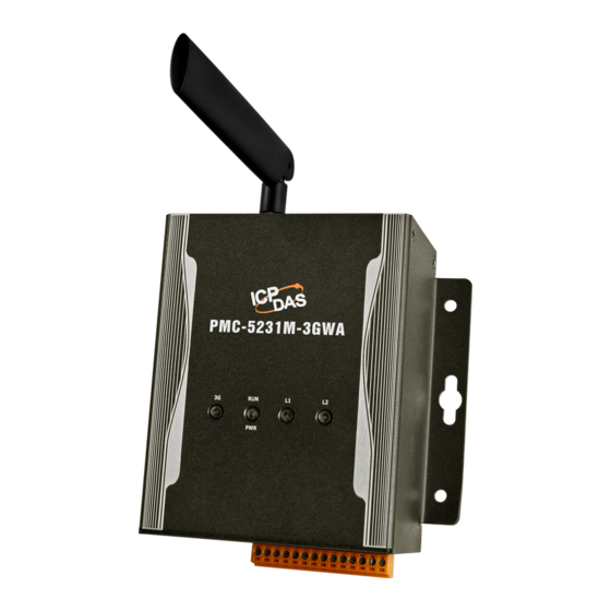
ICP DAS PMC/PMD Series User Manual 10.2 SMS Setting PMC-5231M-4GE/PMC-5231M-4GC/PMC-5231M-3GWA/PMC-5151/PM D offers SMS Alarm message sending and SMS Command receiving functions (PMC-5151/PMD required ICP DAS GTM-203M-3GWA modem. Please refer to Appendix III for detail). For SMS Alarm function; it allows to send pre-set SMS alarm message to specific phone numbers. -
Page 171: Figure10-7 : Sms Setting Page (2)
ICP DAS PMC/PMD Series User Manual iii Click “Add new SMS alarm”, the SMS Alarm Setting page will appear as follow: Figure10-7 : SMS Setting Page (2) iv Input name in the “Name” field and you could also input the description of this SMS Alarm in the “Description”... -
Page 172: Sms Command Setting
ICP DAS PMC/PMD Series User Manual viii Repeat steps iii~vii to complete settings of all SMS Alarm setting. ix To modify the settings of a pre-set SMS Alarm, please click on the radio button in front of the SMS Alarm, and then click on “Setting” to modify the settings. - Page 173 ICP DAS PMC/PMD Series User Manual disabled. iv In the “Authorized Phone Number” field, click on “Add” to input the phone numbers you would like to authorize to send SMS commands to PMC/PMD. Keep on clicking “Add” to add all phone numbers to send the SMS commands to PMC/PMD, click “Remove”...
-
Page 174: Figure10-9 : Sms Command Setting For Get Command
ICP DAS PMC/PMD Series User Manual Figure10-9 : SMS Command Setting for GET Command Figure10-10 : SMS Command Setting for SET Command vii Click on “OK” to confirm the setting and leave the setting page. viii Repeat steps v~vii to complete settings of all SMS Command setting. - Page 175 ICP DAS PMC/PMD Series User Manual On Figure 10-11, taking the first SMS Command on the list as an example, when user send SMS message “DATA” to PMC-5151, PMC-5151 will send back the data of DI0, DI1, & DI2 of the XW310C(XW-Board), the Total/Average value of the kW from module PM-2133(2) on COM2, and value of Internal Register 1 to the command sender.
-
Page 176: Snmp Trap Setting
ICP DAS PMC/PMD Series User Manual 10.3 SNMP Trap Setting SNMP Trap function allows PMC/PMD to initiative sending of the system data, power meter data and IO channel data to the SNMP Manager in real time automatically when unusual events occur; so that the SNMP Manager can respond immediately with corresponding operations. -
Page 177: Figure10-14 : "Channel Data"Type Setting Page
ICP DAS PMC/PMD Series User Manual input the description of this SNMP Trap in the “Description” field. iv Input the Specific ID value of the SNMP Trap in the “Specific ID” field. Click on “Add new variable bindings” to add a new variable binding for the SNMP Trap. -
Page 178: Figure10-15 : Example Of "Channel Data" Type Variable Binding List
ICP DAS PMC/PMD Series User Manual Figure10-15 : Example of “Channel Data” Type Variable Binding List vii You can select the “User-Defined Data” as the variable type. The setting page interface will be shown as below: Figure10-16 : “User-Defined Data” Type Setting Page Set up the content in the “User-Defined Data”... -
Page 179: Figure10-17 : "User-Defined Data" Interface In Edit Mode
ICP DAS PMC/PMD Series User Manual Figure10-17 : “User-Defined Data” Interface in Edit Mode Input your message in the “User-Defined Data” field, and then select the “Source”, “Module” and “Channel” from the dropdown list and click “Insert” to add channel value encoded string into the “User-Defined Data”... -
Page 180: Figure10-18 : "User-Defined Data" Interface In View Mode
ICP DAS PMC/PMD Series User Manual Figure10-18 : “User-Defined Data” Interface in View Mode After completing the setting, click the “OK” button to save the parameters and variable bindings setting, and return to the SNMP Trap Setting Page Figure10-19 : SNMP Trap setting with variable bindings list viii To copy the settings of a pre-set SNMP Trap to the new SNMP Trap, please click the radio button in front of the pre-set SNMP Trap and then click “Copy”, a new SNMP Trap (in sequence) will be added to the list... -
Page 181: Line Notify Setting
ICP DAS PMC/PMD Series User Manual added SNMP Trap. ix To remove a pre-set SNMP Trap, please click the radio button in front of the pre-set SNMP Trap and then click “Remove”. After you finishing all the SNMP Traps creation and setting, click “Save”... -
Page 182: Figure10-21 : Line Notify Message Setting Page (2)
ICP DAS PMC/PMD Series User Manual Figure10-21 : LINE Notify Message Setting page (2) Input name in the “Name” field and you could also input the iii. description of this LINE message in the “Description” field. Enter the message content in the “Content” field. LINE message provides an encoded string for you to add current power data, I/O channel data or Internal Register data into LINE messages. -
Page 183: Chat Room Setting
ICP DAS PMC/PMD Series User Manual In the “Chat Room” field, please specify the Chat rooms which will receive the message PMC-52xx/PMD send. PMC-52xx/PMD can send the messages to multi-chat rooms simultaneously. Users can directly click on the “Add new Chat Room”... -
Page 184: Figure10-24 : Line Notify Chat Room Setting Page (1)
ICP DAS PMC/PMD Series User Manual connected to the service. Users can add or manage chat rooms via the Chat Room setting page. The setting interface is as below: Figure10-24 : LINE Notify Chat Room Setting page (1) The settings steps are as below: Click “Add new chat room”, the LINE Notify Connection Setting page will appear as below. -
Page 185: Figure10-26 : Line Notify Chat Room Setting Page (3)
ICP DAS PMC/PMD Series User Manual Figure10-26 : LINE Notify Chat Room Setting page (3) iii. After login, select this account(one-to-one) or a group under this account which PMC will connect to. Figure10-27 : LINE Notify Chat Room Setting page (4) After the connection procedure is complete, the new chat room will appear in the list, and it can be selected in the message setting page. -
Page 186: Timer Setting
ICP DAS PMC/PMD Series User Manual After you finish all the LINE Notify Chat Room settings, click “Save” button to save the settings. Please Note: The limit of LINE Notify service to each chat room: The number of text message: 1000 per hour. ... -
Page 187: Figure10-29 : Timer Creating Page
ICP DAS PMC/PMD Series User Manual Assign Period : Input the period interval in units of seconds manually。 Internal Register:Assign the period interval as the value of selected internal register. Please note: The user must setup internal register before using internal register as timer period. -
Page 188: Schedule Setting
ICP DAS PMC/PMD Series User Manual Figure10-31 : Timer setting page(Internal Register) vii To copy the settings of a pre-set Timer to the new Timer, please click the radio button in front of the pre-set Timer and then click “Copy”, a new Timer (in sequence) will be added to the list and the settings of the old Timer will be copied to this newly added Timer. -
Page 189: Figure10-33 : Calendar Mode Of Schedule Setting
ICP DAS PMC/PMD Series User Manual After clicking the “Add new schedule”, a setting page will appear, input name in the “Name” field and you could also input the description of this schedule in the “Description” field. iii Select Mode to be “Calendar” or “Repeat”. ... -
Page 190: Figure10-34 : Repeat Mode Of Schedule Setting
ICP DAS PMC/PMD Series User Manual Time Range. (c.) On the calendars, click to toggle highlight on the dates you’d like to execute or not execute the operations for this Schedule. If the date shows a light green background, it indicates the date is “In Range”... -
Page 191: Pue Setting
ICP DAS PMC/PMD Series User Manual (b.) In the “Exception Date(s)” selection, click on “Add” to add the date(s) that is/are not going to execute the schedule. Click “Remove” to remove a pre-set Exception Date. (c.) In the “Time Range(s)” section, click “Add” to add new Time Range to execute this schedule. -
Page 192: Figure10-35 : Pue Setting Page(1)
ICP DAS PMC/PMD Series User Manual Figure10-35 : PUE Setting Page(1) The settings steps are as below: i Click on "Add new PUE" to add a new PUE option. ii After clicking the “Add new PUE”, a setting page will appear, select the number of the PUE from the dropdown list, input name in the “Name”... -
Page 193: Internal Register Setting
ICP DAS PMC/PMD Series User Manual Figure10-36 : PUE Setting Page(2) 10.8 Internal Register Setting PMC-5151 provides 48 Internal Registers; PMC-52xx/PMD provides 70 Internal Registers; they can be used to hold temporary variables and the data can be read/written on the Registers via Modbus command. The data on the registers can also be read and evaluated in IF Condition and be written after performing a THEN/ELSE Action. -
Page 194: Figure10-37 : Internal Register Setting Page(1)
ICP DAS PMC/PMD Series User Manual Figure10-37 : Internal Register setting page(1) The settings steps are as below: i Select the number of the Internal Register from the dropdown list, input “Name” and “Initial Value” and then click to add new Internal Register. - Page 195 ICP DAS PMC/PMD Series User Manual front of the pre-set internal register and then click “Remove”. After you finish all the Internal Registers selections and settings, click “Save” button to save the settings.
-
Page 196: Rules Setting
ICP DAS PMC/PMD Series User Manual 11 Rules Setting After finishing all Advanced Setting configurations, you can start to edit IF-THEN-ELSE rules. Click the “Rules Setting” button, a list of rules will be displayed on the left side of the page, and at the right side of the page will show detailed content of each rule that was previously defined. -
Page 197: Figure11-2 : Rules Setting Page
ICP DAS PMC/PMD Series User Manual Figure11-2 : Rules setting page Nickname: Input name in the “Nickname” field and you could also input the description of this Rule in the “Description” field. Status: Select “Enable” or “Disable”. If you select “Enable”, the rule will be executed after being downloaded. -
Page 198: If Condition Setting
ICP DAS PMC/PMD Series User Manual Setting: to edit a pre-set function component, click on to get in to the setting page of the function component. Copy: to copy a pre-set function component, click on to generate a new component with the same pre-set component settings. -
Page 199: Icp Das Module
ICP DAS PMC/PMD Series User Manual Output, Input Register and Holding Register) or power data on these modules will be automatically displayed on the dropdown list. To include subjects other than modules mentioned above in the IF Condition statement; they have to be pre-defined in Advanced Setting first. The setting options of the subjects that already being defined in Advanced Setting will appear on the dropdown list of IF Condition. -
Page 200: Figure11-4 : Di Counter Condition Setting Page
ICP DAS PMC/PMD Series User Manual iii Click “OK” button to confirm the settings and return to the Rule settings page. 11.1.1.2 DI Counter DI counter value from XW-Board/XV-Board/M-7000 module can be used as evaluation criteria for IF condition statement; the editing page for DI Counter Condition Setting is shown as follow (using XW-Board as an example) : Figure11-4 :... -
Page 201: Figure11-5 : Ai Condition Setting Page
ICP DAS PMC/PMD Series User Manual can be included in the IF condition statements; the editing page for AI Condition Setting is shown as below (using XW-Board as an example) : Figure11-5 : AI condition setting page Follow the steps below: Specify the module and channel from the dropdown list of the “Module &... - Page 202 ICP DAS PMC/PMD Series User Manual The AI channel value from other ICP DAS modules(such as: XW-Board/XV-Board/M-7000/DL) could used evaluation criteria; select the module and channel from the dropdown list to specify which channel value will be used. The AO channel value from other ICP DAS modules(such as: XW-Board/XV-Board/M-7000) could be used as evaluation criteria;...
-
Page 203: Modbus Module
ICP DAS PMC/PMD Series User Manual Power Meter: The power data of the Power Meter could be used as evaluation criteria; select the power data from the dropdown list: V, I, kW, kvar, kVA, PF, kWh, kvarh, kVAh, Actual Demand, Forecast Demand, Hourly Maximum Demand, Daily Maximum Demand, Monthly Maximum Demand, Daily... -
Page 204: Figure11-7 : Coil Output Condition Setting Page
ICP DAS PMC/PMD Series User Manual Specify the module and address of the Modbus TCP/RTU Slave module from the dropdown list of the “Module & Address” section that you are going to include its value in the IF condition statements. ii Define the evaluation criteria of the status in IF statement to be “OFF”... -
Page 205: Figure11-8 : Input Register Condition Setting Page
ICP DAS PMC/PMD Series User Manual Figure11-8 : Input Register condition setting page Follow the steps below: Specify the module and address of the Modbus TCP/RTU Slave module from the dropdown list of the “Module & Address” section that you are going to include its value in the IF condition statements. -
Page 206: Power Meter
ICP DAS PMC/PMD Series User Manual Slave module from the dropdown list of the “Module & Address” section that you are going to include its value in the IF condition statements. ii Set up the expression statement for this Holding Register address value. -
Page 207: Microsoft Azure
ICP DAS PMC/PMD Series User Manual the Power Meter match the evaluation criteria, the result of this condition evaluation will be “true”. iv PMC/PMD provides 7 value options; you can compare them with the power data value of the Power Meter for condition evaluation. “11.1.1.3 AI”... -
Page 208: Ibm Bluemix
ICP DAS PMC/PMD Series User Manual Figure11-12 : Microsoft Azure Subscribe Message condition setting Follow the steps below: i Specify the variable from the dropdown list of “Variable Name” field that you are going to include it in the IF condition statements. -
Page 209: Mqtt
ICP DAS PMC/PMD Series User Manual i Specify the connection status to be “Offline” or “Online”. If the connection status of IBM Bluemix match the evaluation criteria, the result of this condition evaluation will be “true”. ii Click “OK” button to confirm the settings and return to the Rule settings page. -
Page 210: Figure11-15 : Broker Connection Status Condition Setting
ICP DAS PMC/PMD Series User Manual Topic can be included in the IF condition statements; the editing pages for MQTT Broker connection status and Subscribe Topic condition setting are shown as below: 11.1.6.1 Broker Connection Status The Broker connection status can be included in the IF condition statements;... -
Page 211: Connection Status
ICP DAS PMC/PMD Series User Manual them in the IF condition statements. ii Set up the expression statement for the content of this Subscribe Topic. Select an operator from “=”, “>”, “=” or “<=”. iii Specify the user-defined evaluation value. If the content of this Subscribe Topic match the evaluation criteria, the result of this condition evaluation will be “true”. -
Page 212: Schedule
ICP DAS PMC/PMD Series User Manual Figure11-18 : Timer condition setting page Follow the following steps: i Select the timer that you are going to use its status as evaluation criteria for IF condition statement. Specify the timer from the dropdown list of the “Timer”... -
Page 213: Ftp Upload Status
ICP DAS PMC/PMD Series User Manual The Mobile Network Signal Strength can be used as evaluation criteria for IF condition statement; the editing page for Mobile Network Signal Strength Condition Setting is shown as follow: Figure11-20 : Mobile Network Signal Strength condition setting page Follow the steps below: i Select the unit that you are going to use for IF condition statement. -
Page 214: Sd Card Status
ICP DAS PMC/PMD Series User Manual 11.1.12 SD Card Status The status of SD Card can be used as evaluation criteria for IF condition statement; the editing page for SD Card Status Condition Setting is shown as follow: Figure11-22 : SD Card Status condition setting page Follow the steps below: i When the status of micro SD Card appears irregular (micro SD Card is not detected or the space is less than 100MB), the result of this... -
Page 215: Internal Register
ICP DAS PMC/PMD Series User Manual 11.1.14 Internal Register Internal Register value can be used as evaluation criteria for IF condition statement; the editing page for Internal Register Condition Setting is shown as follow: Figure11-24 : Internal register condition setting page Follow the steps below: i Select the Internal Register that you are going to use the value as evaluation criteria for IF condition statement. -
Page 216: Then/Else Action Setting
ICP DAS PMC/PMD Series User Manual 11.2 THEN/ELSE Action Setting To add a THEN/ELSE Action, please select and set the Action from the dropdown list in the “Add a new Action” field under the THEN/ELSE Action setting section. ICP DAS Module ... -
Page 217: Icp Das Module
ICP DAS PMC/PMD Series User Manual until the IF Condition turns to be TRUE again. Repeat: when the IF Condition is TRUE, this Action will be executed repeatedly until the IF Condition turns to be FALSE. The setting options of THEN/ELSE Action are as follow: 11.2.1 ICP DAS Module Click on ICP DAS Module(XW-Board/XV-Board/M-7000/DL), 3 options will appear as the following: DI Counter, DO, and AO. -
Page 218: Figure11-27 : Ao Action Setting Page
ICP DAS PMC/PMD Series User Manual Follow the steps below: Specify the module and channel from the dropdown list of the “Module & Channel” section. ii Specify the output value of DO Channel from the dropdown list of the “Status” field. The output value can be “OFF”, “ON” or “Pulse Output”... - Page 219 ICP DAS PMC/PMD Series User Manual iii Set up the value in the “Value” field, PMC/PMD provides the following 7 value options to be used in the “Value” field: User-Defined: Input a User-Defined value under the “Value” field. Internal Register: Select the number of the Internal Register from the dropdown list.
-
Page 220: Modbus Module
ICP DAS PMC/PMD Series User Manual Holding Register: using value of Holding Register from Modbus RTU/TCP Slave modules, select the module and address from the dropdown list to specify which channel value will be used. Power Meter: using the power data of the Power Meter; select the power data from the dropdown list: V, I, kW, kvar, kVA, PF, kWh, kvarh, kVAh, Actual Demand, Forecast Demand, Hourly Maximum Demand, Daily Maximum... -
Page 221: Figure11-28 : Coil Output Action Setting Page
ICP DAS PMC/PMD Series User Manual Figure11-28 : Coil Output action setting page Follow the steps below: Select the module and address of the Coil Output from the dropdown list of the “Module & Address” section. ii Specify the output value of Coil Output from the dropdown list of the “Status”... -
Page 222: Power Meter
ICP DAS PMC/PMD Series User Manual “-=”:Indicate assign the new Holding Register value as the original Holding Register value minus the value in “Value” field. iii Set up the value in the “Value” field, PMC/PMD provides 7 “11.2.1.3 AO” section for more value options. -
Page 223: Ibm Bluemix
ICP DAS PMC/PMD Series User Manual between Microsoft Azure PMC-52xx/PMD THEN/ELSE Action statement; the editing page is shown as follow: Figure11-31 : Microsoft Azure Function Status action setting Follow the steps below: i Specify the connection operation between Microsoft Azure and PMC-52xx/PMD to be “Disable”... -
Page 224: Figure11-33 : Ibm Bluemix Function Status Action Setting
ICP DAS PMC/PMD Series User Manual “Function Status” and “Publish Message”. 11.2.5.1 Function Status User can execute an action to change the connection operation between IBM Bluemix and PMC-52xx/PMD in the THEN/ELSE Action statement; the editing page is shown as follow: Figure11-33 : IBM Bluemix Function Status action setting Follow the steps below: i Specify the connection operation between IBM Bluemix and... -
Page 225: Mqtt
ICP DAS PMC/PMD Series User Manual 11.2.6 MQTT Click on “MQTT”, 2 options will appear as the following: “Broker Function” and “Publish Message”. 11.2.6.1 Broker Function User can execute an action to change the function status of MQTT Broker in the THEN/ELSE Action statement; the editing page is shown as follow: Figure11-35 : Broker Function action setting page Follow the steps below:... -
Page 226: Timer
ICP DAS PMC/PMD Series User Manual Follow the steps below: i Select a pre-set MQTT Publish Topic message from the dropdown list of the “Broker” and “Message” fields. The MQTT Publish Topic message will be displayed for you to verify if this is the MQTT Publish Topic message you are going to send to. -
Page 227: Sms Alarm
ICP DAS PMC/PMD Series User Manual Figure11-38 : Email action setting page Follow the steps below: i Select a pre-set Email group from the dropdown list of the “Index” field. Please note: the Email you select has to be enabled in Advanced Setting. -
Page 228: Snmp Trap
ICP DAS PMC/PMD Series User Manual content will be displayed for you to verify if this is the SMS Alarm you want to send. ii Click “OK” button to confirm the settings and return to the Rule settings page. 11.2.10 SNMP Trap You can send a specific SNMP Trap when executing a THEN/ELSE Action statement. -
Page 229: Data Logger
ICP DAS PMC/PMD Series User Manual account or group chat rooms when executing a THEN/ELSE Action statement. The setting page is show as below: Figure11-41 : LINE Notify action setting page Follow the steps below: i In the “Message” field, specify the LINE message you want to send in Action from the dropdown list. -
Page 230: Internal Register
ICP DAS PMC/PMD Series User Manual Figure11-43 : Rule Status action setting page Follow the steps below: i Specify the Rule (It has to be a previously saved Rule) that is going to be changed in the Action Condition statement from the dropdown list of the “Rule”... - Page 231 ICP DAS PMC/PMD Series User Manual “-=”:Indicate assign the new Internal Register value as the original Internal Register value minus the value in “Value” field. “*=”:Indicate assign the new Internal Register value as the original Internal Register value times the value in “Value” field. ...
-
Page 232: Appendix I:modbus Address Table
ICP DAS PMC/PMD Series User Manual Appendix I:Modbus Address Table PMC/PMD allows SCADA software or HMI device to retrieve the power data, I/O channel data and system information via Modbus TCP/RTU protocol. PMC/PMD register addresses are specified according to Modbus register mapping tables (more detailed information will follow). - Page 233 ICP DAS PMC/PMD Series User Manual PMC/PMD Modbus Address Table Please note:Because each PMC/PMD product model provide different COM Port capability. So please verify the mapping information between RS-485-1 & RS-485-2 and actual COM Port as below. RS-485-1 RS-485-2 PMC-5151 COM2 COM3 PMC-5231...
- Page 234 ICP DAS PMC/PMD Series User Manual (2) Each Power Meter Information block contains 50 addresses. 1000~2199 Module/Power Data of RS-485-1 (Index=1) 2200~3399 Module/Power Data of RS-485-1 (Index=2) 3400~4599 Module/Power Data of RS-485-1 (Index=3) 4600~5799 Module/Power Data of RS-485-1 (Index=4) 5800~6999 Module/Power Data of RS-485-1 (Index=5)
- Page 235 ICP DAS PMC/PMD Series User Manual (1) Each Module/Power Data block contains 1200 addresses. (2) Each Power Meter Information block contains 50 addresses. 21000~22199 Module/Power Data of RS-485-2 (Index=1) 22200~23399 Module/Power Data of RS-485-2 (Index=2) 23400~24599 Module/Power Data of RS-485-2 (Index=3) 24600~25799 Module/Power Data...
- Page 236 ICP DAS PMC/PMD Series User Manual (1) Each Module/Power Data block contains 1200 addresses. (2) Each Power Meter Information block contains 50 addresses. 41000~42199 Module/Power Data of LAN (Index=1) 42200~43399 Module/Power Data of LAN (Index=2) 43400~44599 Module/Power Data of LAN (Index=3) 44600~45799 Module/Power Data...
- Page 237 ICP DAS PMC/PMD Series User Manual find the related information in the following section. (1) PMC/PMD System Data This block stores the system information of PMC/PMD, shown as below: Modbus Data Parameter Name Length Range Address Type [1x] Discrete Input, Unit : Coil(8 Bits) 0=Disable Local FTP Server 100000...
- Page 238 ICP DAS PMC/PMD Series User Manual Modbus TCP Port 300029 UInt16 1~65535 Web Port 300030 UInt16 1~65535 SMS Register Status 300031 UInt16 1~65535 Mobile Network Signal 300032 Int16 -32768~32767(dbm) Strength Mobile Network Signal 300033 Int16 0, 20, 40, 60, 80, 100 Strength (Percent) micro SD Free Space 300034...
- Page 239 ICP DAS PMC/PMD Series User Manual (3) RS-485-1 / RS-485-2 / LAN Modules Information This block stores the module type or address information of M-7000/DL, power meter and Modbus TCP/RTU modules that are connected to the PMC/PMD. If the module is M-7000/DL or power meter, it will show the module type.
- Page 240 ICP DAS PMC/PMD Series User Manual Internal Register 45 400148 Float Floating Point Internal Register 46 400150 Float Floating Point Internal Register 47 400152 Float Floating Point Internal Register 48 400154 Float Floating Point Internal Register 67 400192 Float Floating Point Internal Register 68 400194 Float...
- Page 241 ICP DAS PMC/PMD Series User Manual DI Ch.7 100207 Byte 0=OFF, 1=ON [3x] Input Register, Unit : Register(16 Bits) DI Counter 0 300200 UInt16 0~65535 DI Counter 1 300201 UInt16 0~65535 DI Counter 2 300202 UInt16 0~65535 DI Counter 3 300203 UInt16 0~65535...
- Page 242 ICP DAS PMC/PMD Series User Manual DI Counter 5 300205 UInt16 0~65535 DI Counter 6 300206 UInt16 0~65535 DI Counter 7 300207 UInt16 0~65535 DI Counter 8 300208 UInt16 0~65535 DI Counter 9 300209 UInt16 0~65535 DI Counter 10 300210 UInt16 0~65535 DI Counter 11...
- Page 243 ICP DAS PMC/PMD Series User Manual AO Ch.0 400200 Float Floating Point XW310、XW310C(Differential) Modbus Data Parameter Name Length Range Address Type [0x] Coil Output, Unit : Coil(8 Bits) DO Ch.0 000200 Byte 0=OFF, 1=ON DO Ch.1 000201 Byte 0=OFF, 1=ON DO Ch.2 000202 Byte...
- Page 244 ICP DAS PMC/PMD Series User Manual AI Ch.0 300200 Float Floating Point AI Ch.1 300202 Float Floating Point AI Ch.2 300204 Float Floating Point AI Ch.3 300206 Float Floating Point AI Ch.4 300208 Float Floating Point AI Ch.5 300210 Float Floating Point AI Ch.6 300212...
- Page 245 ICP DAS PMC/PMD Series User Manual DI Ch.5 100205 Byte 0=OFF, 1=ON DI Ch.6 100206 Byte 0=OFF, 1=ON DI Ch.7 100207 Byte 0=OFF, 1=ON Input Register (3x), Unit : Register(16 Bits) DI Counter 0 300200 Uint32 0~4294967295 DI Counter 1 300202 UInt32 0~4294967295 DI Counter 2...
- Page 246 ICP DAS PMC/PMD Series User Manual DI Counter 3 300206 UInt32 0~4294967295 DI Counter 4 300208 UInt32 0~4294967295 DI Counter 5 300210 UInt32 0~4294967295 DI Counter 6 300212 UInt32 0~4294967295 DI Counter 7 300214 UInt32 0~4294967295 DI Counter 8 300216 UInt32 0~4294967295 DI Counter 9...
- Page 247 ICP DAS PMC/PMD Series User Manual XV116 Modbus Data Parameter Name Length Range Address Type Coil Output (0x), Unit : Coil(8 Bits) DO Ch.0 000200 Byte 0=OFF, 1=ON DO Ch.1 000201 Byte 0=OFF, 1=ON DO Ch.2 000202 Byte 0=OFF, 1=ON DO Ch.3 000203 Byte...
- Page 248 ICP DAS PMC/PMD Series User Manual AI Ch.0 300200 Float Floating Point AI Ch.1 300202 Float Floating Point AI Ch.2 300204 Float Floating Point AI Ch.3 300206 Float Floating Point DI Counter 0 300208 UInt32 0~4294967295 DI Counter 1 300210 UInt32 0~4294967295 DI Counter 2...
- Page 249 ICP DAS PMC/PMD Series User Manual DO Ch.2 000202 Byte 0=OFF, 1=ON DO Ch.3 000203 Byte 0=OFF, 1=ON DO Ch.4 000204 Byte 0=OFF, 1=ON DO Ch.5 000205 Byte 0=OFF, 1=ON DO Ch.6 000206 Byte 0=OFF, 1=ON DO Ch.7 000207 Byte 0=OFF, 1=ON Discrete Input (1x), Unit : Coil(8 Bits) DI Ch.0...
- Page 250 ICP DAS PMC/PMD Series User Manual Modbus Data Parameter Name Length Range Address Type Coil Output (0x), Unit : Coil(8 Bits) DO Ch.0 000200 Byte 0=OFF, 1=ON DO Ch.1 000201 Byte 0=OFF, 1=ON DO Ch.2 000202 Byte 0=OFF, 1=ON DO Ch.3 000203 Byte 0=OFF, 1=ON...
- Page 251 ICP DAS PMC/PMD Series User Manual PUE 7 300312 Float Floating Point PUE 8 300314 Float Floating Point PUE 9 300316 Float Floating Point PUE 10 300318 Float Floating Point (8) Module Data This block stores all I/O channel data of M-7000/DL modules, power data of power meters and I/O channel data of Modbus TCP/RTU modules.
- Page 252 ICP DAS PMC/PMD Series User Manual For example: Assume there is an M-7024 module connected to the RS-485-2 of PMC/PMD. Its module index number is 3. So the SA value of the M-7024 is 21000 + (3 – 1) x 200) = 23400. The Modbus Address of the AO channel 2 of the module is 23400 + 04 = 23404.
- Page 253 ICP DAS PMC/PMD Series User Manual M-7005 (6 DO、8 AI channel) Data Parameter Name Modbus Address Length Range Type [0x] Coils Output, Unit : Coil(8 Bits) DO Ch.0 SA + 000000 Byte 0=OFF, 1=ON DO Ch.1 SA + 000001 Byte 0=OFF, 1=ON DO Ch.2...
- Page 254 ICP DAS PMC/PMD Series User Manual Type [3x] Input Register, Unit : Register(16 Bits) AI Ch.0 SA + 300000 Float Floating Point AI Ch.1 SA + 300002 Float Floating Point AI Ch.2 SA + 300004 Float Floating Point AI Ch.3 SA + 300006 Float Floating Point...
- Page 255 ICP DAS PMC/PMD Series User Manual AI Ch.4 SA + 300008 Float Floating Point AI Ch.5 SA + 300010 Float Floating Point AI Ch.6 SA + 300012 Float Floating Point AI Ch.7 SA + 300014 Float Floating Point M-7017Z (10 Differential AI channel) Data Parameter Name Modbus Address...
- Page 256 ICP DAS PMC/PMD Series User Manual AI Ch.12 SA + 300024 Float Floating Point AI Ch.13 SA + 300026 Float Floating Point AI Ch.14 SA + 300028 Float Floating Point AI Ch.15 SA + 300030 Float Floating Point AI Ch.16 SA + 300032 Float Floating Point...
- Page 257 ICP DAS PMC/PMD Series User Manual AO Ch.0 SA + 400000 Float Floating Point AO Ch.1 SA + 400002 Float Floating Point AO Ch.2 SA + 400004 Float Floating Point AO Ch.3 SA + 400006 Float Floating Point M-7024R (5 DI、4 AO channel) Data Parameter Name Modbus Address...
- Page 258 ICP DAS PMC/PMD Series User Manual DO Ch.4 SA + 000004 Byte 0=OFF, 1=ON DO Ch.5 SA + 000005 Byte 0=OFF, 1=ON DO Ch.6 SA + 000006 Byte 0=OFF, 1=ON DO Ch.7 SA + 000007 Byte 0=OFF, 1=ON DO Ch.8 SA + 000008 Byte 0=OFF, 1=ON...
- Page 259 ICP DAS PMC/PMD Series User Manual DI Counter 7 SA + 300007 UInt16 0~65535 DI Counter 8 SA + 300008 UInt16 0~65535 DI Counter 9 SA + 300009 UInt16 0~65535 DI Counter 10 SA + 300010 UInt16 0~65535 DI Counter 11 SA + 300011 UInt16 0~65535...
- Page 260 ICP DAS PMC/PMD Series User Manual Data Parameter Name Modbus Address Length Range Type [0x] Coils Output, Unit : Coil(8 Bits) PWM Output Ch.0 SA + 000000 Byte 0=OFF, 1=ON PWM Output Ch.1 SA + 000001 Byte 0=OFF, 1=ON PWM Output Ch.2 SA + 000002 Byte 0=OFF, 1=ON...
- Page 261 ICP DAS PMC/PMD Series User Manual Temperature(°F) SA + 300004 Float Floating Point DL-302 (CO2、Temperature、Humidity、1 DO Channel) Modbus Data Parameter Name Length Range Address Type [0x] Coil Output, Unit : Coil(8 Bits) DO Ch.0 SA + 000000 Byte 0=OFF, 1=ON [3x] Input Register, Unit : Register(16 Bits) SA + 300000 Float...
- Page 262 ICP DAS PMC/PMD Series User Manual SA + 300030 Float Floating Point kvarh SA + 300032 Float Floating Point kVAh SA + 300034 Float Floating Point SA + 300036 Float Floating Point SA + 300038 Float Floating Point SA + 300040 Float Floating Point kvar...
- Page 263 ICP DAS PMC/PMD Series User Manual Accumulated Electricity 15/30/60 mins SA + 300088 Float Floating Point Actual Demand 15/30/60 mins SA + 300090 Float Floating Point Forecast Demand Max. Demand SA + 300092 Float Floating Point (Hourly) Max. Demand SA + 300094 Float Floating Point (Daily)
- Page 264 ICP DAS PMC/PMD Series User Manual Electricity 15/30/60 mins SA + 300120 Float Floating Point Actual Demand 15/30/60 mins SA + 300122 Float Floating Point Forecast Demand Max. Demand SA + 300124 Float Floating Point (Hourly) Max. Demand SA + 300126 Float Floating Point (Daily)
- Page 265 ICP DAS PMC/PMD Series User Manual PM-2134 Modbus Data Parameter Name Length Range Address Type [3x]Input Register, Unit : Register(16 Bits) SA + 300000 Float Floating Point SA + 300002 Float Floating Point SA + 300004 Float Floating Point kvar SA + 300006 Float...
- Page 266 ICP DAS PMC/PMD Series User Manual SA + 300062 Float Floating Point SA + 300064 Float Floating Point SA + 300066 Float Floating Point kvarh SA + 300068 Float Floating Point kVAh SA + 300070 Float Floating Point 15/30/60 mins SA + 300072 Float Floating Point...
- Page 267 ICP DAS PMC/PMD Series User Manual Accumulated Electricity Yearly Accumulated SA + 300102 Float Floating Point Electricity 15/30/60 mins SA + 300104 Float Floating Point Actual Demand 15/30/60 mins SA + 300106 Float Floating Point Forecast Demand Max. Demand SA + 300108 Float Floating Point (Hourly)
- Page 268 ICP DAS PMC/PMD Series User Manual Accumulated Electricity Yearly Accumulated SA + 300134 Float Floating Point Electricity [3x]Input Register, Unit : Register(16 Bits) Power Meter Type PM_SA + 300000 Int16 2134 Reserved PM_SA + 300001 Reserved Reserved PM_SA + 300002 Reserved Firmware Version PM_SA + 300003...
- Page 269 ICP DAS PMC/PMD Series User Manual SA + 300010 Float Floating Point SA + 300012 Float Floating Point kvarh SA + 300014 Float Floating Point kVAh SA + 300016 Float Floating Point SA + 300018 Float Floating Point SA + 300020 Float Floating Point SA + 300022...
- Page 270 ICP DAS PMC/PMD Series User Manual Max. Demand SA + 300078 Float Floating Point (Daily) Max. Demand SA + 300080 Float Floating Point (Monthly) Daily Accumulated SA + 300082 Float Floating Point Electricity Monthly Accumulated SA + 300084 Float Floating Point Electricity Yearly Accumulated...
- Page 271 ICP DAS PMC/PMD Series User Manual (Daily) Max. Demand SA + 300112 Float Floating Point (Monthly) Daily Accumulated SA + 300114 Float Floating Point Electricity Monthly Accumulated SA + 300116 Float Floating Point Electricity Yearly Accumulated SA + 300118 Float Floating Point Electricity 15/30/60 mins...
- Page 272 ICP DAS PMC/PMD Series User Manual Power Meter Type PM_SA + 300000 Int16 3133 Reserved PM_SA + 300001 Reserved Reserved PM_SA + 300002 Reserved Firmware Version PM_SA + 300003 0x0100~ Address / NetID PM_SA + 300004 UInt16 1~247 -1=Initializing Error Code PM_SA + 300005 UInt16 0=Failed...
- Page 273 ICP DAS PMC/PMD Series User Manual kvar SA + 300024 Float Floating Point SA + 300026 Float Floating Point SA + 300028 Float Floating Point SA + 300030 Float Floating Point kvarh SA + 300032 Float Floating Point kVAh SA + 300034 Float Floating Point 15/30/60 mins...
- Page 274 ICP DAS PMC/PMD Series User Manual Accumulated Electricity Yearly Accumulated SA + 300066 Float Floating Point Electricity [3x] Input Register, Unit : Register(16 Bits) Frequency CT1 SA + 300068 Float Floating Point Frequency CT2 SA + 300070 Float Floating Point [3x] Input Register, Unit : Register(16 Bits) Power Meter Type PM_SA + 300000...
- Page 275 ICP DAS PMC/PMD Series User Manual SA + 300004 Float Floating Point kvar SA + 300006 Float Floating Point SA + 300008 Float Floating Point SA + 300010 Float Floating Point SA + 300012 Float Floating Point kvarh SA + 300014 Float Floating Point kVAh...
- Page 276 ICP DAS PMC/PMD Series User Manual Forecast Demand Max. Demand SA + 300076 Float Floating Point (Hourly) Max. Demand SA + 300078 Float Floating Point (Daily) Max. Demand SA + 300080 Float Floating Point (Monthly) Daily Accumulated SA + 300082 Float Floating Point Electricity...
- Page 277 ICP DAS PMC/PMD Series User Manual Max. Demand SA + 300108 Float Floating Point (Hourly) Max. Demand SA + 300110 Float Floating Point (Daily) Max. Demand SA + 300112 Float Floating Point (Monthly) Daily Accumulated SA + 300114 Float Floating Point Electricity Monthly Accumulated...
- Page 278 ICP DAS PMC/PMD Series User Manual [3x] Input Register, Unit : Register(16 Bits) Power Meter Type PM_SA + 300000 Int16 3114 Reserved PM_SA + 300001 Reserved Reserved PM_SA + 300002 Reserved Firmware Version PM_SA + 300003 0x0100~ Address / NetID PM_SA + 300004 UInt16 1~247...
- Page 279 ICP DAS PMC/PMD Series User Manual 0: Disable Harmonic Selector 1: Phase A / CT7 SA + 400002 UInt16 2: Phase B / CT8 [Submeter 3] 3: Phase C / CT9 0: Disable 1: Phase A / CT10 Harmonic Selector SA + 400003 UInt16 [Submeter 4]...
- Page 280 ICP DAS PMC/PMD Series User Manual SA + 300020 Float Floating Point SA + 300022 Float Floating Point kvar SA + 300024 Float Floating Point SA + 300026 Float Floating Point SA + 300028 Float Floating Point SA + 300030 Float Floating Point kvarh...
- Page 281 ICP DAS PMC/PMD Series User Manual SA + 300092 Float Floating Point SA + 300094 Float Floating Point kvar SA + 300096 Float Floating Point SA + 300098 Float Floating Point SA + 300100 Float Floating Point SA + 300102 Float Floating Point kvarh...
- Page 282 ICP DAS PMC/PMD Series User Manual SA + 300164 Float Floating Point SA + 300166 Float Floating Point kvar SA + 300168 Float Floating Point SA + 300170 Float Floating Point SA + 300172 Float Floating Point SA + 300174 Float Floating Point kvarh...
- Page 283 ICP DAS PMC/PMD Series User Manual SA + 300236 Float Floating Point SA + 300238 Float Floating Point kvar SA + 300240 Float Floating Point SA + 300242 Float Floating Point SA + 300244 Float Floating Point SA + 300246 Float Floating Point kvarh...
- Page 284 ICP DAS PMC/PMD Series User Manual SA + 300308 Float Floating Point SA + 300310 Float Floating Point kvar SA + 300312 Float Floating Point SA + 300314 Float Floating Point SA + 300316 Float Floating Point SA + 300318 Float Floating Point kvarh...
- Page 285 ICP DAS PMC/PMD Series User Manual SA + 300380 Float Floating Point SA + 300382 Float Floating Point kvar SA + 300384 Float Floating Point SA + 300386 Float Floating Point SA + 300388 Float Floating Point SA + 300390 Float Floating Point kvarh...
- Page 286 ICP DAS PMC/PMD Series User Manual SA + 300452 Float Floating Point SA + 300454 Float Floating Point kvar SA + 300456 Float Floating Point SA + 300458 Float Floating Point SA + 300460 Float Floating Point SA + 300462 Float Floating Point kvarh...
- Page 287 ICP DAS PMC/PMD Series User Manual SA + 300524 Float Floating Point SA + 300526 Float Floating Point kvar SA + 300528 Float Floating Point SA + 300530 Float Floating Point SA + 300532 Float Floating Point SA + 300534 Float Floating Point kvarh...
- Page 288 ICP DAS PMC/PMD Series User Manual Daily Accumulated SA + 300586 Float Floating Point Electricity Monthly Accumulated SA + 300588 Float Floating Point Electricity Yearly Accumulated SA + 300590 Float Floating Point Electricity 15/30/60 mins SA + 300592 Float Floating Point Actual Demand 15/30/60 mins SA + 300594...
- Page 289 ICP DAS PMC/PMD Series User Manual Electricity Monthly Accumulated SA + 300620 Float Floating Point Electricity Yearly Accumulated SA + 300622 Float Floating Point Electricity 15/30/60 mins SA + 300624 Float Floating Point Actual Demand 15/30/60 mins SA + 300626 Float Floating Point Forecast Demand...
- Page 290 ICP DAS PMC/PMD Series User Manual Daily Accumulated SA + 300650 Float Floating Point Electricity Monthly Accumulated SA + 300652 Float Floating Point Electricity Yearly Accumulated SA + 300654 Float Floating Point Electricity 15/30/60 mins SA + 300656 Float Floating Point Actual Demand 15/30/60 mins SA + 300658...
- Page 291 ICP DAS PMC/PMD Series User Manual Electricity Monthly Accumulated SA + 300684 Float Floating Point Electricity Yearly Accumulated SA + 300686 Float Floating Point Electricity 15/30/60 mins SA + 300688 Float Floating Point Actual Demand 15/30/60 mins SA + 300690 Float Floating Point Forecast Demand...
- Page 292 ICP DAS PMC/PMD Series User Manual Electricity Monthly Accumulated SA + 300716 Float Floating Point Electricity Yearly Accumulated SA + 300718 Float Floating Point Electricity 15/30/60 mins SA + 300720 Float Floating Point Actual Demand 15/30/60 mins SA + 300722 Float Floating Point Forecast Demand...
- Page 293 ICP DAS PMC/PMD Series User Manual Electricity Monthly Accumulated SA + 300748 Float Floating Point Electricity Yearly Accumulated SA + 300750 Float Floating Point Electricity 15/30/60 mins SA + 300752 Float Floating Point Actual Demand 15/30/60 mins SA + 300754 Float Floating Point Forecast Demand...
- Page 294 ICP DAS PMC/PMD Series User Manual Daily Accumulated SA + 300778 Float Floating Point Electricity Monthly Accumulated SA + 300780 Float Floating Point Electricity Yearly Accumulated SA + 300782 Float Floating Point Electricity 15/30/60 mins SA + 300784 Float Floating Point Actual Demand 15/30/60 mins SA + 300786...
- Page 295 ICP DAS PMC/PMD Series User Manual Electricity Monthly Accumulated SA + 300812 Float Floating Point Electricity Yearly Accumulated SA + 300814 Float Floating Point Electricity 15/30/60 mins SA + 300816 Float Floating Point Actual Demand 15/30/60 mins SA + 300818 Float Floating Point Forecast Demand...
- Page 296 ICP DAS PMC/PMD Series User Manual Daily Accumulated SA + 300842 Float Floating Point Electricity Monthly Accumulated SA + 300844 Float Floating Point Electricity Yearly Accumulated SA + 300846 Float Floating Point Electricity 15/30/60 mins SA + 300848 Float Floating Point Actual Demand 15/30/60 mins SA + 300850...
- Page 297 ICP DAS PMC/PMD Series User Manual Electricity Monthly Accumulated SA + 300876 Float Floating Point Electricity Yearly Accumulated SA + 300878 Float Floating Point Electricity 15/30/60 mins SA + 300880 Float Floating Point Actual Demand 15/30/60 mins SA + 300882 Float Floating Point Forecast Demand...
- Page 298 ICP DAS PMC/PMD Series User Manual Daily Accumulated SA + 300906 Float Floating Point Electricity Monthly Accumulated SA + 300908 Float Floating Point Electricity Yearly Accumulated SA + 300910 Float Floating Point Electricity 15/30/60 mins SA + 300912 Float Floating Point Actual Demand 15/30/60 mins SA + 300914...
- Page 299 ICP DAS PMC/PMD Series User Manual Electricity Monthly Accumulated SA + 300940 Float Floating Point Electricity Yearly Accumulated SA + 300942 Float Floating Point Electricity 15/30/60 mins SA + 300944 Float Floating Point Actual Demand 15/30/60 mins SA + 300946 Float Floating Point Forecast Demand...
- Page 300 ICP DAS PMC/PMD Series User Manual Daily Accumulated SA + 300970 Float Floating Point Electricity Monthly Accumulated SA + 300972 Float Floating Point Electricity Yearly Accumulated SA + 300974 Float Floating Point Electricity 15/30/60 mins SA + 300976 Float Floating Point Actual Demand 15/30/60 mins SA + 300978...
- Page 301 ICP DAS PMC/PMD Series User Manual Electricity Monthly Accumulated SA + 301004 Float Floating Point Electricity Yearly Accumulated SA + 301006 Float Floating Point Electricity 15/30/60 mins SA + 301008 Float Floating Point Actual Demand 15/30/60 mins SA + 301010 Float Floating Point Forecast Demand...
- Page 302 ICP DAS PMC/PMD Series User Manual Daily Accumulated SA + 301034 Float Floating Point Electricity Monthly Accumulated SA + 301036 Float Floating Point Electricity Yearly Accumulated SA + 301038 Float Floating Point Electricity 15/30/60 mins SA + 301040 Float Floating Point Actual Demand 15/30/60 mins SA + 301042...
- Page 303 ICP DAS PMC/PMD Series User Manual Electricity Monthly Accumulated SA + 301068 Float Floating Point Electricity Yearly Accumulated SA + 301070 Float Floating Point Electricity 15/30/60 mins SA + 301072 Float Floating Point Actual Demand 15/30/60 mins SA + 301074 Float Floating Point Forecast Demand...
- Page 304 ICP DAS PMC/PMD Series User Manual Submeter 3 SA + 301098 Float Floating Point ITHD Submeter 4 SA + 301100 Float Floating Point VTHD Submeter 4 SA + 301102 Float Floating Point ITHD Submeter 5 SA + 301104 Float Floating Point VTHD Submeter 5 SA + 301106...
- Page 305 ICP DAS PMC/PMD Series User Manual Phase A Frequency CT8/ SA + 301138 Float Floating Point Phase B Frequency CT9/ SA + 301140 Float Floating Point Phase C Frequency Maximum SA + 301142 Float Floating Point Frequency CT10/ SA + 301144 Float Floating Point Phase A...
- Page 306 ICP DAS PMC/PMD Series User Manual Phase B Frequency CT24/ SA + 301180 Float Floating Point Phase C Frequency Maximum SA + 301182 Float Floating Point [3x] Input Register, Unit : Register(16 Bits) (PM-4324) Power Meter Type PM_SA + 300000 Int16 4324 Reserved...
- Page 307 ICP DAS PMC/PMD Series User Manual CT Ratio [3] PM_SA + 300020 Float 1~65535 CT Ratio [4] PM_SA + 300022 Float 1~65535 CT Ratio [5] PM_SA + 300024 Float 1~65535 CT Ratio [6] PM_SA + 300026 Float 1~65535 CT Ratio [7] PM_SA + 300028 Float 1~65535...
- Page 308 ICP DAS PMC/PMD Series User Manual The allocation of the Modbus Address in PMC/PMD for the Coil Output setting of this Modbus RTU module is shown as below: Coil Output The Modbus Address in The mapping Modbus Index Modbus RTU Module Address in PMC/PMD 00011 03400...
- Page 309 ICP DAS PMC/PMD Series User Manual The allocation of the Modbus Address in PMC/PMD for the Holding Register setting of this Modbus RTU module is shown as below: Holding The Modbus Address in The mapping Modbus Register Index Modbus RTU Module Address in PMC/PMD 40020 43400...
-
Page 310: Appendix Ii:reset To Factory Default Setting And Send Password To Administrator
ICP DAS PMC/PMD Series User Manual Appendix II:Reset to Factory Default Setting and Send Password to Administrator During the operation of PMC/PMD, if the hardware system setting data is lost or encounters any abnormal problem that you would like to reset the system to factory default, please switch the Rotary Switch to specific positions to restore factory settings or to ask PMC/PMD to send the login password to the Email account of the Administrator. - Page 311 ICP DAS PMC/PMD Series User Manual Orange(ON state), it indicates that the setting is completed. LAN1:192.168.255.1 IP Address LAN2:192.168.255.2 Subnet Mask 255.255.0.0 Gateway 192.168.0.1 8.8.8.8 Port for Web Server Port for Modbus TCP Modbus TCP NetID 4. Switch the Rotary Switch to position 0 ...
- Page 312 ICP DAS PMC/PMD Series User Manual 3. Switch the Rotary Switch to position 0. Delete the data logger files and reset the accumulated values of the power meter. 1. Switch the Rotary Switch to position 8. 2. Connect to PMC/PMD login webpage via Web browser, and login as the Administrator.
-
Page 313: Appendix Iii:setup The Gtm-203M-3Gwa With Pmc-5151 And Pmd
ICP DAS PMC/PMD Series User Manual Appendix III:Setup the GTM-203M-3GWA with PMC-5151 and Hardware installation 1. Install the SIM card and antenna on the GTM-203M-3GWA, and connect the device with Power(+10V ~ +30V Antenna SIM card GTM-203M-3GWA Power Supply 2. -
Page 314: Appendix Iv:the Configuration Setting Of M-7000/Dl Module
ICP DAS PMC/PMD Series User Manual Appendix IV:The configuration setting of M-7000/DL module PMC/PMD allows connection to ICP DAS M-7000/DL modules for the I/O channel data settings and data retrieve. However, for other configuration of the M-7000/DL modules must be completed via DCON Utility in advance, so that the PMC/PMD can accurately connect to M-7000/DL module. - Page 315 ICP DAS PMC/PMD Series User Manual Start the DCON Utility and verify if the COM Port parameters are accurate.
- Page 316 ICP DAS PMC/PMD Series User Manual Perform “Search” to find all M-7000 modules that are connected to the PC. Click on the M-7000 module to bring up the “Configuration Window” and setup the parameters (such as Address, Baudrate) for the module. The “Configuration Window”...
- Page 317 ICP DAS PMC/PMD Series User Manual Communication Protocol: has to be set as Modbus RTU. Address: the address has to be set between 1~64, please note: the configuration of M-7000 module address on PMC/PMD has to be set exactly the same.
-
Page 318: Appendix V:the Ai Channel Setting Of Xw310C
ICP DAS PMC/PMD Series User Manual Appendix V:The AI Channel setting of XW310C The XW310C provides the Differential and Single-Ended operation modes for the AI channel. User can switch the operation modes by change the positions of the Jumpers and Switches of the XW310C. Please refer to the figure as below for detailed information. -
Page 319: Appendix Vi:the Snmp Variables For Pmc/Pmd
ICP DAS PMC/PMD Series User Manual Appendix VI:The SNMP Variables for PMC/PMD The PMC/PMD provides SNMP (Simple Network Management Protocol) Agent to work with the SNMP Network Management software for monitoring the system data, power meter data and I/O module data. The following table lists the SNMP variables for the PMC/PMD. - Page 320 ICP DAS PMC/PMD Series User Manual icmpInMsgs icmpInErrors icmpInDestUnreachs icmpInTimeExcds icmpInParmProbs icmpInSrcQuenchs icmpInRedirects icmpInEchos icmpInEchoReps icmpInTimestamps icmpInTimestampReps icmpInAddrMasks icmpInAddrMaskReps icmpOutMsgs ICMP icmpOutErrors icmpOutDestUnreachs icmpOutTimeExcds icmpOutParmProbs icmpSrcQuenchs icmpRedirects icmpOutEchos icmpOutEchoReps icmpOutTimestamps impOutTimestampReps impOutAddrMasks impOutAddrMaskReps tpRtoAlgorithm tcpRtoMin tcpRtoMax tcpMaxConn tcpActiveOpens tcpPassiveOpens tcpAttempFails tcpEstabResets tcpCurrEstab tcpInSegs...
- Page 321 ICP DAS PMC/PMD Series User Manual Private MIB File and SNMP Variables PMC/PMD provides the SNMP Agent can be used to monitor the system status, power meter status and I/O module status with the SNMP Network Management software. You can find the PMC/PMD SNMP MIB file on the Software CD or from the ICP DAS PMMS Web site.
- Page 322 ICP DAS PMC/PMD Series User Manual The SNMP Variables naming rule of the Power Meter connected with PMC-5151. Every power meter that is connected to PMC-5151 provides the SNMP Variables as above (with its specific prefix denoted). The SNMP Variables naming rule of the power meters on Com2 The Power Meter1 SNMP Variables are shown as above (with prefix com2pm1), the Power Meter2 SNMP Variables are similar to listed information above but with prefix com2pm2...
- Page 323 ICP DAS PMC/PMD Series User Manual com2io1DiscInputName com2io1DiscInputValue com2io1DiscInputModbusAdd com2io1DiscInputCounterValue com2io1DiscInputResetCounter com2io1CoilOutputIndex com2io1CoilOutputName com2io1CoilOutputValue com2io1CoilOutputModbusAdd com2io1CoilOutputAdvFunction com2io1InputRegIndex com2io1InputRegName com2io1InputRegValue com2io1InputRegModbusAdd com2io1InputRegType com2io1InputRegScaleRatio com2io1InputRegOffset com2io1InputRegDeadband com2io1InputRegScaleMin com2io1InputRegScaleMax com2io1HoldingRegIndex com2io1HoldingRegName com2io1HoldingRegValue com2io1HoldingRegModbusAdd com2io1HoldingRegType com2io1HoldingRegScaleRatio com2io1HoldingRegOffset com2io1HoldingRegDeadband The SNMP Variables naming rule of the I/O modules that are connected to PMC-5151. ...
- Page 324 ICP DAS PMC/PMD Series User Manual PMC-52xx Series serialNumber firmwareVersion nickname systemCurrentTime webserverPort modbusTcpPort modbusTcpNetID microSDFreeSpace xwBoardAmount System powerMeterAmount ioModuleAmount demandInterval contractCapacity carbonFootprintFactor cellularIP cellularSignal cellularSignalPercent com3pm1Index com3pm1Interface com3pm1ModbusID com3pm1Name com3pm1PTIndex com3pm1PTValue com3pm1PTIndex com3pm1CTValue com3pm1PollingTimeout com3pm1DOAmount com3pm1RetryInterval c com3pm1ScanRate com3pm1StatusCode com3pm1ChSubmeterIndex com3pm1ChName com3pm1ChVoltage...
- Page 325 ICP DAS PMC/PMD Series User Manual The SNMP Variables naming rule of the Power Meter connected with PMC-52xx. Every power meter that is connected to PMC-52xx provides the SNMP Variables as above (with its specific prefix denoted). The SNMP Variables naming rule of the power meters on Com3 The Power Meter1 SNMP Variables are shown as above (with prefix com3pm1), the Power Meter2 SNMP Variables are similar to listed information above but with prefix com3pm2...
- Page 326 ICP DAS PMC/PMD Series User Manual com3io1DiscInputName com3io1DiscInputValue com3io1DiscInputModbusAdd com3io1DiscInputCounterValue com3io1DiscInputResetCounter com3io1CoilOutputIndex com3io1CoilOutputName com3io1CoilOutputValue com3io1CoilOutputModbusAdd com3io1CoilOutputAdvFunction com3io1InputRegIndex com3io1InputRegName com3io1InputRegValue com3io1InputRegModbusAdd com3io1InputRegType com3io1InputRegScaleRatio com3io1InputRegOffset com3io1InputRegDeadband com3io1InputRegScaleMin com3io1InputRegScaleMax com3io1HoldingRegIndex com3io1HoldingRegName com3io1HoldingRegValue com3io1HoldingRegModbusAdd com3io1HoldingRegType com3io1HoldingRegScaleRatio com3io1HoldingRegOffset com3io1HoldingRegDeadband The SNMP Variables naming rule of the I/O modules that are connected to PMC-52xx. ...
- Page 327 ICP DAS PMC/PMD Series User Manual PMD Series serialNumber firmwareVersion nickname systemCurrentTime webserverPort modbusTcpPort modbusTcpNetID microSDFreeSpace powerMeterAmount System ioModuleAmount demandInterval contractCapacity modemStatus registerStatus signal carbonFootprintFactor com1pm1Index com1pm1Interface com1pm1ModbusID com1pm1Name com1pm1PTIndex com1pm1PTValue com1pm1CTIndex com1pm1CTValue com1pm1PollingTimeout com1pm1DOAmount com1pm1RetryInterval c com1pm1ScanRate com1pm1StatusCode com1pm1ChSubmeterIndex com1pm1ChName com1pm1ChVoltage com1pm1ChCurrent...
- Page 328 ICP DAS PMC/PMD Series User Manual prefix com2pm2 instead, and the Power Meter16 SNMP Variables are also similar to the listed information above but with prefix com2pm16 instead. The SNMP Variables naming rule of the power meters on LAN The Power Meter1 SNMP Variables are similar as listed information above but with prefix lanpm1, the Power Meter2 SNMP Variables are similar to listed information above but with prefix...
- Page 329 ICP DAS PMC/PMD Series User Manual The I/O Module1 SNMP Variables are similar as listed information above but with prefix com2io1, the I/O Module2 SNMP Variables are similar to listed information above but with prefix com2io2 instead, and the I/O Module16 SNMP Variables are also similar to the listed information above but with prefix com2io16 instead.
-
Page 330: Appendix Vii:change The Value Of Output Channel Of Module Or Internal Register By Mqtt Protocol
ICP DAS PMC/PMD Series User Manual Appendix VII:Change the value of output channel of module or Internal Register by MQTT protocol PMC-52xx/PMD supports the MQTT protocol. User can use it to change the value of the Internal Register of PMC-52xx/PMD or the value of the output channel of I/O module or power meter module which connect to PMC-52xx/PMD. - Page 331 ICP DAS PMC/PMD Series User Manual The AO channel of ICP DAS I/O module Prefix/SET/interface/module_no/ao/channel_no Prefix Please refer to 9.3 MQTT Setting Topic interface com3, com4 or lan module_no 1~16 channel_no 0~15 Message Floating value The Coil Output channel of others I/O module Prefix/SET/interface/module_no/coil_output/channel_ address Prefix...
-
Page 332: Appendix Viii:the Json Format For The Communication With Iot Platform
ICP DAS PMC/PMD Series User Manual Appendix VIII:The JSON format for the communication with IoT Platform PMC-52xx/PMD supports the functions to publish the JSON format messages to Microsoft Azure and IBM Bluemix IoT Cloud platforms, and also subscribe/receive the JSON format messages from IoT Cloud platform to change the value of the output channel of I/O modules or power meter modules that are connected to PMC-52xx/PMD. - Page 333 ICP DAS PMC/PMD Series User Manual port 4. If the connection interface is XV-Board or Ethernet, please ignore this field. "module_no" : The number indicates the order that the data of the power module or I/O module being stored in the PMC-52xx/PMD Modbus Table.
- Page 334 ICP DAS PMC/PMD Series User Manual coil_output module input_register holding_register Internal Register "ch_addr" : It indicates the channel/loop/phase index, Modbus address or Internal Register number. "nickname" : It indicates the nickname of the channel/loop/phase. "value" : It indicates the real-time value of the channel/loop/phase. ...
- Page 335 ICP DAS PMC/PMD Series User Manual The following is a format of the received message from IoT Cloud platform, it is used to change the value of DO channel 1 which resides at the PM-3112 power meter with module number 6 to ON. The power meter module is connected to the COM4 of PMC-5231.
- Page 336 ICP DAS PMC/PMD Series User Manual "msg_type":" CHANNEL_OUTPUT ", "if_type":1, "com_port":4, "module_no":3, "ch_type":"ao", "ch_addr":2, "nickname":"fan speed", "value":"5.0"...
-
Page 337: Appendix Ix:pmc-52Xx/Pmd Connection Setting For Iotstar
ICP DAS PMC/PMD Series User Manual Appendix IX:PMC-52xx/PMD Connection setting for IoTstar Please follow the steps below to complete the PMC-52xx/PMD setting for the Network connection to the IoTstar. i. Launch a Browser to open PMC-52xx/PMD Web page. Login into the PMC-52xx/PMD and enter the System Setting Page. - Page 338 ICP DAS PMC/PMD Series User Manual iii. Click the "Network Setting" button on the Sub-function area to enter the Network Setting Page. iv. Visit "Cloud Manager System Setting" section, and click “Enable” of “Function Status” to enable the connection to the ICP DAS IoTstar.
- Page 339 ICP DAS PMC/PMD Series User Manual v. Select "User-defined IP address" and in the "Server Address" field, input the IP address or Domain Name of the PC or Platform (with IoTstar installed). Enter the login username and password in the “Username” and “Password” fields. PMC-52xx/PMD will login to the IoTstar by the information provided.
- Page 340 ICP DAS PMC/PMD Series User Manual “Enable” to enable the Cloud Upload function and select the Data Log file type you would like to upload. After all settings are completed, click “Save” “Save” button on the right button to save the setting, and then click the upper of PMC-52xx/PMD Web page to save all parameter settings to PMC-52xx/PMD, then PMC-52xx/PMD will start to upload the Data Logger files to the IoTstar.
Need help?
Do you have a question about the PMC series and is the answer not in the manual?
Questions and answers