
Related Manuals for ICP DAS USA PM-3133-400P


Summary of Contents for ICP DAS USA PM-3133-400P
- Page 1 PM-3133 User’s Manual v1.13 Last Revised: Apr. 2024 Page: 1 E-mail: service@icpdas.com Copyright © ICP DAS Co., Ltd. All Rights Reserved. www.icpdas.com...
-
Page 2: Revision History
Revision History The table below shows the revision history: Revision Date Description 1.13 2024/04/25 Fix the Integer type value rage of kVAh,kVARh Fix the Bi_xxx_kWh modbus address number Change the Display Voltage definition “automatic” to “default” PM-3133 User’s Manual v1.13 Last Revised: Apr. -
Page 3: Table Of Contents
CT’s installation steps ..14 Chapter 1 Introduction ........5 3.2.3. 1.1. PM-3133 introduction ..5 Chapter 4 Wiring Diagrams ......15 1.2. Caution ......6 4.1. Connection ...... 15 1.2.1. Danger ......6 4.2. Wiring ......17 1.3. Warning ......6 Chapter 5 Relay output &... - Page 4 Connecting the Power and 8.2.3 NMT Introduction ..... 55 Host PC (without PoE) ..38 8.2.3.1 Module Control Protocol .. 55 Chapter 8 CANopen communication ..... 39 8.2.3.2 Error Control Protocol ..58 CANopen setting ..... 39 8.2.4 Special Functions for CANopen Protocol ..
-
Page 5: Chapter 1 Introduction
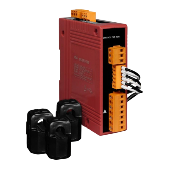
Chapter 1 Introduction 1.1. PM-3133 introduction ICP DAS offers PM-3133 family in a full range of Single-phase and Three-phase smart power meters for power monitoring. The products offer a rich feature set combined with easy-to-integrate communications. With its high accuracy (<0.5%, PF=1), the PM-3133 series products can be applied both on low voltage primary side and/or medium/high voltage secondary side and enable the users to obtain in real time the reliable and accurate energy consumption readings from the monitored equipments while in operation. -
Page 6: Caution
1.2. Caution 1.2.1. Danger The meter contains hazardous voltages, and should never be disassembled. Failing to follow this practice will result in serious injury or death. Any work on or near energized meters, meter sockets, or other metering equipment could induce a danger of electrical shock. -
Page 7: Limitation Of Warranty
1.4.1. Limitation of Warranty This warranty does not apply to defects resulting from unauthorized modification, misuse, or use for reason other than electrical power monitoring. The supplied meter is not a user-serviceable product. PM-3133 User’s Manual v1.13 Last Revised: Apr. 2024 Page: 7 ... -
Page 8: Chapter 2 Specifications
Chapter 2 Specifications 2.1. Specifications Model PM-3133 PM-3133-MTCP AC Power Measurement Wiring 1P2W-1CT, 1P3W-2CT, 3P3W-2CT, 3P3W-3CT and 3P4W-3CT Measurement Voltage 10 ~ 500 V (CAT III) CTØ 10 mm (0.05 A~60 A); CTØ 16 mm (0.1 A~100 A); Measurement Current CTØ... - Page 9 Aux Power +12 ~ 48 VDC or PoE Input Range +12 ~ 48 VDC PoE Pin Assignments: + (Pin 1, 2), V- (Pin 3, 6) Power Consumption Dimensions (W x L x H) 127 mm x 105 mm x 33 mm Environment Operating Temperature -20 ~ +70 °C...
-
Page 10: Naming Rules
2.2. Naming Rules PM-3133 User’s Manual v1.13 Last Revised: Apr. 2024 Page: 10 E-mail: service@icpdas.com Copyright © ICP DAS Co., Ltd. All Rights Reserved. www.icpdas.com... -
Page 11: Chapter 3 Installation
Chapter 3 Installation 3.1. Inspection The instrument is no longer safe when, a) Shows clear signs of damage b) Does not work c) Long storage under extreme conditions d) Damage during shipment 3.2. Safety Please use the soft dry clothes to clean the instrument. Please do not use any chemical or detergent or volatile solvents to clean the instrument, in order to avoid any possibility of the cover damage. - Page 12 Products come with external split type clip-on CT’s. Disconnect the CT’s or use other CT’s is highly prohibited. Please read this operation manual carefully before using. Please re-confirm the measure position. PM-3133 series can be installed as rail mounting mode or embedded, no need to drill a hole or screw to fix it (rail mounting width can up to the length of 35 mm).
-
Page 13: Mounting And Dismounting 7.2
3.2.2. Mounting and Dismounting Mounting Assembly: Place the PM-3133 on the DIN-Rail. Push the front of the PM-3133 toward the mounting surface until it audibly snaps into place. Dismantling: Pull out the latch and then remove the PM-3133 from the DIN-rail ... -
Page 14: Ct's Installation Steps
3.2.3. CT’s installation steps At the bottom of the CT, there is a “K→L” mark. Open the CT clip. Make sure the power current Installation steps finished. direction follow the “K→L” mark on the CT and then close the CT clip. PM-3133 User’s Manual v1.13 Last Revised: Apr. -
Page 15: Chapter 4 Wiring Diagrams
Chapter 4 Wiring Diagrams 4.1. Connection Please firstly check the current input terminal, and then in white black, white black, white black wire sequences (CT1-K, CT1-L, CT2-K, CT2-L,CT3-K,CT3-L). Then connect the CT’s, and close the CT clip. Make sure the arrow direction sign on CT’s follows current flow direction(K→L)... - Page 16 Voltage Input PM-3133 series: Input Voltage up to 500V. For any higher Input Voltage large than 500V, please add the PT (power transformer), and Change PT RATIO setup. Confirm the RST (ABC) phase sequence. Current Input The external CT’s are fragile, please handle with care. The current input of PM-3133 series is in mA range.
-
Page 17: Wiring
4.2. Wiring 1P2W-1CT(PM-3133) 1P3W-2CT(PM-3133) 3P3W-2CT(PM-3133) PM-3133 User’s Manual v1.13 Last Revised: Apr. 2024 Page: 17 E-mail: service@icpdas.com Copyright © ICP DAS Co., Ltd. All Rights Reserved. www.icpdas.com... - Page 18 3P3W-3CT(PM-3133) DIP switch: Wiring mode SW 9 SW 10 3P3W-3CT 3P4W-3CT(PM-3133) DIP switch: Wiring mode SW 9 SW 10 3P4W-3CT PM-3133 User’s Manual v1.13 Last Revised: Apr. 2024 Page: 18 E-mail: service@icpdas.com Copyright © ICP DAS Co., Ltd. All Rights Reserved. www.icpdas.com...
-
Page 19: Chapter 5 Relay Output & Led
Chapter 5 Relay output & LED 5.1. Relay Relay type Power Relay, Form A (SPST N.O.) Operating Voltage Range 250 VAC/30 VDC Max. Load Current 5 A at 25 °C Operate Time 6 ms Release Time 3 ms 5.2. LED Indicator The PM-3133 has 4 LED to indicate the unit power status, RS-485 communication, and power data calculation. -
Page 20: Chapter 6 Modbus-Rtu Communication
Chapter 6 Modbus-RTU Communication 6.1 RS-485 setting Default setting for RS-485: 19200, n, 8, 1 DIP switch (SW1-SW6) is used for Modbus address setting, default is 1, i.e. all OFF For example: Modbus address is 10,find the table of DIP switch 1-6 is ON, OFF, OFF, ON, OFF, OFF 6.1.1 SW1-SW6 setting Setting Modbus-RTU address for communication (1-64) - Page 21 PM-3133 User’s Manual v1.13 Last Revised: Apr. 2024 Page: 21 E-mail: service@icpdas.com Copyright © ICP DAS Co., Ltd. All Rights Reserved. www.icpdas.com...
- Page 22 SW7-SW8 setting PM-3133:For Baud Rate Setting Baud Rate SW 7 9600 bps 19200 bps (Default) 38400 bps 115200 bps Add the Bias Resistor on RS-485 Network for stable signal The RS-485 master is required to provide the bias for PM-3133 series. Otherwise, the tM-SG4 or SG-785 should be added to provide the bias.
-
Page 23: Modbus-Rtu Setting
6.2 Modbus-RTU setting 6.2.1 Specifications Protocol Modbus-RTU Transmission Bits per Byte: Specifications 1 start bit 8 data bits, least significant bit sent first None Parity 1 stop bits Error Check: Cyclical Redundancy Check (CRC) Baud Rate 9600, 19200 (Default), 38400, 115200 Modbus slave address 1-64 (Default = 1) ... - Page 24 IEEE 754 Format Definition of the floating format of the Bits Data Hi Word, Data Hi Word, Data Lo Word, Data Lo Word, Hi Byte Lo Byte Hi Byte Lo Byte SEEE EEEE EMMM MMMM MMMM MMMM MMMM MMMM E - 127 Value = (- 1) x (1.M) x 2 0 <...
-
Page 25: Modbus Register
6.2.2 Modbus Register Modbus Module #1 – Coil: Relay Value Modbus Register Data Default Parameter name Range Comment Modicom value Type Format 0 = OFF DO 0 04097 0x1000 Word Byte 1 = ON 0 = OFF DO 1 04098 0x1001 Word... - Page 26 Only Write, Reset to Factory Re-power the 44109 0x100C Word UInt 0x0055 Settings module after setting Re-power the 0x0055: Auto module after Default Frequency 44110 0x100D Word UInt 0x0064: 50Hz 0x0055 setting or 0x0078: 60Hz changing the frequency Energy Absolute 0: Enable 44113 0x1010...
- Page 27 Modbus Module #3 - Input Register : System Information Modbus Register Data Default Parameter name Range Units Comment Modicom Type value Format 9: 1P2W (HW): set 10: 1P3W wiring by 11: 3P3W2CT hardware Dip 12: 3P3W3CT Switch 13: 3P4W 14: 3P3W2CT Wiring Type 30513...
- Page 28 Modbus Module #4 - Input Register :Power value (Float) Modbus Register Parameter Data Type Range Units Comment name Modicom Format Refer to Q12 0x1100- 0x1101 34353-34354 DWord Float Volt 34355- 34356 0x1102- 0x1103 DWord Float 34357- 34358 0x1104- 0x1105 DWord Float kW_a...
- Page 29 34415-34416 0x113E-0x113F kVA_tot DWord Float 34417-34418 0x1140-0x1141 PF_tot DWord Float 34419-34420 0x1142-0x1143 kWh_tot DWord Float 34421-34422 0x1144-0x1145 kvarh_tot DWord Float 34423-34424 0x1146-0x1147 kVAh_tot DWord Float 34425-34426 0x1148-0x1149 Freq_a DWord Float 45~65 34427-34428 0x114A-0x114B Freq_b DWord Float 45~65 34429-34430 0x114C-0x114D Freq_c DWord Float 45~65...
- Page 30 Modbus Module #5 - Input Register :Power value (Inverse Integer) Modbus Register Parameter Data Range Units Comment name Type Modicom Format 34609- 34610 0x1200-0x1201 DWord UInt32 0.1 Volt 34611- 34612 0x1202-0x1203 DWord UInt32 0.1A 34613- 34614 0x1204-0x1205 kW_a DWord Int32 0.1kW 34615- 34616...
- Page 31 34668-34669 0x123B-0x123C kVA_tot DWord Int32 0.1kVA 34670 0x123D PF_tot Word 0~1000 0.001PF 0~1.000 34671-34672 0x123E-0x123F kWh_tot DWord Int32 ±0~99999999 0.1kWh ±0~9999999.9 34673-34674 0x1240-0x1241 kvarh_tot DWord Int32 ±0~99999999 0.1kvarh ±0~9999999.9 34675-34676 0x1242-0x1243 kVAh_tot DWord Int32 0~99999999 0.1kVAh 0~9999999.9 34677 0x1244 Freq_a Word 45~65 45~65...
- Page 32 Modbus Module #6 - Input Register :Power value (Integer) Modbus Register Parameter Data Range Units Comment name Type Modicom Format 34865- 34866 0x1300- 0x1301 DWord UInt32 0.1 Volt 34867- 34868 0x1302- 0x1303 DWord UInt32 0.1A 34869- 34870 0x1304- 0x1305 kW_a DWord Int32...
- Page 33 34924- 34925 0x133B- 0x133C kVA_tot DWord Int32 0.1kVA 34926 0x133D PF_tot Word 0~1000 0.001PF 0~1.000 34927- 34928 0x133E- 0x133F kWh_tot DWord Int32 ±0~99999999 0.1kWh ±0~9999999.9 34929- 34930 0x1340- 0x1341 kvarh_tot DWord Int32 ±0~99999999 0.1kvarh ±0~9999999.9 34931- 34932 0x1342- 0x1343 kVAh_tot DWord Int32 0~99999999...
-
Page 34: Chapter 7 Modbus-Tcp Communication
Chapter 7 Modbus-TCP Communication 7.1 Default settings Ethernet default settings: IP Address 192.168.255.1 Subnet mask 255.255.0.0 Gateway 192.168.0.1 Port For recovering to default settings, dip Init/Run Switch (SW 4) to Init position for 10 seconds after power on, the settings will be changed as default values. Must dip back to Run position and repower on after settings changed. -
Page 35: Ethernet Configurations
7.1.1 Ethernet configurations In the Power Meter Utility, please select “Modbus TCP” in the Communication Interface. Click “Search” to enter the “Communication Interface Setting” window. Click ”Search” button to search the available power meter. PM-3133 User’s Manual v1.13 Last Revised: Apr. 2024 Page: 35 ... - Page 36 Select the power meter which you want to modify parameters from the meter list, then click ”Configuration” button to setup the meter parameters. After complete all setting, click “OK”, and return to the meter list windows. PM-3133 User’s Manual v1.13 Last Revised: Apr.
-
Page 37: Specifications
7.2 Specifications Modbus-TCP structure Byte 00~05 Byte 06~11 6-byte header RTU Data Modbus-TCP( Byte 00~05) Byte 00 Byte 01 Byte 02 Byte 03 Byte 04 Byte 05 Transaction identifier Protocol identifier Data length Data length upper byte lower byte Transaction identifier = Assign by Modbus/TCP Master (Client) Protocol identifier = 0 Data length (upper byte) = 0 Data length (lower byte) = Depend on the number of the RTU Data bytes... -
Page 38: Connecting The Power And
7.3 Connecting the Power and Host PC (without PoE) Power over Ethernet (PoE): The PM-3133-xxx-MTCP module can be powered by an IEEE802.3af compliant PoE switch. Both Ethernet and power can be carried by an Ethernet cable eliminating the need for additional wiring and power supply. -
Page 39: Chapter 8 Canopen Communication
Chapter 8 CANopen communication 8.1 CANopen setting Default setting for CANopen: Baud rate:125 K b.p.s. , Node ID:1 DIP switch (SW1-SW6) is used for Node ID setting, default is 1, i.e. all OFF For example: Node ID is 10,find the table of DIP switch 1-6 is ON, OFF, OFF, ON, OFF, OFF SW1-SW6 setting ... - Page 40 PM-3133 User’s Manual v1.13 Last Revised: Apr. 2024 Page: 40 E-mail: service@icpdas.com Copyright © ICP DAS Co., Ltd. All Rights Reserved. www.icpdas.com...
- Page 41 SW7-SW8 setting PM-3133:For CANopen Baud Rate Setting Baud Rate SW 7 125 K bps(Default) 250 K bps 500 K bps 1M bps SW9-SW10 setting PM-3133-CPS:Select the different wiring mode (Please select the Software setting, if 1P2W-1CT or 1P3W-2CT is used) Wiring SW 9 SW 10...
-
Page 42: Canopen Protocol
8.2 CANopen Protocol The CANopen is a kind of network protocols evolving from the CAN bus, used on car control system in early days, and has been greatly used in various applications, such as vehicles, industrial machines, building automation, medical devices, maritime applications, restaurant appliances, laboratory equipment &... - Page 43 ccs: client command specified 2: initiate upload request scs: server command specified 2: initiate upload response n : Only valid if e = 1 and s = 1, otherwise 0. If valid, it indicates the number of bytes in d that do not contain data. Bytes [8-n, 7] do not contain segment data.
-
Page 44: Download Sdo Protocol
ccs: client command specified 3: upload segment request scs: server command specified 0: upload segment response t: toggle bit. This bit must alternate for each subsequence segment that is uploaded. The first segment will have the toggle bit set to 0. The toggle bit will be equal for the request and response message. - Page 45 protocol. Otherwise, the download segment protocol will be needed. These two protocols are shown below. ccs: client command specified 1: initiate download request scs: server command specified 3: initiate download response n: Only valid if e = 1 and s = 1, otherwise 0. If valid, it indicates the number of bytes in d that do not contain data.
- Page 46 the least significant bit, and byte 7 contains the most significant bit. e=1, s=1: d contains the data of length 4-n to be downloaded, the encoding depends on the type of the data referenced by index and sub-index. e=1, s=0: d contains unspecified number of bytes to be downloaded. x: not used, always 0 reserved: reserved for further use , always 0 PM-3133 User’s Manual v1.13...
- Page 47 Download Segment Protocol ccs: client command specified 0: download segment request scs: server command specified 1: download segment response seg-data: It is at most 7 bytes of segment data to be downloaded. The encoding depends on the type of the data referenced by index and sub-index. n: It indicates the number of bytes in seg-data that do not contain segment data.
-
Page 48: Abort Sdo Transfer Protocol
8.2.1.3 Abort SDO Transfer Protocol In some conditions, the SDO client or SDO server will terminate the SDO transmission. For example, the value of entries that users want to modify does not exist or is read-only, even users wouldn’t continue the uncompleted SDO protocol under some special situations. - Page 49 Abort Code Description 0503 0000h Toggle bit not alternated. 0504 0000h SDO protocol timed out. 0504 0001h Client/server command specified not valid or unknown. 0504 0002h Invalid block size (block mode only). 0504 0003h Invalid sequence number (block mode only). 0504 0004h CRC error (block mode only).
- Page 50 0800 0023h Object dictionary dynamic generation fails or no object dictionary is present (e.g. object dictionary is generated from file and generation fails because of an file error). PM-3133 User’s Manual v1.13 Last Revised: Apr. 2024 Page: 50 E-mail: service@icpdas.com Copyright ©...
-
Page 51: Pdo Introduction
8.2.2 PDO Introduction 8.2.2.1 PDO COB-ID Parameters Before the real-time data are transmitted by the PDO, it is necessary to check the COB-ID parameter of this PDO in the PDO communication objects. This parameter setting controls the COB-ID of the PDO communication, which is in 32 bits, and each bit with its meaning is given in the table follow. -
Page 52: Transmission Type
Note: 1. Users can also define the PDO COB-ID by themselves. Actually, all COB-ID can be defined by users except the reserved COB-ID described in the table of the section 3.1. It is important to avoid the conflict with the defined COB-ID used in the same node. -
Page 53: Pdo Communication Rule
For the transmission types 254 and 255, the event timer will be used in the TxPDO. The PDO, including the DI value, will be sent when the DI value is changed. And both transmission types will directly trigger an update of the mapped data when receiving the RxPDO. - Page 54 COB-ID: the default PDO COB-ID, or the PDO COB-ID defined by users L: the data length about how many bytes the PDO message has PDO-msg: the real-time data or the data which can be mapped into the PDO mapping objects PM-3133 User’s Manual v1.13 Last Revised: Apr.
-
Page 55: Nmt Introduction
8.2.3 NMT Introduction 8.2.3.1 Module Control Protocol The NMT communication set can be applied for changing the NMT slave status. The following figure shows how to change the different NMT statuses for the PM-3133-CPS. Start Remote Node Protocol cs: NMT command specified 1: start Node ID: the node ID of the NMT slave device Stop Remote Node Protocol... - Page 56 Node ID: the node ID of the NMT slave device PM-3133 User’s Manual v1.13 Last Revised: Apr. 2024 Page: 56 E-mail: service@icpdas.com Copyright © ICP DAS Co., Ltd. All Rights Reserved. www.icpdas.com...
- Page 57 Enter Pre-Operational Protocol cs: NMT command specified 128: enter PRE-OPERATIONAL Node ID: the node ID of the NMT slave device Reset Node Protocol cs : NMT command specified 129: Reset_Node Node ID : the node ID of the NMT slave device PM-3133 User’s Manual v1.13 Last Revised: Apr.
-
Page 58: Error Control Protocol
Reset Communication Protocol cs: NMT command specified 130: Reset_Communication Node ID: the node ID of the NMT slave device 8.2.3.2 Error Control Protocol Error Control Protocol is a kind of the solution to check whether the CANopen device is still alive or not. And its related objects include 0x100C and 0x100D. The 0x100C is the guard time, and the 0x100D is the life time factor. -
Page 59: Pm-3133-Cps
from the NMT slave. After the Node Guarding protocol becomes active, the value of the toggle-bit of the first response will be 0. s: the state of the NMT Slave 4: STOPPED 5: OPERATIONAL 127: PRE_OPERATIONAL 8.2.4 Special Functions for PM-3133-CPS 8.2.4.1 Power Meter Data Table The PM-3133-CPS Manufacturer in the Specific Profile Area defines some entries, which are used for the power meter data. -
Page 60: Pm-3133-Cps
kvarh_b Freq_b kvarh_c Freq_c kvarh_tot Freq_avg 8.3 Object Dictionary of PM-3133-CPS 8.3.1 Communication Profile Area The following tables are regarding each entry of the communication profile area is defined in PM-3133-CPS. For the convenient purpose, all communication entries are divided into several tables. They are “General Communication Entries”, “TxPDO Communication Entries”, and “TxPDO Mapping Communication Entries”. - Page 61 1015h Inhibit time of EMCY UNSIGNED 16 RW 0 1018h largest sub-index supported for UNSIGNED 8 “identity object” vender ID UNSIGNED 32 SDO Communication Entries Sidx Description Type Attr Default 1200h 0h largest sub-index supported UNSIGNED 8 RO 2 for “server SDO parameter” COB-ID form client to server UNSIGNED 32 RO 600h+Node-ID...
- Page 62 event timer UNSIGNED 16 1803h largest sub-index supported UNSIGNED 8 for “receive PDO parameter” COB-ID used by PDO (Tx) UNSIGNED 32 480h+Node-ID transmission type UNSIGNED 8 inhibit time UNSIGNED 16 … … … Reversed event timer UNSIGNED 16 1804h largest sub-index supported UNSIGNED 8 for “receive PDO parameter”...
- Page 63 mapping” read Kw_b data INTEGER 32 3200 0220h read kWh_b data INTEGER 32 3201 0220h 1A02h largest sub-index UNSIGNED 8 supported for “transmit PDO mapping” read Kw_c data INTEGER 32 3200 0320h read kWh_c data INTEGER 32 3201 0320h 1A03h largest sub-index UNSIGNED 8 supported for...
- Page 64 “transmit PDO mapping” read V_avg data INTEGER 32 3202 0420h read I_avg data INTEGER 32 3203 0420h 1A08h largest sub-index UNSIGNED 8 supported for “transmit PDO mapping” read kvar(kvar_a) INTEGER 32 3204 0120h data read kVA(Kva_a) INTEGER 32 3205 0120h data 1A09h largest sub-index...
- Page 65 supported for “transmit PDO mapping” read PF_a data INTEGER 32 3206 0120h read kVAh_a data INTEGER 32 3207 0120h 1A0Dh 0 inhibit time UNSIGNED 8 read PF_b data INTEGER 32 3206 0220h read kVAh_b data INTEGER 32 3207 0220h 1A0Eh 0 largest sub-index UNSIGNED 8 supported for...
-
Page 66: Profile Area
1A12h largest sub-index UNSIGNED 8 supported for “transmit PDO mapping” read kvarh_c data INTEGER 32 3208 0320h read Freq_c data INTEGER 32 3209 0320h 1A13h largest sub-index UNSIGNED 8 supported for “transmit PDO mapping” read kvarh_tot data INTEGER 32 3208 0420h read Freq_avg data INTEGER 32 3209 0420h... - Page 67 kWh_b REAL 32 kWh_c REAL 32 kWh_tot REAL 32 3202h largest sub-index supported for UNSIGNED 8 “Volt” Volt(V_a) REAL 32 Volt(V_b) REAL 32 Volt(V_c) REAL 32 Volt(V_avg) REAL 32 3203h largest sub-index supported for UNSIGNED 8 “Amp” Amp(I_a) REAL 32 Amp(I_b) REAL 32 Amp(I_c)
- Page 68 “kVAh” kVAh_a REAL 32 kVAh_b REAL 32 kVAh_c REAL 32 kVAh_tot REAL 32 3208h largest sub-index supported for UNSIGNED 8 “kvarh” kvarh_a REAL 32 kvarh_b REAL 32 kvarh_c REAL 32 kvarh_tot REAL 32 3209h largest sub-index supported for UNSIGNED 8 “Frequency”...
- Page 69 Mode Harmonic Phase Select UNSIGNED 8 Display Voltage UNSIGNED 8 Number of entries for “System 320Ch UNSIGNED 8 Parameter Setting” Set Energy to Zero UNSIGNED 8 Reset to Factory Settings UNSIGNED 8 Default Frequency UNSIGNED 8 Number of entries for “System 320Dh UNSIGNED 8 Information”...
-
Page 70: Store And Restore Object
8.3.3 Store and Restore Object The users can write the object the value 65766173h to object with index 1010h and subindex 1 to save the application setting, or write the value 64616F6Ch to object with index 1011h and subindex 1 and reboot the module to load the factory default. The following table lists the relative objects which will be stored or restored after writing these two objects: Index... -
Page 71: Appendix 1: Questions & Answers
Appendix 1: Questions & Answers Q1. Can we use the other 5A CT’s (like 300/5) to directly connect to the input current terminals of PM-3133 series? No, because the input current is only mA size on PM-3133 series,definitely not to directly use other 5A CT’s to connect and apply (like100/5…)... - Page 72 Q6. PC and meter cannot make the connection with RS-485? (1) Confirm the Modbus Address, default is 1. (2) Confirm the Band Rate, default is 19200. (3) Confirm the stop bit, default is 1. (4) Confirm the RS-485 connection, make sure the D+/D- is right. (5) Confirm the RS-485 master have to provide the bias for PM-3133 series.
- Page 73 Q9. How to measure the current large than 400A? The CT of PM-3133 maximum range is 400A. If the target is more than 400A, we suggest the solution as follow. For example the target is to measure maximum 800A current. We can measure big CT output and set a CT Ratio.
- Page 74 Q10. Can I use CT's that I currently own with PM-3133 Power Meter? You can use CT's that you currently own with PM-3133P (without CTs) Power Meter. The CT inputs of the PM-3133P can handle a maximum of 333mV (Rogowski coils are not supported) of AC current.
- Page 75 Q11. What is the difference between line to line voltages to line to ground voltage? On a three phase wye connected system line to line voltages will be the voltages between the terminals A - B, B - C, A - C. On a three phase wye connected system line to ground voltages will be the voltages between the terminals A - N, B - N, C - N.
- Page 76 Q12. How to set up [Display Voltage] register value to correctly display line to ground voltage or line to line voltage? The voltage [V_x] register in Modbus register table can be used to show line-to-ground voltage or line-to-line voltage value by setting [Display Voltage] register value. According to different wiring types, it is required to set different [Display Voltage] value.
- Page 77 Q14. How to measure the Voltage large than 500V? For service voltage above 600 Vac, voltage transformers (PTs) are used to step down the voltage to a lower range that will work with a PM-3133 meter. Selecting a Transformer: Selecting the right voltage transformer is simple. Review the following considerations to determine the best fit for your application.
- Page 78 Q15. The Power Meter can be connected to a remote display (via RS-485). A: Power Meter can be connected to VPD-13x or VPD-14x series via RS-485: B: Two Masters Share One Slave (via tSH-735): This function allows two master devices connected to different serial ports to share slave devices.
Need help?
Do you have a question about the PM-3133-400P and is the answer not in the manual?
Questions and answers