Sign In
Upload
Manuals
Brands
ICP DAS Manuals
Measuring Instruments
PMC-5151
ICP DAS PMC-5151 Manuals
Manuals and User Guides for ICP DAS PMC-5151. We have
3
ICP DAS PMC-5151 manuals available for free PDF download: User Manual, Quick Start Manual, Quick Start
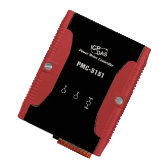
ICP DAS USA PMC-5151 User Manual (340 pages)
Power Meter Concentrator
Brand:
ICP DAS USA
| Category:
Measuring Instruments
| Size: 9.73 MB
Table of Contents
Table of Contents
3
1 System Introduction
14
Figure1-1 : PMC/PMD System Architecture
15
2 Before Installation
18
3 System Login
19
Figure3-1 : PMC/PMD Login Page
19
4 System Main Page
20
Figure4-1 : PMC/PMD Main Page
20
System Function Area
21
Rules Management Toolbar
21
Figure4-2 : System Function Area (Login as a Administrator)
21
Figure4-3 : System Function Area(Login as a General User)
21
Figure4-4 : Rules Management Toolbar (Login as a Administrator)
21
Figure4-5 : Rules Management Toolbar (Login as a General User)
22
Figure4-6 : Confirm to Clear Settings
22
Figure4-7 : Confirm to Load Settings
22
Figure4-8 : Confirm to Save Settings
23
Figure4-9 : Confirm to Logout (the Settings Are Saved)
23
Figure4-10 : Confirm to Logout (the Settings Are Not Saved)
23
Real-Time Information Area
24
System Function Toolbar
24
Figure4-11 : Real-Time Information Area
24
Figure4-12 : Real-Time Information List
24
Sub-Function Area
25
Data Review/System Setting Area
25
Figure4-13 : Current Function Path
25
Figure4-14 : Power Data Overview Page
26
Figure4-15 : Select the Classification of Power Data
26
Figure4-16 : Display Power Data of the Selected Classification
27
5 Main Page
28
Power Meter Information
28
Power Meter Information Overview
28
Figure5-1 : Information Display Options on Main Page
28
Figure5-2 : Power Meter Information Overview
29
Figure5-3 : the Attribute of PM-3133 Power Meter
29
Figure5-4 : the Attribute of PM-3133-MTCP Power Meter
30
Figure5-5 : Real Time Power Information of PM-3133
30
Figure5-6 : Real Time Power Information of PM-3114
31
Figure5-7 : Real Time Power Information of PM-3112
31
Power Meter Statistics Information Overview
32
Figure5-8 : Power Meter Statistics Information
32
Other Information
33
I/O Information
33
Figure5-9 : Power Meter Other Information Page
33
Figure5-10 : Power Meter I/O Information Page
33
Power Data Information
34
Overview
34
Figure5-11 : Power Data Overview Mode
34
Group Overview
35
Figure5-12 : Change Display List Button
35
Figure5-13 : the Power Meter List
35
Figure5-14 : Power Data Group Overview Mode
35
Realtime Chart
36
Power Meter Mode
36
Figure5-15 : Realtime Chart (Power Meter Mode)
37
Group Mode
38
Figure5-16 : Realtime Chart (Group Mode)
39
Historical Chart
40
Figure5-17 : Historical Chart Inquiry
40
Figure5-18 : Historical Data Chart for Power Data
41
Historical Data Report
42
Figure5-19 : Historical Data Table for Power Data
42
Figure5-20 : Historical Data Report Inquiry
42
Figure5-21 : Daily Report for PM-3133
44
Figure5-22 : Daily Report for PM-3114
44
Figure5-23 : "Total Accu. Electricity" Report for Power Meters Group
44
Historical Electricity Analysis
45
Energy Usage Analysis by Trend
45
Figure5-24 : Energy Usage Analysis by Trend
45
Figure5-25 : Inquiry by Group Mode
46
Figure5-26 : Inquiry by User-Defined Mode
46
Energy Usage Analysis by Time Period
47
Figure5-27 : PM-3114 Energy Usage Analysis Trend Chart
47
Figure5-28 : Energy Usage Analysis by Time Period
48
Energy Usage Breakdown by Circuit/Group
49
Figure5-29 : Time Histogram Chart for PM-3114 Loop 1
49
Figure5-30 : Energy Usage Breakdown by Circuit/Group
49
Figure5-31 : Inquiry by Group Mode
50
Figure5-32 : Energy Usage Breakdown by Circuit/Group Chart
51
PUE Information
52
Real-Time
52
History
52
Figure5-33 : PUE Information - Realtime
52
Figure5-34 : PUE Information - History(1)
53
Figure5-35 : PUE Information - History(2)
53
I/O Information
54
Figure5-36 : I/O Information(Login as Administrator)
54
Figure5-37 : I/O Information(Login as General User)
54
I/O Realtime Chart
55
Figure5-38 : I/O Realtime Chart
55
I/O Historical Chart
56
Figure5-39 : I/O Channel Historical Chart
56
Figure5-40 : User-Defined Historical Chart
56
Figure5-41 : I/O Historical Data Chart
57
Event Log
58
Figure5-42 : Event Log Information Display
58
Polling Time Information
59
Modbus Table Information
59
Figure5-43 : Polling Time Information
59
Figure5-44 : the Interface of Modbus Table Information
59
UID Information
60
Figure5-45 : Inquiry Result of Modbus Table Information
60
Figure5-46 : Power Meter UID Information Page
61
6 System Setting
62
Figure6-1 : System Setting Overview Page
62
Time Setting
63
Figure6-2 : Time Setting Page
63
Figure6-3 : Time Synchronization Setting
64
Network Setting
65
Figure6-4 : PMC-52Xx/Pmd Network Setting Page
65
Figure6-5 : PMC-5151 Network Setting Page
66
Figure6-6 : Signal Strength Level and IP Address for Mobile Network
67
Figure6-7 : DDNS Setting Page
68
VPN Setting (this Function Is for PMC-5151 Only.)
69
Figure6-8 : Iotstar Connection Setting Page
69
Figure6-9 : Setting Interface of VPN Function
70
Figure6-10 : Setting Interface of VPN Function
71
Figure6-11 : Security Setting Interface of VPN Function
72
SNMP Setting
73
Figure6-12 : SNMP Setting Page
73
Figure6-13 : SNMP Manager List
74
Figure6-14 : the Address Setting for SNMP Manager
74
Figure6-15 : the Working Model Setting for SNMP Manager
74
Figure6-16 : Save the SNMP Manager Setting
75
Security Setting
76
Figure6-17 : Security Setting Page
76
Figure6-18 : Password Setting Page
77
Figure6-19 : Local FTP Server Setting Page
77
I/O Interface Setting
78
Figure6-20 : Idle Time Setting Page
78
Figure6-21 : I/O Interface Setting Page
78
Figure6-22 : Function Setting to Connect to HMI or SCADA
79
Figure6-23 : Function Setting to Connect to Modbus RTU Slave Device
80
Other Setting
81
Figure6-24 : I/O Function Setting about LAN
81
Figure6-25 : Other Setting Page
81
Power Meter Group Setting
82
Group and Subgroup Viewing
82
Figure6-26 : Power Meter Group Setting
82
Group and Subgroup Setting
83
Figure6-27 : Group and Subgroup Viewing
83
Figure6-28 : Group Setting
83
Figure6-29 : Subgroup Setting
83
Group and Subgroup Configuration
84
Figure6-30 : Subgroup Setting Window
84
Figure6-31 : Configurations for Subgroup
84
Setup the Loops/Phases of the Subgroup
85
Figure6-32 : Loops/Phases of Subgroup Setting
85
Loop/Phase of Group Configuration
86
Figure6-33 : Choose Loops/Phased of Subgroup
86
Figure6-34 : Add Loops/Phases for Subgroup
86
Figure6-35 : Configurations for Loops/Phased of Subgroup
86
Firmware Update
88
Figure6-36 : Firmware Update(1)
88
Figure6-37 : Firmware Update(2)
89
Figure6-38 : Firmware Update(3)
89
Figure6-39 : Firmware Update(4)
89
Figure6-40 : Firmware Update(5)
90
Figure6-41 : Firmware Update(6)
90
7 Power Meter & I/O Module Setting
91
Figure7-1 : Meter / Module Setting Page
91
Power Meter Setting
92
Figure7-2 : Power Meter Setting Page
92
Figure7-3 : the "Scan" Button to Search Power Meter
93
Figure7-4 : Set up the Scanning Range for the Power Meters
93
Scan to Add Modbus RTU Power Meters
93
Add Modbus RTU Power Meter Manually
94
Figure7-5 : Scanning the Power Meters
94
Figure7-6 : the Power Meter List after Scan Operation
94
Figure7-7 : Select the Actual Power Meter Connected to PMC/PMD
94
Figure7-8 : Set up the no and Address of the Power Meter
95
Figure7-9 : Select Modbus RTU Power Meter Model
95
Add Modbus TCP Power Meter Manually
96
Figure7-10 : Add the Modbus RTU Power Meter Manually
96
Figure7-11 : Add Modbus TCP Power Meter
96
Figure7-12 : Select Modbus TCP Power Meter Model
97
Figure7-13 : Add the Modbus TCP Power Meter Manually
97
Figure7-14 : Power Meter List Interface
97
Power Meter List Interface
97
Figure7-15 : PM-3133 Setting Page
98
Modbus RTU Power Meter Setting
98
Figure7-16 : PM-3114 Setting Page
100
Figure7-17 : PM-3114-MTCP Setting Page
101
Modbus TCP Power Meter Setting
101
XW-Board/XV-Board Setting (PMD Series Does Not Support this Function.)
103
XW-Board/XV-Board DI Channel Settings
103
Figure7-18 : XW-Board Setting Page
103
XW-Board/XV-Board DO Channel Settings
104
Figure7-19 : XW-Board DI Attribute Setting Page
104
Figure7-20 : XW-Board DO Attribute Setting Page
105
XW-Board/XV-Board AI Channel Settings
106
Figure7-21 : XW-Board AI Attribute Setting Page
106
Figure7-22 : AI Deadband Operation(> or >= a Numerical Value)
107
Figure7-23 : AI Deadband Operation(< or <= a Numerical Value)
108
Figure7-24 : AI Deadband Operation(= a Numerical Value)
108
XW-Board/XV-Board AO Channel Settings
109
Figure7-25 : XW-Board AO Attribute Setting Page
109
I/O Module Setting
110
Figure7-26 : I/O Module Setting Page
110
Figure7-27 : the "Scan" Button to Search M-7000/DL Module
111
Figure7-28 : Set up the Scanning Range for the M-7000/DL Module
111
Scan to Add ICP das M-7000/DL Modules
111
Figure7-29 : Scanning the M-7000/DL Modules
112
Figure7-30 : the M-7000/DL List after Scan Operation
112
Figure7-31 : Select the Actual M-7000/DL Modules Connected to PMC/PMD
112
Add Modbus RTU Module (or M-7000/DL Module) Manually
113
Figure7-32 : Set up the no and Address of the Modbus RTU Module
113
Figure7-33 : Select the Model of the Modbus RTU Module
113
Add Modbus TCP Module Manually
114
Figure7-34 : Add the Modbus RTU Module Manually
114
Figure7-35 : Add Modbus TCP Module
114
Figure7-36 : Add the Modbus RTU Power Meter Manually
115
Figure7-37 : Modbus Module List Interface
115
I/O Module List Interface
115
M-7000/DL Module Setting
116
Figure7-38 : M-7000 DI Channel Setting Page
117
Figure7-39 : M-7000/DL DO Channel Setting Page
118
Figure7-40 : M-7000/DL AI Channel Setting Page
119
Figure7-41 : M-7000 AO Channel Setting Page
120
Figure7-42 : Modbus RTU Slave Module Setting Page
121
Modbus RTU Module Setting
121
Figure7-43 : Coil Output Setting Page
123
Figure7-44 : Coil Output Setting Example for Modbus RTU Module
124
Figure7-45 : Discrete Input Setting Page
125
Figure7-46 : Discrete Input Setting Example for Modbus RTU Module
126
Figure7-47 : Input Register Setting Page
127
Figure7-48 : Input Register Setting Example for Modbus RTU Module
129
Figure7-49 : Holding Register Setting Page
130
Figure7-50 : Input Register Setting Example for Modbus RTU Module
132
Figure7-51 : Modbus TCP Slave Module Setting Page(1)
133
Modbus TCP Module Setting
133
Figure7-52 : Modbus TCP Slave Module Setting Page(2)
134
8 Logger Setting
135
Figure8-1 : Data Logger Setting Page
135
Data Logger Setting
136
Figure8-2 : Data Logger Setting Page
136
Event Logger Setting
139
Figure8-3 : Event Logger Setting Page
139
FTP Upload Setting
140
Figure8-4 : FTP Upload Setting Page
140
Cloud Upload Setting
141
Figure8-5 : Cloud Upload Setting Page
141
The Path of Data Log File
142
The Format of the Power Data Logger File
144
The Format of the Power Report File
146
The Format of User-Defined Data File
149
9 Iot Platform Setting
150
Microsoft Azure Setting
150
Figure9-1 : Microsoft Azure Setting Page
150
Figure9-2 : Microsoft Azure Publish Message Setting Page
152
Figure9-3 : "User-Defined Data" Setting Interface of Iot Platform
153
Figure9-4 : Microsoft Azure Subscribe Topic Setting Page
153
IBM Bluemix Setting
155
Figure9-5 : IBM Bluemix Setting Page
155
Figure9-6 : IBM Bluemix Subscribe Message Setting Page
156
MQTT Setting
157
Broker Setting
157
Figure9-7 : MQTT Setting Page (Broker)
158
Figure9-8 : MQTT Broker Parameter Setting Page
158
Figure9-9 : Publish Message and Subscribe Topic Setting Page
160
Figure9-10 : Publish Message Setting Page
161
Topic Import/Export Setting
163
Figure9-11 : Subscribe Topic Setting Page
163
10 Advanced Setting
166
Email Setting
166
Figure10-1 : Email Setting Page
167
Figure10-2 : Email Setting Page(Name & Description))
167
Figure10-3 : Email Setting Page(SMTP Server)
168
Figure10-4 : Email Setting Page(Email Address)
168
Figure10-5 : Email Setting Page(Email Content)
169
SMS Setting
170
SMS Alarm Setting
170
Figure10-6 : SMS Setting Page (1)
170
Figure10-7 : SMS Setting Page (2)
171
SMS Command Setting
172
Figure10-8 : SMS Command Setting Page (1))
172
Figure10-9 : SMS Command Setting for GET Command
174
Figure10-10 : SMS Command Setting for SET Command
174
Figure10-11 : SMS Command List
174
SNMP Trap Setting
176
Figure10-12 : SNMP Trap Setting Page
176
Figure10-13 : SNMP Trap Parameter Setting Page
176
Figure10-14 : "Channel Data"Type Setting Page
177
Figure10-15 : Example of "Channel Data" Type Variable Binding List
178
Figure10-16 : "User-Defined Data" Type Setting Page
178
Figure10-17 : "User-Defined Data" Interface in Edit Mode
179
Figure10-18 : "User-Defined Data" Interface in View Mode
180
Figure10-19 : SNMP Trap Setting with Variable Bindings List
180
LINE Notify Setting
181
Message Setting
181
Figure10-20 : LINE Notify Message Setting Page (1)
181
Figure10-21 : LINE Notify Message Setting Page (2)
182
Figure10-22 : LINE Notify Message Setting Page (3)
182
Chat Room Setting
183
Figure10-23 : LINE Notify Message Setting Page (4)
183
Figure10-24 : LINE Notify Chat Room Setting Page (1)
184
Figure10-25 : LINE Notify Chat Room Setting Page (2)
184
Figure10-26 : LINE Notify Chat Room Setting Page (3)
185
Figure10-27 : LINE Notify Chat Room Setting Page (4)
185
Figure10-28 : LINE Notify Chat Room Setting Page (5)
185
Timer Setting
186
Figure10-29 : Timer Creating Page
187
Figure10-30 : Timer Setting Page(Assign Period)
187
Schedule Setting
188
Figure10-31 : Timer Setting Page(Internal Register)
188
Figure10-32 : Schedule Setting Page
188
Figure10-33 : Calendar Mode of Schedule Setting
189
Figure10-34 : Repeat Mode of Schedule Setting
190
PUE Setting
191
Figure10-35 : PUE Setting Page(1)
192
Internal Register Setting
193
Figure10-36 : PUE Setting Page(2)
193
Figure10-37 : Internal Register Setting Page(1)
194
Figure10-38 : Internal Register Setting Page(2)
194
11 Rules Setting
196
Figure11-1 : Rules Overview Page
196
Figure11-2 : Rules Setting Page
197
IF Condition Setting
198
ICP das Module
199
Figure11-3 : DI Condition Setting Page
199
Figure11-4 : DI Counter Condition Setting Page
200
Figure11-5 : AI Condition Setting Page
201
Modbus Module
203
Figure11-6 : Discrete Input Condition Setting Page
203
Figure11-7 : Coil Output Condition Setting Page
204
Figure11-8 : Input Register Condition Setting Page
205
Figure11-9 : Holding Register Condition Setting Page
205
Power Meter
206
Figure11-10 : Power Meter Condition Setting Page
206
Microsoft Azure
207
Figure11-11 : Microsoft Azure Connection Status Condition Setting
207
IBM Bluemix
208
Figure11-12 : Microsoft Azure Subscribe Message Condition Setting
208
Figure11-13 : IBM Bluemix Connection Status Condition Setting
208
Mqtt
209
Figure11-14 : IBM Bluemix Subscribe Message Condition Setting
209
Figure11-15 : Broker Connection Status Condition Setting
210
Figure11-16 : Subscribe Topic Condition Setting
210
Connection Status
211
Timer
211
Figure11-17 : Connection Status Condition Setting Page
211
Schedule
212
Mobile Network Signal Strength
212
Figure11-18 : Timer Condition Setting Page
212
Figure11-19 : Schedule Condition Setting Page
212
FTP Upload Status
213
Figure11-20 : Mobile Network Signal Strength Condition Setting Page
213
Figure11-21 : FTP Upload Status Condition Setting Page
213
SD Card Status
214
Rule Status
214
Figure11-22 : SD Card Status Condition Setting Page
214
Figure11-23 : Rule Status Condition Setting Page
214
Internal Register
215
Figure11-24 : Internal Register Condition Setting Page
215
THEN/ELSE Action Setting
216
ICP das Module
217
Figure11-25 : DI Counter Action Setting Page
217
Figure11-26 : DO Action Setting Page
217
Figure11-27 : AO Action Setting Page
218
Modbus Module
220
Figure11-28 : Coil Output Action Setting Page
221
Figure11-29 : Holding Register Action Setting Page
221
Power Meter
222
Microsoft Azure
222
Figure11-30 : Power Meter Relay Action Setting Page
222
IBM Bluemix
223
Figure11-31 : Microsoft Azure Function Status Action Setting
223
Figure11-32 : Microsoft Azure Publish Message Action Setting
223
Figure11-33 : IBM Bluemix Function Status Action Setting
224
Figure11-34 : IBM Bluemix Publish Message Action Setting
224
Mqtt
225
Figure11-35 : Broker Function Action Setting Page
225
Figure11-36 : Publish Message Action Setting Page
225
Timer
226
Email
226
Figure11-37 : Timer Action Setting Page
226
SMS Alarm
227
Figure11-38 : Email Action Setting Page
227
Figure11-39 : SMS Alarm Action Setting Page
227
SNMP Trap
228
LINE Notify
228
Figure11-40 : SNMP Trap Action Setting Page
228
Data Logger
229
Rule Status
229
Figure11-41 : LINE Notify Action Setting Page
229
Figure11-42 : Data Logger Action Setting Page
229
Internal Register
230
Figure11-43 : Rule Status Action Setting Page
230
Figure11-44 : Internal Register Action Setting Page
230
Appendix I:modbus Address Table
232
Appendix II:reset to Factory Default Setting and Send Password to Administrator
310
Appendix III:setup the GTM-203M-3GWA with PMC-5151 and PMD
313
Appendix IV:the Configuration Setting of M-7000/DL Module
314
Appendix V:the AI Channel Setting of XW310C
318
Appendix VI:the SNMP Variables for PMC/PMD
319
Appendix VII:change the Value of Output Channel of Module or Internal Register by MQTT Protocol
330
Appendix VIII:the JSON Format for the Communication with Iot Platform
332
Appendix IX:pmc-52Xx/Pmd Connection Setting for Iotstar
337
Advertisement
ICP DAS USA PMC-5151 Quick Start Manual (8 pages)
Brand:
ICP DAS USA
| Category:
Measuring Instruments
| Size: 0.69 MB
ICP DAS USA PMC-5151 Quick Start (4 pages)
Brand:
ICP DAS USA
| Category:
Network Hardware
| Size: 5.12 MB
Advertisement
Advertisement
Related Products
ICP DAS USA PMC series
ICP DAS USA PMC-5231
ICP DAS USA PMC-5231M-3GWA
ICP DAS USA PMC-5231M-4GE
ICP DAS PMC-5231M-4GC
ICP DAS USA PMC-523 Series
ICP DAS USA PMC-224 PMD Series
ICP DAS USA PM-3133P-CPS
ICP DAS USA PM-3133-MTCP
ICP DAS USA PM-4324-100P-CPS
ICP DAS Categories
Control Unit
I/O Systems
Controller
Media Converter
PCI Card
More ICP DAS Manuals
Login
Sign In
OR
Sign in with Facebook
Sign in with Google
Upload manual
Upload from disk
Upload from URL