Burkert 8692 Quick Start Manual
Positioner and process controller
Hide thumbs
Also See for 8692:
- Operating instructions manual (252 pages) ,
- Quick start manual (116 pages) ,
- Supplement to operating instructions (28 pages)
Table of Contents
Advertisement
Quick Links
Download this manual
See also:
Quick Start Manual
Advertisement
Table of Contents

Related Manuals for Burkert 8692


Summary of Contents for Burkert 8692
- Page 1 Type 8692, 8693 Positioner and process controller Positioner und Prozessregler Positionneur et régulateur de process Quickstart...
- Page 2 We reserve the right to make technical changes without notice. Technische Änderungen vorbehalten. Sous réserve de modifications techniques. © Bürkert Werke GmbH & Co. KG, 2008 - 2018 Quickstart 1802/06_EU-ML_00805803 / Original DE...
-
Page 3: Table Of Contents
................ 12 13.2 Starting-up Type 8692 ..........31 7.1 Description of the operating and display elements ... 12 13.3 Starting-up Type 8693 ..........33 7.2 Function of the keys ............. 13 14 safety end positions ..........35 operating states ............14 15 disassemBly of type 8692/8693 ........36 8.1 Changing the operating state ........14 English... -
Page 4: Quickstart Guide
Type 8692, 8693 Quickstart guide QuicksTarT guide 15.1 Disconnecting the pneumatic connections ....36 15.2 Disconnecting electrical connections......37 The quickstart guide contains the most important information and 15.3 Removing Type 8692/8693 ........37 notes regarding the use of the device. A detailed description can be found in the operating instructions for Type 8692/8693. 16 accessories ..............38 Keep the quickstart guide in a location which is easily accessible to 16.1 Communications software......... 38 every user and make it available to every new owner of the device. 16.2 USB interface ............38 16.3 Download ..............38 important safety information! 17 transport, storage, disposal ......... -
Page 5: Symbols
Type 8692, 8693 Authorized use Symbols auThorized use The following symbols are used in these instructions. non-authorized use of the positioner type 8692 and the process controller type 8693 can be dangerous to people, Danger! nearby equipment and the environment. Warns of an immediate danger! The device is designed to be mounted on pneumatic actuators ▶ Failure to observe the warning will result in a fatal or serious of process valves for the control of media. -
Page 6: Basic Safety Instructions
Type 8692, 8693 Basic safety instructions Basic safeTy insTrucTions ▶ After an interruption in the electrical or pneumatic supply, ensure that the process is restarted in a defined or controlled These safety instructions do not make allowance for any manner. • Contingencies and events which may arise during the assembly, ▶ The general rules of technology must be observed for appli- operation, and maintenance of the devices. cation planning and operation of the device. • Local safety regulations – the operator is responsible for observing To prevent damage to the device: these regulations, also in relation to the installation personnel. ▶ When unscrewing and screwing the housing jacket (with transparent cap) in, do not hold the actuator but the electrical connection housing of Type 8692/8693. risk of injury from high pressure in the system/device. ▶ Do not supply the pilot air port with aggressive or flammable ▶ Before working on the system or device, switch off the pres- media or fluids. -
Page 7: General Information
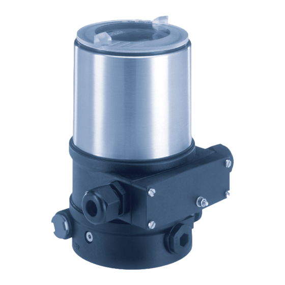
Fig. 1: Structure, Type 8692/8693 with process valve And also on the Internet at: www.burkert.com The positioner Type 8692 and the process controller Type 8693 are electropneumatic position controllers for pneumatically actuated Warranty control valves with single-acting or double-acting actuators. The warranty is only valid if the Types 8692/8693 are used as Together with the pneumatic actuator the positioner and process intended in accordance with the specified application conditions. controller form an optical and functional unit. The control valve systems can be used for a wide range of control Information on the Internet tasks in fluid technology and, depending on the application con- The operating instructions and data sheets for Types 8692/8693 ditions, different process valves from the Bürkert range can be can be found on the Internet at: combined with the positioner or the process controller. Angle seat... -
Page 8: Functions
Type 8692, 8693 System description Functions Transparent cap (below control module with display Type 8692 - Positioner (position controller) and keys) The position of the actuator (stroke) is regulated according to the Housing jacket position set-point value. The position set-point value can be specified by an external standard signal (or via field bus). Electrical connection housing (Connection option with circular Type 8693 - Process controller plug-in connector) The process controller is linked to a control circuit. The position Pressure limiting valve set-point value of the valve is calculated from the process set- point value and the process actual value via the control param- eters Exhaust air port (PID controller). The process set-point value can be set by an (Label: 3) external signal. Pilot air port (Label: 1) Electrical connection housing (Connection option with connection terminals) Additional exhaust air port (Label: 3.1) only for Types 23xx and 2103 with pilot-controlled control system for a high air flow rate from actuator size ø 125 / 130 Air intake filter Fig. 2:... -
Page 9: Technical Data
Type 8692, 8693 Technical data Technical daTa Ambient temperature: T he permitted temperature range is given on the rating plate of the Conformity device. Types 8692/8693 conform to the EU directives according to the EU Degree of protection Declaration of Conformity. Evaluated by the manufacturer: Evaluated by UL: Standards IP65 / IP67 according to EN 60529 * UL Type 4x Rating * The applied standards which are used to demonstrate compliance * only if cables, plugs and sockets have been connected correctly and with the EU Directives are listed in the EU-Type Examination Cer- in compliance with the exhaust air concept (see Chapter "10.5 Pneu- tificate and/or the EU Declaration of Conformity. -
Page 10: Mechanical Data
Type 8692, 8693 Technical data 6.5.1 UL additional label Oil content Quality class X: max. 25 mg/m3 example: Temperature range control medium 0 ... + 50 °C Degree of protection Type 4X enclosure Pressure range NEC Class 2 only Circuit with limited power control medium 3 ... 7 bar Supply voltage: 24V Supply voltage device Air flow rate pilot valve 7 l / min (for aeration and deaer- ation) Fig. 4: UL additional label (example) - value according to definition for pressure drop from 7 to 6 bar Mechanical data... -
Page 11: Electrical Data
Type 8692, 8693 Technical data Electrical data Input data for set-point value signal 0/4 ... 20 mA: I nput resistance 180 Ω Warning! Resolution 12 bit Only circuits with limited power may be used for UL 0 ... 5/10 V: I nput resistance 19 kΩ approved components according to “NEC Class 2”. Resolution 12 bit Analogue feedback Protection class 3 as per DIN EN 61140 (VDE 0140-1) Max. current 1 0 mA Connections C able gland M16 x 1.5, SW22 (for voltage output 0 ... 5/10 V) (clamping area 5 ... 10 mm) Burden (load) 0 ... 560 Ω with connection terminals for cable cross- (for current output 0/4 ... 20 mA) sections 0.14 ... 1.5 mm² (24 V DC) or... -
Page 12: Operation
Type 8692, 8693 Operation operaTion display elements of the Description of the operating and setting level: display elements Menu designation display elements of the process level: M A I N Save symbol actuator INPUT Submenu Symbol for position control X.TUNE ADD.FUNCTION Symbol for process control EXIT ENTER... -
Page 13: Function Of The Keys
Type 8692, 8693 Operation Function of the keys function of the keys on the setting level: The function of the 4 keys in the control field differs depending function of the on the operating state (AUTOMATIC or MANUAL) and description of the function keys operating level (process level or setting level). Arrow key Scroll up in the menus The function of the keys is displayed in the gray text field which is above the key. Increase numerical values MENU Arrow key Scroll down in the menus function of the keys on the process level:... -
Page 14: Operating States
Type 8692, 8693 Operating states operaTing sTaTes Displays in the AUTOMATIC operating state Type 8692/8693 has 2 operating states: AUTOMATIC and MANUAL. type 8692 description of the display type 8693 AUTOMATIC Actual position of the valve In the AUTOMATIC operating state actuator (0 ... 100%) normal controlled operation is implemented. MENU CMD MANU MENU SP/PV CMD MANU CMD/POS (The symbol for AUTOMATIC Set-point position of the valve is shown on the display. (A bar runs... -
Page 15: Master Code
Type 8692, 8693 Operating states type 8692 description of the display type 8693 type 8692 description of the display type 8693 Automatic linearization of the p.lin Graphical display of SP and process characteristics PV with time axis SP / PV (t) MENU HOLD MENU P.TUNE CMD/POS Simultaneous display of the Graphical display of POS set-point position and the and CMD with time axis actual position of the valve actuator (0 ... 100 %) -
Page 16: Operating Levels
Type 8692, 8693 Operating levels insTallaTion operaTing levels Only for positioners and process controllers without There is the process level and the setting level for the operation pre-assembled process valve. and setting of type 8692/8693. process level: 10.1 Installation of devices for the Ex area The running process is displayed and operated on this level. When installing devices in the explosion-protected area, observe the Operating state: A UTOMATIC – Displaying the process data "ATEX manual for use in the Ex area" enclosed with the Ex-devices. MANUAL – M anually opening and closing the valve 10.2 Safety instructions setting level: Danger! The basic settings for the process are made on the setting level. -
Page 17: Installation On Process Valves, Types 2103, 2300 And 2301
Type 8692, 8693 Installation 10.3 Installation on process valves, types During the installation, the collets of the pilot air ports must 2103, 2300 and 2301 not be fitted to the actuator. note! When mounting on process valves with a welded body, → Aligning actuator with type 8692/8693: follow the installation instructions in the operating instruc- 1. A lign the pilot air ports of the actuator with the tions for the process valve. -
Page 18: Installation On Process Valves, Series 26Xx And 27Xx
Type 8692, 8693 Installation 10.4 Installation on process valves, series Guide rail 26xx and 27xx The installation of the switch spindle is described in the operating instructions for Type 8692/8693. You can find the instructions on the Bürkert homepage. → Place Type 8692/8693 onto the actuator. In doing so, align the puck of the actuator with the guide rail of Type 8692/8693 (see "Fig. 10"). Puck Guide rail Fig. 9: Aligning the puck note! damage to the pcB or malfunction! ▶ Ensure that the puck lies flat on the guide rail. → Push Type 8692/8693 without turning it onto the actuator until no gap is visible on the form seal. - Page 19 ▶ Maximum tightening torque: 1.5 Nm. "In rest position" means that the pilot valves of Type 8692/ → Attach Type 8692/8693 to the actuator using the two side 8693 are isolated or not actuated. fastening screws. In doing so, tighten the screws only hand-tight (max. tightening torque: 1.5 Nm). If the ambient air is humid, a hose can be connected...
-
Page 20: Pneumatic Connection
Type 8692, 8693 Installation 10.5 Pneumatic connection control function pneumatic connection type 8692, 8693 with actuator Danger! pilot air pilot air port actuator risk of injury from high pressure in the system/device. outlet ▶ Before working on the system or device, switch off the pres- types 8692 sure and vent/drain lines. and 8693... -
Page 21: Electrical Installation
Type 8692, 8693 Electrical installation elecTrical insTallaTion Exhaust air There are 2 connection options for Type 8692/8693: port • Multi-pole with circular plug-in connector Label: 3 • Cable gland with connection terminals Pilot air port Label: 1 signal values Additional Operating voltage: 24 V DC exhaust air port Label: 3.1 Set-point value (process/position controller): 0 ... 20 mA; 4 ... 20 mA (only for Types 23xx and 2103 with pilot-controlled control system 0 ... 5 V; 0 ... 10 V for a high air flow rate from actuator size ø 125 / 130) Actual value Fig. 12: Pneumatic connection (only process controller): 4 ... 20 mA;... -
Page 22: Electrical Installation With Circular Plug-In Connector
Type 8692, 8693 Electrical installation designation of the circular plug-in connectors: Warning! X1 - m12 circular connector, risk of injury from improper installation! 8-pole ▶ Installation may be carried out by authorized technicians Input signals for the control only and with the appropriate tools! center risk of injury from unintentional activation of the system and Output signals from the... - Page 23 Operating voltage ** Can be adjusted via software (see operating instructions * The indicated colors refer to the connection cable available as an Type 8692/8693 "Setting the input signal"). accessory (918038). Tab. 5: X5 - M8 circular connector, 4-pole (process actual value) - Type Tab.
- Page 24 Type 8692, 8693 Electrical installation *** F or reasons of wire resistance compensation, note! connect the Pt 100 sensor via 3 wires. Breakage of the pneumatic connection pieces due to rota- Always bridge Pin 3 and Pin 4 on the sensor. tional impact! ▶ When unscrewing the housing jacket, do not hold the actua- tor but the electrical connection housing above. X4 - M8 socket, 4-pole (proximity switch) - option only → Hold the electrical connection housing in place.
- Page 25 Type 8692, 8693 Electrical installation 2. Setting the proximity switch Bottom end position for control function a or top end position for control function B The proximity switch can be set to the bottom or the top → Switch on operating voltage at the proximity switch end position. The handling of the settings differs for the connector. various control functions. → Using a screwdriver, set proximity switch at the setting screw to end position. Setting screw → Switch off operating voltage at the proximity switch connector. Bottom end position for control function i →...
- Page 26 Type 8692, 8693 Electrical installation → Attach electronics module carefully and press down evenly top end position for control function a and i or bottom end position for control function B until the holders snap into place. → Check that the seal is correctly positioned on the housing jacket. → Set jumper (see "Fig. 15: Setting the proximity switch"witch"). → Connect the pilot air. Warning! Seal valve moves after electrical voltage has been connected!
-
Page 27: Electrical Installation With Cable Gland
Type 8692, 8693 Electrical installation 11.3 Electrical installation with cable gland Connection cover Switch procedure: → Loosen the 4 screws of the connection cover and remove the cover. The connection terminals are now accessible. → Push the cables through the cable gland. → Connect the wires. → Tighten the union nut of the cable gland (tightening torque approx. 1.5 Nm). Connection terminals → Place the connection cover with inserted seal onto the elec- trical connection housing and tighten cross-wise (tightening Fig. 17: Cable gland connection torque max. 0.7 Nm). note! terminal assignment damage or malfunction due to ingress of dirt and moisture! Set-point value + (0/4 ... 20 mA / 0 ... 5/10 V) -
Page 28: Electrical Installation Of Fluid Quantity Controller Type 8750
Process actual 2 (compensation) on right Profibus DP"). Process actual 3 (GND) → Connect setscrew to a suitable grounding point. To ensure * Can be adjusted via software (see operating instructions Type electromagnetic compatibility (EMC), ensure that the cable is 8692/8693 "Setting the input signal"). as short as possible (max. 30 cm, Ø 1.5 mm Tab. 8: Process actual value - Type 8693 When the operating voltage is applied, Type 8692/8693 is ** F or reasons of wire resistance compensation, connect operating. the Pt 100 sensor via 3 wires. → Now make the required basic settings and adjustments for Always bridge terminal 3 and terminal 4 on the sensor. - Page 29 Type 8692, 8693 Electrical installation designation of the circular plug-in connectors - profiBus dp: designation of the circular plug-in connectors - devicenet: X3 - m12 circular connector, X2 - m12 socket, 5-pole 5-pole (inversely coded) DeviceNet (PROFIBUS DP) X5 - m8 circular connector,...
- Page 30 The indicated colors refer to the connection cable available as an accessory (264602). ** Can be adjusted via software (see operating instructions Type 8692/8693 "Setting up the process controller"). Tab. 11: X5 - M8 circular connector, 4-pole (process actual value) - Type 8693...
-
Page 31: Start-Up
Type 8692, 8693 Start-up START-UP 13.2 Starting-up Type 8692 13.2.1 Specifying the basic settings A detailed description of the start-up and operating pro- cedures can be found at our homepage in the operating The basic settings are made on the setting level. instructions for Type 8692/8693. To switch from the process to the setting level, press the MENU key for approx. 3 seconds. For starting up you must specify the following basic settings: • Setting the input signal (INPUT) • Automatic adjustment of the positioner (X.TUNE) Applies only to process valves that are not pre-assembled: • Setting of the operating mode for the pneumatic actuator 13.1 Safety instructions (ACTUATOR) The setting of the operating mode (control function A, B or I) Warning! in the ACTUATOR menu, is described in the operating instruc- tions for Type 8692/8693. risk of injury from improper operation! - Page 32 Type 8692, 8693 Start-up Automatic adjustment of the positioner to the Setting the input signal (INPUT) operating conditions (X.TUNE) → Select the input signal for the set-point value in the INPUT menu option. (4 ... 20 mA; 0 ... 20 mA; 0 ... 10 V or 0 ... 5 V). Warning! process level (values are displayed) danger due to the valve position changing when the X:TUNE function is run! Press for approx. 3 s MENU When the X.TUNE function is run under operating pressure,...
-
Page 33: Starting-Up Type 8693
Type 8692, 8693 Start-up • Setting of the controller parameters of the positioner. Optimi- 13.3 Starting-up Type 8693 zation occurs according to the criteria of the shortest possible To operate the positioner as a process controller, implement the transient time with simultaneous freedom from overshoot. following steps: To stop X.TUNE, press the left or right selection STOP key 1. setting up the positioner (position controller): For description see "13.2.1 Specifying the basic settings" procedure: action description 2. setting up the process controller: Switching from process level MENU Press for →... - Page 34 Type 8692, 8693 Start-up p.conTrol - settings: 13.3.1 Basic settings of the process controller → In the main menu (MAIN) select the P.CONTROL function and PID.PARAMETER parameterization of the process controller implement the basic settings. Insensitivity range (dead band) of the PID DBND 0.1 % process controller M A I N Main menu 0.00 Amplification factor of the process controller P.TUNE ADD.FUNCTION Reset time p.control...
-
Page 35: Safety End Positions
Type 8692, 8693 Safety end positions safeTy end posiTions 13.3.2 Manually changing the process set-point value safety end positions after failure Procedure: actuator desig- of the auxiliary power 1. set the set-point value default on the setting level: system nation... -
Page 36: Disassembly Of Type 8692/8693
Type 8692, 8693 Disassembly of Type 8692/8693 disassemBly of Type 8692/8693 15.1 Disconnecting the pneumatic connections Warning! Danger! risk of injury from improper disassembly! ▶ Disassembly may be carried out by authorized technicians risk of injury from high pressure! only and with the appropriate tools! ▶ Before loosening lines and valves, turn off the pressure and vent the lines. risk of injury from unintentional activation of the system and uncontrolled restart! ▶... -
Page 37: Disconnecting Electrical Connections
Type 8692, 8693 Disassembly of Type 8692/8693 15.2 Disconnecting electrical connections connection with connection terminals: → Loosen the 4 screws of the connection cover and remove the Danger! cover. → Loosen the connection terminals and pull out the cable. risk of injury due to electrical shock! ▶ Before reaching into the device or the equipment, switch off the power supply and secure to prevent reactivation! 15.3 Removing Type 8692/8693 ▶ Observe applicable accident prevention and safety regulati- ons for electrical equipment! Types 8692/8693 Connection with... -
Page 38: Accessories
Type 8692, 8693 Accessories accessories TransporT, sTorage, disposal note! designation order no. Connection cable with M12 socket, 8-pole, (length 2 m) 919061 transport damage! Connection cable with M12 socket, 4-pole, (length 5 m) 918038 Inadequately protected devices may be damaged during transportation. Connection cable with M8 circular connector, 4-pole, 917131 (length 5 m) ▶ Protect the device against moisture and dirt in shock-resis- tant packaging during transportation. Connection cable with M8 socket, 4-pole, (length 5 m) 264602 ▶ The permitted storage temperature may not exceed the USB adapter for connection to a PC in conjunction 227093 maximum value or drop below the minimum value. with an extension cable incorrect storage may damage the device. - Page 40 www.burkert.com...
Need help?
Do you have a question about the 8692 and is the answer not in the manual?
Questions and answers