Burkert 8791 REV.2 Quick Start Manual
Positioner sidecontrol basic
Hide thumbs
Also See for 8791 REV.2:
- Operating instructions manual (77 pages) ,
- Operating instructions manual (81 pages)

Subscribe to Our Youtube Channel
Related Manuals for Burkert 8791 REV.2


Summary of Contents for Burkert 8791 REV.2
- Page 1 Type 8791 REV.2 Positioner SideControl BASIC Electropneumatic positioner Elektropneumatischer Positioner Régulateur de position électropneumatique STATUS Quickstart English / Deutsch / Français...
- Page 2 We reserve the right to make technical changes without notice. Technische Änderungen vorbehalten. Sous resérve de modification techniques. © Bürkert Werke GmbH & Co. KG, 2009 - 2019 Operating Instructions 19010/01_EU-ML_00815311 / Original DE...
-
Page 3: Table Of Contents
Type 8791 REV.2 Positioner Type 8791 REV.2 ABOUT THESE INSTRUCTIONS .......... 5 ATTACHMENT AND ASSEMBLY ........... 17 Symbols ............... 5 8.1 Installation of devices for the hazardous area ... 17 1.2 Definition of terms ............5 8.2 Attachment to a continuous valve with linear actuators according to NAMUR ........ 17 INTENDED USE ..............6 8.3 Attachment to a continuous valve with BASIC SAFETY INSTRUCTIONS .......... 6 rotary actuator ............ - Page 4 Type 8791 REV.2 12 ACCESSORIES ..............37 12.1 Communications software......... 37 13 PACKAGING, TRANSPORT, STORAGE ......38 english...
-
Page 5: About These Instructions
Type 8791 REV.2 ABOUT THESE INSTRUCTIONS ABOUT THESE INSTRUCTIONS CAUTION! The Quickstart contains extremely important information on the Warns of a possible danger. device. ▶ Failure to observe the warning may result in moderate or minor → Keep these instructions ready to hand at the operation site. injuries. ATTENTION! Important safety information. Warns of damage to property. ▶ Carefully read these instructions. -
Page 6: Intended Use
Intended use INTENDED USE BASIC SAFETY INSTRUCTIONS These safety instructions do not consider any contingencies or inci- The Positoner Type 8791 REV.2 is designed to be mounted dents which occur during installation, operation and maintenance. on pneumatic actuators of process valves for the control of media. The permitted fluid media are listed in the technical The operator is responsible for observing the location-specific safety regulations, also with reference to the personnel. -
Page 7: General Information
Type 8791 REV.2 General information GENERAL INFORMATION ▶ Do not feed corrosive or flammable media into the device connections. Contact addresses ▶ Do not feed any fluids into the connections of the device. Germany ▶ After the process is interrupted, restart in a controlled man- Bürkert Fluid Control Systems ner. Observe sequence: Sales Center 1. Connect electrical or pneumatic power supply. Christian-Bürkert-Str. 13-17 2. Charge the device with medium. D-74653 Ingelfingen ▶ Observe intended use. Tel. + 49 (0) 7940 - 10 91 111 Fax + 49 (0) 7940 - 10 91 448 NOTE! E-mail: info@de.buerkert.com Electrostatic sensitive components or modules. The device contains electronic components which react sen- International sitively to electrostatic discharge (ESD). Contact with electro-... -
Page 8: Description Of System
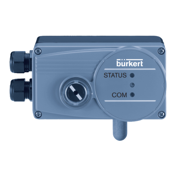
Type 8791 REV.2 Description of system DESCRIPTION OF SYSTEM Electronic module Structure Mechanical position indicator Internal position sensor Display module with 2 LEDs Pilot valve system Axle for position sensor Cable gland Working connection 2 (connection: A2) Fig. 2: Structure, positioner Type 8791 Supply pressure General description connection 1.4 – 7 bar (connection: P) The positioner Type 8791 is a digital, electro-pneumatic position controller for pneumatically actuated continuous valves. The device Working connection 1 incorporates the main function groups (connection: A1) - Position sensor - Electro-pneumatic pilot valve system Air exhaust connection/... -
Page 9: Technical Data
Type 8791 REV.2 Technical data TECHNICAL DATA Mechanical data Dimensions See data sheet Conformity Material In accordance with the EU Declaration of conformity, the posi- tioner Type 8791 is compliant with the EU Directives. H ousing material Plastic-coated aluminium Other external parts S tainless steel (V4A), PC, PE, POM, Standards PTFE The applied standards, which verify conformity with the EU Directives, can be found on the EU-Type Examination Certificate Sealing material EPDM, NBR, FKM and / or the EU Declaration of Conformity. Weight approx. 1.0 kg Operating conditions Type label WARNING! Type Operating voltage Nominal power Solar radiation and temperature fluctuations may cause mal- Device variant, communi- functions or leaks. -
Page 10: Electrical Data
Type 8791 REV.2 Technical data Electrical data 6.6.2 Electrical data, IO-Link Protection class I II as per DIN EN 61140 (VDE 0140-1) 6.6.1 Electrical data, without field bus communication Connection C ircular plug-in connector M12 x 1, 5-pin, A-coded, Port Class B Protection class I II in accordance with DIN EN 61140 (VDE 0140-1) Operating voltage System supply (Pin 1+3) 24 V DC ±25 % Connections 2 cable glands (M20 x 1.5) with screw- (according to specification) type terminals 0.14 – 1.5 mm or circular Actuator supply (Pin 2+5) 24 V DC ±25 %... -
Page 11: Pneumatic Data
Type 8791 REV.2 Operating Pneumatic data OPERATING Control medium N eutral gases, air Operating status Quality classes in accordance with ISO 8573-1 AUTOMATIC (AUTO) Dust content C lass 7, max. particle size 40 µm, max. Normal controller mode is implemented and monitored in AUTO- particle density 10 mg/m³ MATIC operating status. Water content C lass 3, max. pressure dew point -20 °C or min. 10 °C below the lowest operating MANUAL temperature In MANUAL operating status the valve can be opened and closed manually via the buttons. Oil content C lass X, max. 25 mg/m³ Temperature range 0 – +60 °C To operate the DIP switches and buttons, make sure that Pressure range 1.4 – 7 bar the local control lock is deactivated/unlocked (factory Air flow rate 5 0 l /min (at 1.4 bar... -
Page 12: Control And Display Elements Of The Positioner
Type 8791 REV.2 Operating Control and display elements of the 7.2.1 Configuration of the buttons positioner To operate the DIP switches and buttons, make sure that the local control lock is deactivated/unlocked (factory To operate the DIP switches and buttons, make sure that setting): with communication software or fieldbus the local control lock is deactivated/unlocked (factory communication. setting): with communication software or fieldbus communication. The configuration of the 2 buttons inside the housing varies depending on the operating status (AUTOMATIC / MANUAL). Button 1 The description of the operating status (AUTOMATIC / MANUAL) DIP Switches can be found in the chapter entitled “7.1 Operating status”. LED 1... - Page 13 Type 8791 REV.2 Operating MANUAL operating status (DIP switch 4 set to ON): 7.2.2 Function of the DIP switches Function Function switches Aerate (manually open / close the actuator) 1 2 3 4 Reversal of the effective direction of the set-point Deaerate (manually open / close the actuator) value (20 – 4 mA corresponds to 0 – 100 %), Longer than 10 s (< 30 s, LED 2 flashes at 5 Hz): descending (DIR.CMD) 1 and 2 Device restart Normal effective direction of the set-point value simulta- (4 – 20 mA corresponds to 0 – 100 %), ascending Longer than 30 s (LED 2 flashes at 10 Hz): neously Reset device to factory setting Sealing function active. The valve completely Tab. 1: Configuration of the keys for MANUAL operating status...
- Page 14 Type 8791 REV.2 Operating 7.2.4 Device status display Information about the communications software: The LED 1 (RGB) show the device status. The switching position of the DIP switch has priority over the communications software. The user can set the following LED modes for the display of device status and valve position. If the values of the sealing function (CUTOFF) or the • Valve mode correction characteristic (CHARACT) are changed via the communications software, the corresponding function • Valve mode with error messages must be active (DIP switch set to ON). • Valve mode with error messages and warnings (factory setting) The effective direction of the set-point value (DIR.CMD) • NAMUR mode can be changed via the DIP switches. • LED off 7.2.3 Display of the LEDs The LED mode and the colors of the valve position can be set with the Bürkert Communicator.
- Page 15 Type 8791 REV.2 Operating 7.2.5 Valve mode + warnings (factory setting) If several device statuses exist simultaneously, the device status with the highest priority is displayed. Displays in valve mode + warnings: • Valve position: open, half-way, closed Valve Device status • Device status: failure, function check, out of specification, position Out of Maintenance Failure Function maintenance required (according to NAMUR) check specifi- required cation Valve position Device status Status, Status, Status, Status, Status, color...
- Page 16 Type 8791 REV.2 Operating 7.2.7 Status LED, green If several device statuses exist simultaneously, the device status with the highest priority is displayed. The priority is determined LED 2 (green) indicates the following: by the severity of the deviation from controlled operation (red LED = failure = highest priority). Color Status Description Status display in accordance with NE 107, edition 2006-06-12 green is lit is not lit IO-Link communication inactive Color Color Status Description code flashes...
-
Page 17: Attachment And Assembly
Type 8791 REV.2 Attachment and assembly ATTACHMENT AND ASSEMBLY NAMUR lever for stroke range 35 – 130 Installation of devices for the hazardous area U-bolt When installing devices in the hazardous area, observe the Hexagon bolt DIN 933 M8 x 20 “Additional information for use in the hazardous area“ enclosed Hexagon bolt DIN 933 M8 x 16 with the Ex-devices. Circlip DIN 127 A8 Attachment to a continuous valve with linear actuators according to NAMUR Washer DIN 125 B8.4 The valve position is transferred to the position sensor installed Washer DIN 125 B6.4 in the positioner via a lever (according to NAMUR). Spring VD-115E 0.70 x 11.3 x 32.7 x 3.5... - Page 18 Type 8791 REV.2 Attachment and assembly 8.2.1 Installation → Select short or long lever according to the stroke of the actuator (see “Tab. 6: Attachment kit for linear actuators”, WARNING! part no. 6a/6b). → Assemble lever (if not pre-assembled) (see “Fig. 8”). Risk of injury from improper installation. ▶ Installation may be carried out by authorised technicians only and with the appropriate tools. Risk of injury from unintentional activation of the system and an uncontrolled restart. ▶ Secure system from unintentional activation. ▶ Following assembly, ensure a controlled restart.
- Page 19 Type 8791 REV.2 Attachment and assembly The gap between the driver pin and the axle should be Rotational range of the lever the same as the drive stroke. This results in the ideal Ideal: 60° angular range of the lever of 60° (see “Fig. 9”). Minimal: 30° Maximum: 150° Angular range of the position sensor: The maximum angular range of the position sensor is 150°. Rotational range of the lever: To ensure that the position sensor operates at a good resolution, the rotational range of the lever must be at least 30°. The rotational movement of the lever must be within the position sensor angular range of 150°. The scale printed on the lever is not relevant. The swivel movement of the lever must be within the position sensor slewing range of 150°. Fig. 9: Rotational range of the lever ⑰...
- Page 20 Type 8791 REV.2 Attachment and assembly 8.2.2 Attaching mounting bracket Attaching the positioner with mounting bracket for actuators ① with cast frame: → Attach mounting bracket to the back of the positioner with ⑨ ⑩ ⑪ → Attach mounting bracket to the cast frame with one or more hexagon bolts , circlip and washers (see “Fig. 10”). ⑧ ⑪ ⑩ hexagon bolts , washers and circlips (see “Fig.
-
Page 21: Attachment To A Continuous Valve With Rotary Actuator
Type 8791 REV.2 Attachment and assembly Attachment to a continuous valve with Attaching the positioner with mounting bracket for actuators with columnar yoke: rotary actuator → Attach mounting bracket to the columnar yoke with the U-bolt The axle of the position sensor integrated in the positioner is ⑦ ⑪ ⑩ , washers , circlips and hexagon nuts (see “Fig. connected directly to the axle of the rotary actuator. 12”). The assembly bridge can be purchased from Bürkert as an accessory by quoting the identification number 770294. - Page 22 Type 8791 REV.2 Attachment and assembly 8.3.1 Installation Angular range of the position sensor: The maximum angular range of the position sensor is WARNING! 150°. The axle of the positioner may be moved within this range only. Risk of injury from improper installation. ▶ Installation may be carried out by authorised technicians only and with the appropriate tools. Rotational range of the positioner Ideal: 90° Risk of injury from unintentional activation of the system and Minimal: 30°...
- Page 23 Type 8791 REV.2 Attachment and assembly → Assemble the multi-part assembly bridge* suitable for the → Place positioner with assembly bridge on the rotary actuator actuator. and attach (see “Fig. 15”). → Attach the assembly bridge to the positioner using 4 cheese- ③ ④ head screws and circlips . (see “Fig. 14”). ① ④ Fig. 15: Rotary actuator attachment ③ * The assembly bridge consists of 4 parts which can be adjusted to the actuator by varying the arrangement. Fig. 14: Attach assembly bridge (schematic representation) english...
-
Page 24: Remote Operation With External Position Sensor
Type 8791 REV.2 Attachment and assembly Remote operation with external 8.4.2 Connection and start-up of the Remote- Sensor Type 8798 position sensor In the case of this model the positioner has no position WARNING! sensor in the form of a rotary position sensor, but an external Remote-Sensor. Risk of injury from improper start-up. The Remote-Sensor Type 8798 is connected via a serial, digital ▶ Start-up may be carried out by authorised technicians only interface. and with the appropriate tools. Risk of injury from unintentional activation of the system and 8.4.1 Mounting accessories... -
Page 25: Fluid Connection
Type 8791 REV.2 Fluid connection FLUID CONNECTION Connection of devices for the hazardous area When connecting devices in the potentially explosive area, observe the “Additional information for use in the potentially Working connection 2 explosive area“ enclosed with the Ex-devices. (connection: A2) Safety instructions Supply pressure connection 1.4 – 7 bar (connection: P) DANGER! Working connection 1 Risk of injury from high pressure in the equipment/device. (connection: A1) ▶ Before working on equipment or device, switch off the pressure and deaerate/drain lines. Deaeration connection Fig. 17: Fluid installation / Location of the connections... -
Page 26: Safety End Positions
Type 8791 REV.2 Fluid connection Safety end positions For double-acting actuators (control function I): → Connect working connections A1 and A2 to the respective The safety end position after failure of the electrical auxiliary chambers of the double-acting actuator. power depends on the fluid connection of the actuator to the Safety end positions see chapter “9.3 Safety end positions”. working connections A1 or A2. 9.3.1 Single-acting actuators Important information for perfect control behavior. This ensures that the control behavior is not extremely Safety end positions after failure negatively affected in the upper stroke range on account of the Actuator system of too little pressure difference. - Page 27 Type 8791 REV.2 Fluid connection 9.3.2 Double-acting actuators Single-acting actuator - control function A or B Safety end positions after failure of the Actuator system electrical aux- pneumatic iliary power auxiliary power → Connection upper see “Fig. 20” chamber lower up = lower chamber chamber of the not defined actuator to A2 Connection:...
-
Page 28: Electrical Connection
Type 8791 REV.2 Electrical connection ELECTRICAL CONNECTION 10.3 Electrical connection without fieldbus communication All electrical inputs and outputs of the device are not galvanically isolated from the supply voltage. 10.3.1 Electrical connection with circular plug-in connector M12, 8-pin 10.1 Connection of devices for the hazardous area When connecting devices in the potentially explosive area, Operating voltage observe the “Additional information for use in the potentially and diverse signals explosive area“ enclosed with the Ex-devices. 10.2 Safety instructions DANGER! Risk of electric shock. - Page 29 Type 8791 REV.2 Electrical connection Pin assignment for operating voltage Pin assignment for output signals to the control centre (required for analogue output variant only) Pin Wire Configuration External circuit / Signal level Pin Wire Configuration On the External circuit / Signal...
- Page 30 Type 8791 REV.2 Electrical connection 10.3.2 Connection type 3-wire or 4-wire Connection type 3-wire The set-point value input is related to the GND line of the Setting via communication software supply voltage, i.e. setpoint input and supply voltage have a common GND line. Connection type 4-wire (factory setting) The set-point value input is designed as a differential input, i.e. the GND lines of the set-point value input and the supply 0/4 – 20 mA voltage are not identical. Note: If the GND signals of the set-point value input and the supply voltage are connected, the 3-wire connection type must be set in the software. +24 V DC 0/4 – 20 mA Tab. 14: Connection type 3-wire +24 V DC Tab. 13: Connection type 4-wire...
- Page 31 Type 8791 REV.2 Electrical connection Terminal assignment for input signals from the control centre 10.3.3 Electrical connection with cable gland (e.g. PLC) 11 + Terminal Configuration On the External circuit / Signal 12 – device side level 11 + Set-point 11 + + (0/4 – 20 mA)
- Page 32 Type 8791 REV.2 Electrical connection 10.3.5 Terminal assignment for connecting the Terminal assignment for output signals to the control centre (required for analogue output variant only) external position sensor (for remote model only) Terminal Configuration On the External circuit / Signal...
-
Page 33: 10.4 Electrical Installation, Io-Link
Type 8791 REV.2 Electrical connection 10.4 Electrical installation, IO-Link 10.5 Electrical installation, büS Fig. 24: Pin assignment Fig. 23: Pin assignment, Port Class B Wire color Configuration CAN plate/shielding CAN plate/shielding Designation Configuration +24 V DC ±25 %, max. residual ripple 10 % 24 V DC System supply black GND / CAN_GND 24 V DC Actuator supply white CAN_H L –... -
Page 34: Start-Up
Type 8791 REV.2 Start-up START-UP 11.2.1 Running the automatic adjustment X.TUNE: 11.1 Safety instructions WARNING! WARNING! Danger due to the valve position changing when the X.TUNE function is running. Risk of injury from improper operation. When the X.TUNE is running under operating pressure, there is Improper operation may result in injuries as well as damage to an acute risk of injury. the device and the area around it. ▶ Never run X.TUNE while a process is running. -
Page 35: Setting With Bürkert Communicator
Type 8791 REV.2 Start-up → To connect the IO-Link device to the Bürkert Communicator, → Start X.TUNE by pressing button 1 for 5 sec unscrew the housing cover. LED 2 flashes at 5 Hz. The device is in the NAMUR state function → Insert micro USB plug in büS service interface. check, LED 1 lights orange. → Establish connection to PC with büS stick. If the X.TUNE is successfully completed, the NAMUR state is reset → Starting Bürkert Communicator. again. The changes are automatically transferred to the memory → Implementing settings. (EEPROM) provided the X.TUNE function is successful. Button 1 DIP Switches When LED 1 lights red after X.TUNE: LED 1 → Execute X.TUNE again. LED 2 → Perform a device restart if necessary. 14) The X.TUNE can also be started via communications software. -
Page 36: Io-Link
Type 8791 REV.2 Start-up 11.4 IO-Link Min. cycle time 5 ms Data storage 11.4.1 Information, IO-Link Max. cable length 20 m IO-Link is an internationally standardized IO technology (IEC 61131-9) to enable sensors and actuators to communicate. IO-Link is a point-to-point communication with 3-wire connection 11.4.3 Configuration of the fieldbus technology for sensors and actuators and unshielded standard The required start-up files and the description of the process sensor cables. data and acyclic parameters are available on the Internet. To ensure clear communication, the IO-Link devices should not Download from: be parameterised simultaneously by the higher-level controller www.burkert.com / Type 8791 / Software (PLC) via the IO-Link master and with the Bürkert Communicator (via the service interface). 11.5 büS 11.4.2 Technical specifications, IO-Link 11.5.1 Information, büS IO-Link specifications V1.1.2... -
Page 37: Accessories
Type 8791 REV.2 Accessories 12.1 Communications software ACCESSORIES The PC operating program “Communicator” is designed for com- Designation Order no. munication with the devices from the Bürkert positioner family. Connection cable M12 x 1, 8-pin 919061 If you have any questions regarding compatibility, please contact the Bürkert Sales Center. Communication software Bürkert Information at Communicator www.burkert.com A detailed description and precise schedule of the pro- Tab. 22: Accessories cedure for the installation and operation of the software can be found in the associated documentation. -
Page 38: Packaging, Transport, Storage
Type 8791 REV.2 Packaging, transport, storage PACKAGING, TRANSPORT, STORAGE NOTE! Transport damages. Inadequately protected equipment may be damaged during transport. ▶ During transportation protect the device against moisture and dirt in shock-resistant packaging. ▶ Follow the allowable storage temperature. Incorrect storage may damage the device. ▶ Store the device in a dry and dust-free location. ▶ Storage temperature -20 – +65 °C. Damage to the environment caused by device components contaminated with media. - Page 40 www.burkert.com...
Need help?
Do you have a question about the 8791 REV.2 and is the answer not in the manual?
Questions and answers