Burkert SideControl 8635 Operating Instructions Manual
Electropneumatic positioner
Hide thumbs
Also See for SideControl 8635:
- Operating instructions manual (190 pages) ,
- Additional instructions (22 pages) ,
- Operating instructions manual (166 pages)
Table of Contents
Advertisement
Quick Links
Advertisement
Table of Contents

Related Manuals for Burkert SideControl 8635


Summary of Contents for Burkert SideControl 8635
- Page 1 Type 8635 SideControl Electropneumatic positioner Operating Instructions...
- Page 2 We reserve the right to make technical changes without notice. © Bürkert Werke GmbH & Co. KG, 2003-2020 Operating Instructions 2002/07_EN-en_00804608 / Original DE...
-
Page 3: Table Of Contents
Contents Operating instructiOns ........................6 Symbols ............................6 1.2 Definition of terms .........................6 intended use ............................7 Basic safety instructiOns ......................8 general nOtes...........................9 Contact addresses ........................9 Warranty ............................9 Master code ..........................9 4.4 Information on the Internet ......................9 prOduct descriptiOn ........................10 Product variants ..........................11 Options ............................12 Functional diagram ........................13 5.4 Interfaces ............................14 Operation as positioner .......................15... - Page 4 Type 8635 electrical cOnnectiOn ........................39 Operating and display elements .....................41 13.1 Assignment of the keys .......................41 Operating levels ..........................42 Operating states ..........................43 15.1 Changing the operating state ......................43 15.2 Detecting the operating state ......................43 autOmatic Operating state during pOsitiOn cOntrOl .............44 16.1 Meaning of the keys ........................44 16.2 Displays in AUTOMATIC operating state: ...................44 autOmatic Operating state during prOcess cOntrOl .............45 17.1 Meaning of the keys ........................45 17.2 Displays in AUTOMATIC operating state: ...................45 Basic functiOns and auxiliary functiOns ................47...
- Page 5 Type 8635 start-up as pOsitiOner .........................77 20.1 Carry out the X.TUNE function (AUTOTUNE) ................78 20.2 X.TUNE function - manual TUNE ....................80 start-up as prOcess cOntrOller ....................82 21.1 Sequence of the work steps .......................82 21.2 P.TUNE: Carrying out self-optimisation of the process controller ..........83 21.3 Manual changing of the process set-point value ................86 maintenance and trOuBleshOOting ..................87 22.1 Maintenance ..........................87 22.2 Error messages, position control ....................87 22.3 Error messages, process control ....................89 accessOries .............................90 packaging, transpOrt ........................91 stOrage .............................91...
-
Page 6: Operating Instructions
Type 8635 Operating instructions OperaTing insTrucTiOns The operating instructions describe the entire life cycle of the device. Keep these instructions in a location which is easily accessible to every user and make them available to every new owner of the device. important safety information! Carefully read through the operating instructions. In particular, pay attention to section “Intended use” and “Basic safety instructions”. ▶ The operating instructions must be read and understood. symbols Danger warns of an immediate danger. ▶ Failure to observe will result in death or serious injuries. Warning warns of a potentially hazardous situation. ▶ Failure to observe these instructions may result in serious injuries or death. Caution warns of a potential danger. ▶... -
Page 7: Intended Use
Type 8635 Intended use inTended use The SideControl Type 8635 has been designed for the position control of pneumatically actuated control valves with single-acting linear actuators or with single-acting rotary actuators. ▶ In potentially explosive atmospheres, only use devices that are approved for this purpose. These devices are marked with the ATEX logo on the type label. For use, observe the information on the type label and the additional instructions enclosed with the device, marked with the ATEX logo. ▶ Do not use devices without the ATEX logo on the type label in potentially explosive atmospheres. ▶ Do not expose the device to direct sunlight. ▶ To achieve a degree of protection of IP65, seal the cable entries tightly. ▶ Use the device only in its original condition and when it is in perfect working order. ▶ Use the device only in conjunction with third-party devices and components recommended or approved by Bürkert. ▶ Use the device only as intended. Non-intended use of the device may be dangerous to people, nearby equipment and the environment. ▶ Prerequisites for safe and trouble-free operation are correct transportation, correct storage, installation, start-up, operation and maintenance. ▶ To use the device, observe the permitted data, operating conditions and application conditions. These specifications can be found in the contract documents, the operating instructions and on the type label. English... -
Page 8: Basic Safety Instructions
Type 8635 Basic safety instructions Basic safeTy insTrucTiOns These safety instructions do not take into account any unforeseen circumstances and events which occur during installation, operation and maintenance. The operator is responsible for observing the location-specific safety regulations, also with reference to the personnel. risk of injury due to high pressure and escaping medium. ▶ Before working on the device or system, switch off the pressure. Exhaust or empty the lines. risk of injury due to electric shock. ▶ Before working on the device or system, switch off the power supply. Secure against reactivation. ▶ Observe the applicable accident prevention and safety regulations for electrical devices. general hazardous situations. To prevent injuries, observe the following: ▶... -
Page 9: General Notes
Type 8635 General notes general nOTes Contact addresses germany Bürkert Fluid Control Systems Sales Centre Christian-Bürkert-Str. 13-17 D-74653 Ingelfingen Tel. + 49 (0) 7940 - 10 91 111 49 Fax + 0 (7940) 10 91 448 - 10-91 448 Email: info@burkert.com international The contact addresses can be found on the back pages of the printed Quickstart. The printed Quickstart is included in the scope of delivery of the device. You can also find the contact addresses on the Internet at: www.burkert.com Warranty A precondition for the warranty is that the device is used as intended in consideration of the specified oper- ating conditions. Master code Operation of the device can be locked via a freely selectable 4-digit code. Regardless of this, there is an unchangeable master code with which you can perform all operating actions on the device. This 4-digit master code can be found on the back pages of the printed Quickstart. The printed Quickstart is included in the scope of delivery of the device. If necessary, cut out the code and keep it separately from the operating instructions. Information on the Internet Operating instructions and data sheets for the Bürkert products can be found on the Internet at: www.burkert.com English... -
Page 10: Product Description
Type 8635 Product description prOducT descripTiOn The SideControl Type 8635 is an electropneumatic positioner for pneumatically actuated control valves with single-acting stroke or rotary actuators. The device controls the valve position according to the set-point position. The set-point position is specified by an external standard signal. If equipped with a PID controller (optional), Type 8635 can be used as a process controller. Display and operating element Connection terminals Throttle screw Earthing screw Cable glands M 20 x 1.5 Figure 1: Structure of the SideControl Type 8635 English... -
Page 11: Product Variants
Type 8635 Product description Product variants The SideControl Type 8635 is available in different variants depending on the actuator type of the control valve to be controlled. 5.1.1 Direct attachment to Bürkert control valves Type 27xx For Bürkert control valves with external air routing, actuator sizes ∅ 175 + 225 mm. With pre-assembled cable (0.3 m) for connection to position sensor Type 8635. In this variant, the SideControl Type 8635 is only supplied as part of a complete control system (SideControl + position sensor + associated attachments + control valve). 5.1.2 Remote variant for Bürkert control valves Type 23xx Working port 2 Mounting bracket Connection cable (depicted shorter) -
Page 12: Options
Type 8635 Product description 5.1.3 Direct attachment to rotary actuators or linear actuators For attachment to external actuators according to NAMUR/IEC. With integrated position sensor. Options 5.2.1 Integrated process controller Using a process controller with PID behaviour, it is possible to set up a decentralised closed-loop control. In addition to the valve position, measured variables such as level, pressure, flow or temperature can be controlled. The actual values of the measured variables to be controlled are determined via an integrated or external position sensor and via connected sensors, compared with the specified set-point values and cor- rected, if necessary. 5.2.2 Analogue feedback Values such as actual position or process actual value can be output to the controller via the analogue feedback. 5.2.3 2 digital outputs Various controller states can be output via the digital outputs. The setting options are described in detail in section “19.15 OUTPUT: Configuring outputs (option)” on page 72. The digital outputs behave like a NAMUR sensor acc. to EN 60947-5-6. 5.2.4 ATEX approval EEx ia II C T6 In potentially explosive atmospheres, only use devices that are approved for this purpose. -
Page 13: Functional Diagram
Type 8635 Product description Functional diagram Functional diagram of the SideControl Type 8635 in conjunction with a control valve with a single-acting actuator. The grey areas show the additional functions when the device is used as a process controller (option). Compressed control valve with air supply single-acting actuator sidecontrol type 8635 External set-point position Microprocessor- controlled electronics Actual position external process Actuating Set-point position system* set-point Exhaust value process Position controller sensor process actual value... -
Page 14: Interfaces
Type 8635 Product description Interfaces Digital input 2 digital outputs Set-point position Analogue or process set-point feedback sidecontrol value 4...20 mA 4...20 mA type 8635 Process actual value 4...20 mA (for process controller option only) Operation Remark: Optional inputs and outputs are shown with a dashed line Figure 3: Interfaces of the positioner / process controller The SideControl Type 8635 is a 2-wire device, i.e. power supply takes place via the set-point signal. -
Page 15: Operation As Positioner
Type 8635 Product description Operation as positioner The position sensor records the current position (POS, actual position) of the pneumatic actuator. The posi- tioner compares this actual position with the set-point position (CMD) specified as a standard signal. If there is a control difference (Xd1), the positioner sends a pulse width modulated voltage signal to the actuating system as an actuating variable. With single-acting actuators, the pressurising valve is actuated via output B1 if there is a positive control difference. If the control difference is negative, the exhausting valve is actuated via output E1. In this way, the position of the actuator is changed up to control difference 0. Z1 is a disturbance. Valve opening – Positioner Actuating system Control External (piezoelectric valve set-point valves) position Actual position (POS) Position sensor Position control loop Figure 4: Presentation of the position control loop... -
Page 16: Operation As A Process Controller (Option)
Type 8635 Product description Operation as a process controller (option) If the SideControl Type 8635 is operated as a process controller, the position control becomes a subor- dinate auxiliary control loop. This results in cascade control. The process controller (as the main control loop) is implemented in the device as a PID controller. In this case, the process set-point value (SP) is specified as the set-point value and compared with the process actual value (PV). The process actual value is supplied by a sensor. The actuating variable is formed according to the description of the positioner. Z2 represents a disturbance acting on the process. Valve opening Actuating system Control Positioner solenoid valves valve Position control Position sensor loop Valve Measured variable Position opening control loop Process Process Process controller set-point... - Page 17 Type 8635 Product description – DIR.ACT X.LIMIT X.CONTRL DBDx DIR.CMD SPLTRNG CHARACT CUTOFF X.TIME P.CO SCAL P.CO FILT – P.CONTRL 4...20 mA DBDp P.CO SCAL PARA TUNE Figure 7: Schematic presentation of the process control English...
-
Page 18: Technical Data
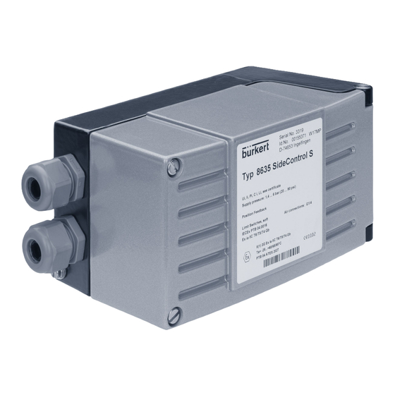
Type 8635 Technical data Technical daTa Conformity The device conforms to the EU directives as per the EU Declaration of Conformity (if applicable). Standards The applied standards, which are used to demonstrate conformity with EU directives, are listed in the EU type examination certificate and/or the EU Declaration of Conformity (if applicable). Type label Serial no. 1001 ID no. 00123456 W19UU Made in Germany SideControl S type 8635 Device with Permitted pressure range supply pressure: 1.4...6 bar (20...90 psi) ”analogue feedback” option Device with “process position feedback process control... -
Page 19: Operating Conditions
Type 8635 Technical data Operating conditions Warning Sunlight or temperature fluctuations may cause malfunctions or leaks. ▶ When used outdoors, protect the device against adverse weather conditions. ▶ Do not exceed or undercut the permissible ambient temperature. Permitted ambient temperature –25...+65 °C (for temperature class T4/T5 or for devices without EEx-ia approval) –25...+60 °C (for temperature class T6) At temperatures below 0 °C, the display may show an extended response time and reduced contrast. Degree of protection IP65 acc. to EN 60529 (to achieve a degree of protection of IP65, seal the cable entries tightly) 6.4.1 Fluidic data Control medium Neutral gases, air quality classes acc. to DIN ISO 8573-1... - Page 20 Type 8635 Technical data 6.4.2 Electrical data Protection class III acc. to DIN EN 61140 Connection 2 cable glands (M 20 x 1,5), connection terminals 0.14...1.5 mm Power supply Via set-point value input 4...20 mA, 2-wire technology Load voltage < 10.2 V Load resistance 590 Ω (at 20 mA and 11.8 V Process actual value input 4...20 mA (optional) Load voltage 200 mV at 20 mA Load resistance 10 Ω...
-
Page 21: Safety End Positions After Failure Of The Electrical Or Pneumatic Auxiliary Power
Type 8635 Technical data 6.4.3 Mechanical data Dimensions see data sheet Materials Housing Aluminium, hard anodised and plastic coated Cable glands PA + NBR (seals) Other external parts Stainless steel V4A Seal material NBR (O-rings) CE Neoprene (sponge rubber round cord) Weight Approx. 1.5 kg Safety end positions after failure of the electrical or pneumatic auxiliary power Safety end positions after failure of the Actuator type Designation electrical auxiliary power pneumatic auxiliary power... -
Page 22: Direct Attachment To Bürkert Control Valves
Type 8635 Direct attachment to Bürkert control valves direcT aTTachmenT TO BürkerT cOnTrOl valves This variant of the SideControl Type 8635 is only supplied as part of a complete control system (SideControl + position sensor + associated attachments + control valve). The control system is already fully assembled and tested upon delivery. English... -
Page 23: Installation Of The Remote Variant
Type 8635 Installation of the Remote variant insTallaTiOn Of The remOTe varianT Danger risk of injury due to high pressure and escaping medium. ▶ Before working on the device or system, switch off the pressure. Exhaust or empty the lines. risk due to electric shock. ▶ Before working on the device or system, switch off the power supply. Secure against reactivation. Warning risk of injury due to improper installation. ▶... -
Page 24: Wall Mounting With Mounting Bracket
Type 8635 Installation of the Remote variant Wall mounting with mounting bracket The SideControl Type 8635 Remote variant is supplied with a pre-assembled mounting bracket. The mounting bracket can be used for mounting the device on a wall. 26.2 Figure 9: Dimensions of the pre-assembled mounting bracket English... -
Page 25: Position Sensor Remote" Attachment Kit
Type 8635 Installation of the Remote variant “Position sensor Remote” attachment kit The Remote variant does not have a position sensor in the form of a rotary position sensor. The device is connected to an external position sensor. With this variant, the connection cable for connecting the device to the position sensor is pre-assembled. To be able to mount the position sensor on the actuator of the control valve, the attachment kit, which is available as an accessory, must first be mounted on the actuator (see section “23 Accessories” on page 90). Switch spindle Switch cam Lip seal Switch spindle Guide element Form seal Guide element Form seal Figure 10: “Position sensor Remote” attachment kit Actuator with mounted attachment kit preparing the control valve: →... -
Page 26: Mounting The Position Sensor On The Actuator
Type 8635 Installation of the Remote variant Mounting the position sensor on the actuator: Slide Potentiometer Switch cam Casing Basic housing Fastening screw (x2) Figure 11: Position sensor Remote → Unscrew the casing of the position sensor counterclockwise and remove it. → In the basic housing of the position sensor, push the slide of the potentiometer downwards. → Ease the basic housing over the switch cam of the valve actuator, while inserting the slide of the potenti- ometer laterally into the switch cam. → Align the connection piece of the basic housing with the pilot air ports of the valve actuator (see “Figure 12”). note! ▶... -
Page 27: Connecting The Position Sensor Electrically
Type 8635 Installation of the Remote variant Connecting the position sensor electrically Danger! risk due to electric shock. ▶ Before working on the device or system, switch off the power supply. Secure against reactivation. 3-pole flat connector Cable gland of the position sensor Figure 13: Electrical connection → Feed the cable pre-assembled on the SideControl Type 8635 with the mounted flat connector through the cable gland of the position sensor. → Connect the flat connector to its counterpart in the position sensor. → When tightening the cable gland, pay attention to the position of the plug connection. See marked area in the following “Figure 14”. -
Page 28: Connecting The Position Sensor Pneumatically
Type 8635 Installation of the Remote variant Connecting the position sensor pneumatically Danger! risk of injury due to high pressure and escaping medium. ▶ Before working on the device or system, switch off the pressure. Exhaust or empty the lines. adjust the length of the pilot air line to the actuator size. The dead space volume created by the pilot air line can have a negative impact on the control characteristics. Basically, the smaller the actuator, the more sensitive the control system reacts to the length of the pilot air line. -
Page 29: Direct Attachment Of The Linear Actuator
Type 8635 Direct attachment of the linear actuator direcT aTTachmenT Of The linear acTuaTOr Danger risk of injury due to high pressure and escaping medium. ▶ Before working on the device or system, switch off the pressure. Exhaust or empty the lines. risk due to electric shock. ▶ Before working on the device or system, switch off the power supply and secure to prevent reactivation. Warning risk of injury due to improper installation. ▶... -
Page 30: Attachment Kit For Linear Actuators
Type 8635 Direct attachment of the linear actuator Attachment kit for linear actuators An attachment kit is required to mount the SideControl on linear actuators according to NAMUR. The attachment kit is available as an accessory from Bürkert (see section “23 Accessories”). seq. Quantity designation [pieces] NAMUR mounting bracket IEC 534 Hoop Clamping piece Driver pin Conical roller NAMUR lever for stroke range 3...35 mm NAMUR lever for stroke range 35...130 mm U-bolt Hexagon bolt DIN 933 M8 x 20 Hexagon bolt DIN 933 M8 x 16 Spring lock washer DIN 127 A8 Washer DIN 125 B8.4 Washer DIN 125 B6.4 Spring VD-115E 0.70 x 11.3 x 32.7 x 3.5 Spring washer DIN 137 A6 Locking washer DIN 6799 - 3.2 Spring lock washer DIN 127 A6 Hexagon bolt DIN 933 M6 x 25 Hexagon nut DIN 934 M6 Square nut DIN 557 M6... -
Page 31: Mounting The Hoop And Lever
Type 8635 Direct attachment of the linear actuator Mounting the hoop and lever The valve position is transmitted to the position sensor installed in the SideControl Type 8635 via a lever (according to NAMUR). Legend: designation Hoop Clamping piece Spring lock washer Hexagon bolt Figure 16: Mounting the hoop → Mount the hoop ② on the actuator spindle using the clamping pieces ③, the hexagon bolts ⑰ and the spring lock washers ⑯. → Select the short lever or the long lever according to the stroke of the actuator. → Assemble the lever, if not pre-assembled (see “Figure 17”). Legend: designation Driver pin Conical roller Lever Washer... -
Page 32: Attaching The Mounting Bracket
Type 8635 Direct attachment of the linear actuator The gap between the driver pin and the shaft should be the same as the actuator stroke. As a result, the lever has an ideal rotational range of 60°. This ensures that the position sensor operates at a good resolution. angular range of the position sensor: The maximum angular range of the position sensor is 120°. rotational range of the lever: Minimum 30° Ideal 60° Maximum 120° (within the angular range of the position sensor) The scale printed on the lever is not relevant. Gap = stroke of the actuator Figure 18: Rotational range of the lever →... - Page 33 Type 8635 Direct attachment of the linear actuator Legend: designation Mounting bracket Conical roller Lever Hexagon bolt Spring lock washer Washer Figure 19: Attaching the mounting bracket to the SideControl Type 8635 for actuators with a cast frame: → Attach the mounting bracket to the cast frame using one or more hexagon bolts ⑧, the washers ⑪ and the spring lock washers ⑩ (see “Figure 20”). Legend: designation Mounting bracket...
-
Page 34: Aligning The Lever Mechanism
Type 8635 Direct attachment of the linear actuator Aligning the lever mechanism The lever mechanism cannot be correctly aligned until the device has been electrically and pneumati- cally connected. → Move the actuator in MANUAL operating state to half stroke (according to the scale on the actuator). → Adjust the height of the SideControl Type 8635 until the lever is horizontal. → Fix the SideControl Type 8635 in this position on the actuator. English... -
Page 35: Direct Attachment To The Rotary Actuator
Type 8635 Direct attachment to the rotary actuator direcT aTTachmenT TO The rOTary acTuaTOr Danger risk of injury due to high pressure and escaping medium. ▶ Before working on the device or system, switch off the pressure. Exhaust or empty the lines. risk due to electric shock. ▶ Before working on the device or system, switch off the power supply. Secure against reactivation. Warning risk of injury due to improper installation. ▶... -
Page 36: Mounting The Sidecontrol On The Rotary Actuator
Type 8635 Direct attachment to the rotary actuator 10.2 Mounting the SideControl on the rotary actuator The shaft of the position sensor integrated in the SideControl Type 8635 is connected to the shaft of the rotary actuator using the adapter. prior to mounting → Specify the attachment position of the SideControl Type 8635: - parallel to the actuator or - rotated by 90° to the actuator → Determine the home position and the direction of rotation of the actuator. → Align the flat side of the shaft to the rotational range (see “Figure 22”). The maximum rotational range is 120°. installation → Connect the adapter ① to the shaft of the SideControl and attach it using the two setscrews ② and the hexagon nuts ⑤ . anti-twist safeguard: One of the setscrews must be situated on the flat side of the shaft. → Assemble the assembly bridge suitable for the actuator. The assembly bridge consists of 4 parts, which can be adjusted to the actuator by varying the arrangement. - Page 37 Type 8635 Direct attachment to the rotary actuator ① ②+⑤ ④ ③ ⑥ Figure 23: Attaching the assembly bridge Figure 24: Mounting the SideControl on the rotary actuator English...
-
Page 38: Pneumatic Connection
Type 8635 Pneumatic connection pneumaTic cOnnecTiOn Danger risk of injury due to high pressure and escaping medium. ▶ Before working on the device or system, switch off the pressure. Exhaust or empty the lines. Warning risk of injury due to improper installation. ▶ Installation may be carried out by authorised technicians only and with the appropriate tools. risk of injury due to unintentional activation of the system and uncontrolled restart. ▶... -
Page 39: Electrical Connection
Type 8635 Electrical connection elecTrical cOnnecTiOn Danger risk of injury due to electric shock. ▶ Before working on the device or system, switch off the power supply. Secure against reactivation. ▶ Observe the applicable accident prevention and safety regulations for electrical devices. Warning risk of injury due to improper installation. ▶ Installation may be carried out by authorised technicians only and with the appropriate tools. risk of injury due to unintentional activation of the system and uncontrolled restart. ▶... - Page 40 Type 8635 Electrical connection Figure 26: SideControl Type 8635 connection terminals description assignment external circuit of terminal 11 + Set-point value + 4...20 mA standard signal 12 – Set-point value – 13 + Process actual value + (option) 4...20 mA standard signal 14 – Process actual value – (option) Actual value output + (option) 12...30 V –...
-
Page 41: Operating And Display Elements
Type 8635 Operating and display elements OperaTing and display elemenTs The positioner is parameterised and operated via a display with plain text display and 3 operation keys. The operating elements are located under the housing lid. Process values such as set-point value and actual value are also shown on the display. Arrow keys MANUAL/AUTOMATIC key 13.1 Assignment of the keys at process level: Toggling between the MANUAL and AUTOMATIC operating states MANUAL/AUTOMATIC key at setting level: Toggling between the main menu and the additional menu Toggling between equal menu options, Arrow keys e.g. ADDFUNCT - X.TUNE English... -
Page 42: Operating Levels
Type 8635 Operating levels OperaTing levels Operating level description Process level The process level is active after switching on the device. At this level, it is toggled between the MANUAL and AUTOMATIC operating states. Setting level This level contains the main menu with the basic functions. Auxiliary func- tions can be enabled via the ADDFUNCT basic function. If auxiliary func- tions are enabled, they appear in the main menu and can be configured there. A firmly established basic function is the X.TUNE function. When exe- cuting this basic function, the SideControl Type 8635 automatically deter- mines the optimum settings for the valve used and the current operating conditions (supply pressure). At setting level, the control valve remains in the last controlled position. Table 5: Operating levels of the software process level setting level Main menu ADDFUNCT Additional menu MANUAL... -
Page 43: Operating States
Type 8635 Operating states OperaTing sTaTes Operating state description MANUAL Manual opening or closing of the control valve. AUTOMATIC Executing and monitoring automatic position control (or process control with process controller option). 15.1 Changing the operating state Changing between MANUAL and AUTOMATIC operating state. Only possible at process level. press briefly In both MANUAL and AUTOMATIC operating state: Change to setting level. press for 5 s 15.2 Detecting the operating state Operating state display AUTOMATIC An apostrophe (') runs continuously from left to right. -
Page 44: Automatic Operating State During Position Control
Type 8635 AUTOMATIC operating state during position control auTOmaTic OperaTing sTaTe during pOsiTiOn cOnTrOl Normal controlled operation is executed and monitored in AUTOMATIC operating state. 16.1 Meaning of the keys Toggling the display Changing the set-point position (with configured P.CONTRL / P.CO SETP / SETP INT auxiliary function and set > 3 s display SP) 16.2 Displays in AUTOMATIC operating state: By pressing the arrow keys you can toggle between 3 display variants. -
Page 45: Automatic Operating State During Process Control
Type 8635 AUTOMATIC operating state during process control auTOmaTic OperaTing sTaTe during prOcess cOnTrOl Normal controlled operation is executed and monitored in AUTOMATIC operating state. 17.1 Meaning of the keys Toggling the display Changing the process set-point value (with configured P.CONTRL / P.CO SETP / SETP INT auxiliary function and set display SP) > 3 s making P.TUNE (process tune) ready to start (with PID self-optimisation enabled) P.CONTRL / P.CO TUNE / P.TUN ACT 17.2 Displays in AUTOMATIC operating state: By pressing the arrow keys you can toggle between 4 display variants. - Page 46 Type 8635 AUTOMATIC operating state during process control If the device is in the safety position (for the corresponding configuration, see “19.13 SIG-ERR Con- figuring the signal error detection” on page 70 or “19.14 BIN-IN: Setting the function of the digital input” on page 71), SAFE XXX appears on the display. If the CUTOFF auxiliary function has been enabled and the process valve is in the sealing area, a flashing MIN or MAX symbol appears on the display. If the measuring range of the process actual value is exceeded or undercut, a flashing bar appears on the display. English...
-
Page 47: Basic Functions And Auxiliary Functions
Type 8635 Basic functions and auxiliary functions Basic funcTiOns and auxiliary funcTiOns The operating concept for the SideControl Type 8635 is based on a strict separation between basic func- tions and auxiliary functions. Only the basic functions are enabled when the device is delivered. They are sufficient for normal operation. Auxiliary functions can be enabled for more demanding control tasks. If auxiliary functions are enabled, they become part of the main menu and can be parameterised there. 18.1 Main menu with the basic functions function/menu description ADDFUNCT Contains the auxiliary functions. The auxiliary functions are enabled or disabled in this menu. The auxiliary functions can be accessed by pressing the MANUAL/AUTOMATIC key. X.TUNE AUTOTUNE or manual TUNE This function adjusts the position control to the physical stroke of the control valve. Completing the configuration, returning to process level. Table 6: Basic functions of the SideControl Type 8635 18.2 Function of the keys in the main menu and addfuncT... -
Page 48: Auxiliary Functions That Can Be Enabled
Type 8635 Basic functions and auxiliary functions 18.3 Auxiliary functions that can be enabled The functions shown in grey are valid for the “Process controller” option (P.xxx) or for the “Analogue feedback” option (OUTPUT). function description CHARACT Selecting the characteristic type CUTOFF Enabling and configuring the sealing function DIR.CMD Setting the effective direction of the input signal for the set-point value to position the valve actuator DIR.ACT Setting the effective direction of the pressurisation state of the valve actuator to the actual position SPLTRNG Splitting the standard signal range between several devices Not available for process controller option! X.LIMIT Limiting the mechanical stroke range X.TIME Reducing the control speed X.CONTRL Parameterising the position control CODE Enabling and configuring the code protection SAFEPOS Setting the safety position... -
Page 49: Factory Settings Of The Auxiliary Functions
Type 8635 Basic functions and auxiliary functions 18.4 Factory settings of the auxiliary functions The functions and factory settings shown in grey are valid for the “Process controller” option (P.xxx) or for the “Analogue feedback” option (OUTPUT). function factory setting CHARACT CHA LIN CUTOFF CUT = 0%; CUT = 100% DIR.CMD DIR.CRISE DIR.ACT DIR.ARISE SPLTRNG SR = 0 (%); SR = 100 (%) X.LIMIT LIM = 0%;... -
Page 50: Enabling And Disabling Auxiliary Functions
Type 8635 Basic functions and auxiliary functions 18.5 Enabling and disabling auxiliary functions The configuration menu consists of the main menu and the additional menu. The main menu initially contains the basic functions that are specified during initial start-up. The additional menu comprises supplementary functions and can be accessed via the menu optionADDFUNCT in the main menu. Device functions and device parameters can be specified within the main menu. If required, the main menu can be extended by functions from the additional menu, which can then be specified. main menu additional menu Confirm the selected menu option ADDFUNCT CHARACT Select the X.TUNE *CUTOFF menu option ADDFUNCT DIR.CMD DIR.ACT SPLTRNG X.LIMIT Select the X.TIME menu option *X.CONTRL... -
Page 51: Setting Numerical Values
Type 8635 Basic functions and auxiliary functions 18.6 Setting numerical values Numerical values are set in the menu options provided for this purpose by pressing the arrow keys once or several times. With four-digit numbers, only the flashing position can be set with the arrow keys. Pressing the MANUAL/AUTOMATIC key advances to the next position. function Incrementing (increasing) numerical values Decrementing (reducing) numerical values With multi-digit numbers, advancing to the next position English... -
Page 52: Overview Of The Auxiliary Functions
Type 8635 Basic functions and auxiliary functions 18.7 Overview of the auxiliary functions In order to be able to edit auxiliary functions, they must first be included in the main menu (see section “18.5” on page 50). Removing a function from the main menu invalidates the settings previously made under that function. “19.1 CHARACT: Selecting the characteristic type” ADDFUNCT CHARACT “19.2 CUTOFF: Sealing function” CUTOFF “19.3 DIR.CMD: Effective direction of the set-point DIR.CMD value for setting the valve position” “19.4 DIR.ACT: Setting the effective direction of the pressuri- DIR.ACT sation state of the actuator to the actual position” “19.5 SPLTRNG: Splitting the standard signal range” SPLTRNG “19.6 X.LIMIT: Limiting the mechanical stroke range” X.LIMIT “19.7 X.TIME: Reducing the control speed” X.TIME “19.8 X.CONTRL Parameterising the position control” X.CONTRL “19.9 P.CONTRL: Parameterising the process control”... -
Page 53: Description Of The Auxiliary Functions
Type 8635 Description of the auxiliary functions descripTiOn Of The auxiliary funcTiOns In order to be able to edit auxiliary functions, they must first be included in the main menu (see section “18.5” on page 50). Removing a function from the main menu invalidates the settings previously made under that function. 19.1 CHARACT: Selecting the characteristic type This function is used to select the correction characteristic which is used to correct the flow characteristic and the operating characteristic in relation to the set-point position (CMD) and the valve stroke (POS). factory setting: Characteristic correction disabled, linear characteristic (CHA LIN) Linear characteristic CHARACT CHA LIN Equipercentile characteristic 1:25 CHA 1/25 Equipercentile characteristic 1:33 CHA 1/33 Equipercentile characteristic 1:50 CHA 1/50 Inverse equipercentile characteristic 25:1... - Page 54 Type 8635 Description of the auxiliary functions Operating characteristic: The operating characteristic Q = f(s) shows the relationship between the volume flow Q in the installed valve and the stroke s. The properties of the pipelines, pumps and consumers are included in this characteristic. The operating characteristic therefore has a different shape than the flow characteristic. For positioning applications of controllers, special requirements are often placed on the operating charac- teristic, e.g. linearity. For this reason, it is necessary to correct the operating characteristic in an appropriate manner. A transmission element is therefore provided in the device, which ensures various characteristics. These characteristics are used to correct the operating characteristic. Equipercentile characteristics 1:25, 1:33, 1:50, 25:1, 33:1 and 50:1 as well as a linear characteristic can be set. In addition, it is possible to program a user-defined characteristic by entering supporting points. Standardised valve stroke [%] (POS) Set-point position [%] Figure 30: Characteristic correction (CHARACT) English...
- Page 55 Type 8635 Description of the auxiliary functions 19.1.1 Programming user-defined characteristics The characteristic is defined via 21 supporting points in 5% increments, which are evenly distributed over the set-point range from 0...100%. A freely selectable stroke (setting range 0...100%) can be assigned to each supporting point. The difference between the stroke values of two adjacent supporting points must not be greater than 20%. recommendation: Make a note of the entered supporting points in the table in the appendix. Supporting point (%) Function value (%) Set function value CHARACT CHA FREE 0 XXX Set function value 5 XXX Set function value 10 XXX Set function value 95 XXX 100 XXX Figure 31: Operating structure CHA FREE Valve stroke [%] Set-point value [%] 4...20 mA...
-
Page 56: Cutoff: Sealing Function
Type 8635 Description of the auxiliary functions 19.2 CUTOFF: Sealing function This function causes the valve to seal tightly or to open fully within an adjustable range. The limits for the set-point position (CMD) above which the actuator is fully exhausted or pressurised are set in percent. The transition from the set range to normal operation takes place with a hysteresis of 1%. When the process valve is in the sealing area, a flashing MIN or MAX symbol appears on the display. factory setting: Sealing function disabled (CUT = 0 ; CUT = 100 ) Sealing threshold, exhausting (0 = inactive) CUT XX CUTOFF Setting range 0...25% Sealing threshold, pressurising (100 = inactive) CUT XXX Setting range 75...100% Figure 33: Operating structure CUTOFF Valve stroke [%] adjustable from 75…... -
Page 57: Dir.cmd: Effective Direction Of The Set-Point Value For Setting The Valve Position
Type 8635 Description of the auxiliary functions 19.3 DIR.CMD: Effective direction of the set-point value for setting the valve position This function impacts the relationship between the input signal for the set-point value (INPUT) and the position of the valve actuator. It is possible to toggle between direct effective direction and inverse effective direction. factory setting: rise (DIR.CRISE) Direct effective direction (rise) DIR.CMD DIR.CRISE 4 mA → 2 0 mA → 100% Inverse effective direction (fall) DIR.CFALL 4 mA → 100% 2 0 mA →... -
Page 58: 19.4 Dir.act: Setting The Effective Direction Of The Pressurisation State Of The Actuator To The Actual Position
Type 8635 Description of the auxiliary functions 19.4 DIR.ACT: Setting the effective direction of the pressurisation state of the actuator to the actual position This function influences the relationship between the state of pressurisation of the valve actuator and the actual position (POS). It is possible to toggle between direct effective direction (NC) and inverse effective direction (NO). factory setting: Direct effective direction (rise, DIR.ARISE) Direct effective direction (rise) DIR.ACT DIR.ARISE Actuator exhausted → 0% (actual position) Actuator pressurised → 100% (actual position) Inverse effective direction (fall) DIR.AFALL Actuator exhausted → 100% (actual position) -
Page 59: Spltrng: Splitting The Standard Signal Range
Type 8635 Description of the auxiliary functions 19.5 SPLTRNG: Splitting the standard signal range This function can be used to split the standard signal range between several devices. The standard signal for the set-point position is limited here by a minimum and a maximum value. The limited standard signal range covers the entire stroke range of the valve. The signal range can be split without or with overlapping. Several valves can be used alternately as actuators without overlapping. Overlapping allows multiple valves to be used simultaneously as actuators. This function is only effective during operation as a positioner. factory setting: M inimum value = 0%, Maximum value = 100% (SR = 0; SR = 100) Minimum value in % SPLTRNG SR XX... -
Page 60: X.limit: Limiting The Mechanical Stroke Range
Type 8635 Description of the auxiliary functions 19.6 X.LIMIT: Limiting the mechanical stroke range This function limits the (physical) stroke to preset percentage values (start value and end value). The stroke range of the limited stroke is thereby set to 100%. If the limited stroke range is exceeded during operation, negative actual positions or actual positions greater than 100% are displayed. The minimum separation between the start value and the end value of the stroke range is 50%. When entering a value with a minimum separation of < 50%, the other value is automatically adjusted. factory setting: B ottom stroke limitation = 0%, Top stroke limitation = 100% (LIM = 0; LIM = 100) Entering the start value of the stroke range in % X.LIMIT LIM XX (0...50% of the overall stroke) Entering the end value of the stroke range in % LIM XXX (50...100% of the overall stroke) -
Page 61: X.time: Reducing The Control Speed
Type 8635 Description of the auxiliary functions 19.7 X.TIME: Reducing the control speed When executing the X.TUNE function, the minimum opening time for T.OPN and the minimum closing time for T.CLS are determined and stored for the overall stroke. It is thus moved at maximum control speed. If the control speed is to be reduced, values can be entered for T.OPN and T.CLS which lie between the minimum values determined and 60 s. If actuating times < 1 s are determined when executing the X.TUNE function, X.TIME is automati- cally included in the main menu. The affected value is automatically set to 1 s. Factory setting: 1 s X.TIME T.OPN XX Opening time for the entire stroke (in s) Closing time for the entire stroke (in s) T.CLS XX Figure 43: Operating structure X.TIME... -
Page 62: X.contrl Parameterising The Position Control
Type 8635 Description of the auxiliary functions 19.8 X.CONTRL Parameterising the position control This function is used to set (readjust) the position control parameters. If the X.CONTRL function is enabled when carrying out X.TUNE, the insensitivity range X.CO DBND is automatically determined depending on the friction behaviour of the actuator. The value deter- mined in this way is a guide value that can be readjusted manually. Insensitivity range (dead band) of X.CONTRL X.CO DBND DBND XX.X the position control Amplification factor of the position control (for closing the X.CO PARA KX XX XX valve) -
Page 63: P.contrl: Parameterising The Process Control
Type 8635 Description of the auxiliary functions 19.9 P.CONTRL: Parameterising the process control This function is used to set (readjust) the process control parameters. note ▶ When setting up the process control, observe the sequence described in section “21 Start-up as pro- cess controller”. When the P.CONTRL function is enabled, the P.Q’LIN function required for the process control is copied to the main menu. P.Q’LIN automatically determines the supporting points for a correction characteristic (for further information, see “19.10 P.Q’LIN: Linearisation of the process characteristic”) Insensitivity range (dead band) of the process P.CONTRL P.CO DBND control PID process control parameters P.CO PARA Type of set-point value setting default P.CO SETP Filtering the process actual value input... - Page 64 Type 8635 Description of the auxiliary functions Xd2‘ Process set- Control to the con- point value difference troller (SP) Xd2‘ Dead band Process actual value (PV) Figure 47: Insensitivity range of the process control 19.9.2 P.CO PARA: PID process control parameters Make a note of the entered parameters in the table in the appendix from Page 104.
- Page 65 Type 8635 Description of the auxiliary functions 19.9.4 P.CO FILT: Filtering the process actual value input P.CO FILT FILT X Entering a range from 0...9 The filter has low-pass behaviour (PT1). A range from 0...9 can be set, wherein the strength of the filter effect increases with the height of the range. Factory setting: 0 range corresponds to a cut-off frequency (Hz) of Effect minimum filter effect 0.07 0.05 maximum filter effect 0.03 19.9.5...
- Page 66 Type 8635 Description of the auxiliary functions example: scaling the 4...20 ma input Process actual value of the transmitter: 4...20 mA correspond to 0...10 l/min Process set-point value of the PLC: 4...20 mA correspond to 0...8 l/min Scaling value [l/min] Process actual value Example for entering scaling values Variant 1 Variant 2 Variant 3 Process 10.0 100.0 set-point value 80.0 Input signal [mA] Select the number of decimal places as large as possible in order to achieve an optimum resolution. The amplification factor KP of the process controller refers to the scaling values set.
-
Page 67: P.q'lin: Linearisation Of The Process Characteristic
Type 8635 Description of the auxiliary functions 19.10 P.Q'LIN: Linearisation of the process characteristic This function is used to automatically linearise the process characteristic by P.Q’LIN automatically deter- mining the supporting points for a correction characteristic. The P.Q’LIN function is automatically copied to the main menu when enabling the P.CONTRL function. executing p.Q'lin: action display shows result Select P.Q'LIN in P.Q'LIN P.Q'LIN can be started the main menu press for approx. P.Q'LIN 5 ...P.Q'LIN 0 After the countdown has elapsed, the linearisation routine starts. P.Q'LIN 0 Display of the supporting points that is currently being approached. The progress is indicated by a rotating bar P.Q'LIN 1 at the left edge of the display. -
Page 68: Code: Code Protection For Settings
Type 8635 Description of the auxiliary functions 19.11 CODE: Code protection for settings The CODE function can be used to prevent unwanted access to the device settings. The code protection is enabled by entering a 4-digit numerical code into one of the sub-functions. If the code protection is enabled, input of the set code is initially requested first for each locked operating action. factory setting: disabled (CODE 0000) Locking of all keys that would change the operating state of the device. CODE CODE KEY CODE XXXX Settings are shown on the display. -
Page 69: Safepos Setting The Safety Position
Type 8635 Description of the auxiliary functions 19.12 SAFEPOS Setting the safety position This function is used to set the safety position of the valve that is approached with defined signals (0% = closed, 100% = opened). The safety position is only approached • when a corresponding signal is present at the digital input (for configuration, see section “BIN-IN: Setting the function of the digital input” on page 71) or • when a signal error occurs, if approaching the safety position is enabled in the SIG-ERR function (for configuration, see section “SIG-ERR Configuring the signal error detection” on page 70). If the mechanical stroke range is limited with the X.LIMIT function, only safety positions within this limitation can be approached. This function is only executed in AUTOMATIC operating state. factory setting: 0% Entering the safety position SAFEPOS SPOS XXX (0...100%) If the safety position is 0% or 100%, the actuator is fully exhausted or pressurised as soon as the safety position is enabled in the SIG-ERR or BIN-IN aux- iliary functions. -
Page 70: Sig-Err Configuring The Signal Error Detection
Type 8635 Description of the auxiliary functions 19.13 SIG-ERR Configuring the signal error detection This function is used to determine whether a signal error is detected and which position the actuator assumes when a signal error is detected. A 4…20-mA standard signal must be connected at the process actual value input. The device detects an error when the signal is ≤ 3.5mA (±0.5% of the end value, hysteresis 0.5% of the end value). If signal error detection has been configured and a signal error is detected, PV FAULT appears on the display at process level. If the process controller is disabled, the SIG-ERR menu displays the message NOT.AVAIL. Enable safety position Enable signal error approach detection SIG-ERR ERR P.INP P.INP ON SPOS ON SPOS OFF P.INP OFF ERR END... -
Page 71: Bin-In: Setting The Function Of The Digital Input
Type 8635 Description of the auxiliary functions 19.14 BIN-IN: Setting the function of the digital input Use the BIN-IN auxiliary function to enable the digital input and to assign one of the two functions to it: • Approach safety position or • Toggle the operating state (MANUAL or AUTOMATIC) factory setting: disabled Selection of the digital input function Type of digital input BIN-IN B.IN SPOS NORM OPN NORM CLS B.IN M/A NORM OPN NORM CLS... -
Page 72: Output: Configuring Outputs (Option)
Type 8635 Description of the auxiliary functions 19.15 OUTPUT: Configuring outputs (option) This auxiliary function is used to determine which function is carried out by the analogue output and by the digital outputs. This function is only available for the “Analogue feedback“ and “2 digital outputs” options. factory setting: Analogue output supplies actual position Standard signal 4...20 mA ➊ Configure analogue output OUTPUT OUT ANL ➋ Configure digital output 1 OUT BIN1 ➌... - Page 73 Type 8635 Description of the auxiliary functions ➋ OUT BIN1 – Configure digital output 1 Permissible control deviation OUT BIN1 BIN1DEV.X DEV.X xxx NORM OPN NORM CLS Limit position BIN1LIM.X LIM.X xxx NORM OPN NORM CLS BIN1SPOS NORM OPN NORM CLS BIN1SIG.P NORM OPN NORM CLS...
- Page 74 Type 8635 Description of the auxiliary functions ➌ OUT BIN2 – Configure digital output 2 Permissible control deviation OUT BIN2 BIN2DEV.X DEV.X xxx NORM OPN NORM CLS Limit position BIN2LIM.X LIM.X xxx NORM OPN NORM CLS BIN2SPOS NORM OPN NORM CLS BIN2SIG.P NORM OPN NORM CLS...
-
Page 75: Cal.user: Changes To The Factory Calibration Through The User
Type 8635 Description of the auxiliary functions 19.16 CAL.USER: Changes to the factory calibration through the user This function can be used by the user to change pre-calibrated factory settings of the valve position and of the standard signal values for actual value and set-point value. Enter and confirm the minimum actual CAL.USER CAL POS POS MIN position using the arrow keys Enter and confirm the maximum actual POS MAX position using the arrow keys Apply and confirm the... -
Page 76: Set.fact: Factory Reset
Type 8635 Description of the auxiliary functions 19.17 SET.FACT: Factory reset With this auxiliary function, all settings made by the user are reset to the factory settings. A device restart is then carried out automatically. 5 s SET.FACT Settings have been reset Countdown 5...4...3...2...1...0 English... -
Page 77: Start-Up As Positioner
Type 8635 Start-up as positioner START-UP AS POSITIONER Danger risk of injury due to improper operation. ▶ Only authorised technicians may start up the device or system. Establish the pneumatic connection (Page 38) and the electrical connection (Page 39) before start-up. Carry out the following base settings during initial start-up: • Setting the effective direction of the pressurisation state of the valve actuator to the actual position (see section “19.4” on page 58) • Carry out the X.TUNE function (AUTOTUNE) (see section “20.1” on page 78) When starting up the SideControl, the execution of X.TUNE is absolutely essential. In this case, the Side- Control Type 8635 automatically determines the optimum settings for the valve used and the current oper- ating conditions (supply pressure). -
Page 78: Carry Out The X.tune Function (Autotune)
Type 8635 Start-up as positioner 20.1 Carry out the X.TUNE function (AUTOTUNE) This function is used by the device automatically to determine the end positions (physical stroke) of the control valve. For armatures that do not have a physical end stop (e.g. continuously turning butterfly valves), the end positions must be manually preset by means of TUNE-POS before the AUTOTUNE (see section “20.2.1”). Danger risk of injury due to uncontrolled movement of the control valve. When carrying out the X.TUNE function, the controlled control valve automatically moves from its current position. ▶ Do not carry out the X.TUNE function when a process is running. ▶ Secure the device or system against unintentional activation. Danger risk of injury due to uncontrolled process after carrying out the x.tune function. Faulty adjustment of the controller may occur if the operating pressure is applied to the valve seat or if the pilot pressure is incorrect. - Page 79 Type 8635 Start-up as positioner carrying out x.tune: action display shows result press for approx. ADDFUNCT Toggling from process level to setting level press briefly X.TUNE X.TUNE function can be started press for approx. TUNE 5 ...TUNE 0 Once the countdown has elapsed, automatic self-parame- terisation starts X.T INIT Display of the currently running X.TUNE phases. The progress is indicated by a rotating bar at the left edge of X.T A1-P the display. X.T TOPN X.T TCLS TUNE END X.TUNE has been carried out (flashes) Error message X.ERR X...
-
Page 80: X.tune Function - Manual Tune
Type 8635 Start-up as positioner 20.2 X.TUNE function - manual TUNE The AUTOTUNE function automatically determines the end positions of the control valve on the basis of the physical stops. Certain armatures (e.g. continuously turning butterfly valves) do not have a physical end stop, so that the end positions must be manually preset by means of the menu option TUNE-POS. The menu option TUNE-POS is part of the manual TUNE. If manual presetting of the end positions using TUNE-POS is necessary, you must do this before car- rying out AUTOTUNE. You can access the manual TUNE functions by selecting X.TUNE in the main menu and briefly pressing the MANUAL/AUTOMATIC key or by releasing the MANUAL/AUTOMATIC key when aborting the countdown. autOtune manual tune function • Scrolling up/down in the menu • Changing numerical values • Confirming the selected menu option •... - Page 81 Type 8635 Start-up as positioner 20.2.1 Description of the menus of the manual TUNE TUNE-END return to the main menu TUNE-POS presetting end positions The end positions of the controlled control valve are manually preset by means of TUNE-POS. An immedi- ately following AUTOTUNE assumes the manual end position settings and continues with setting the actuating system and optimisation of the positioner. Carry out manual presetting of the end positions using TUNE-POS before AUTOTUNE. TUNE-PWM Optimising pwm pulse-duty factor The AUTOTUNE function automatically determines the minimum required PWM pulse-duty factor for con- trolling the piezoelectric valves integrated in the SideControl. These values may deviate from the optimum because of unfavourable friction behaviour of the actuator. Using TUNE-PWM, it is possible to readjust it such that the lowest possible speed results for both directions of movement. Carry out the TUNE-PWM function after AUTOTUNE. TUNE-AIR adjusting opening and closing times The required maximum air flow capacity of the internal actuating system depends on the volume of the...
-
Page 82: Start-Up As Process Controller
Type 8635 Start-up as process controller START-UP AS PROCESS CONTROLLER Only applies to devices with the “process controller” option. factory settings of the P.CONTRL function P.CO DBND P.CO PARA 1.00 000.9 P.CO SETP SETP INT P.CO FILT P.CO SCAL PV 000.0, PV 100.0 P.CO TUNE D'ACT 21.1... -
Page 83: P.tune: Carrying Out Self-Optimisation Of The Process Controller
Type 8635 Start-up as process controller 21.2 P.TUNE: Carrying out self-optimisation of the process controller When setting up the process control, be sure to follow the work steps as described in section “21.1” on page 82. SideControl Type 8635 is a positioner which if required can be supplemented by a superimposed process controller (see section “5.6” on page 16). The positioner controls the position of the control valve to the desired set-point position and is automati- cally parametrised and optimised by the X.TUNE basic function. The superimposed process controller, which together with a sensor forms a process control loop, controls any measured variable. It has a PID structure whose components may be combined in various ways (P, PI, PD, PID), and freely parametrised (KP, TN, TV). In order to obtain good control behaviour, the structure of the controller must be adapted to the character- istics of the process (control loop). The parameters must be selected to obtain a short setting time, a small overshoot width and good damping. Parametrisation demands experience in control techniques, measuring equipment and is time consuming. For this reason, SideControl features the P.TUNE self-optimisation function. This function provides unique, direct determination of the parameters which can be read out as needed and modified in any way desired. mode of operating During start-up of the control system, the process is excited by a set-point step in a closed control loop. - Page 84 Type 8635 Start-up as process controller 21.2.1 Carrying out self-optimisation All the work steps for carrying out self-optimisation are executed on site via the operating elements of the SideControl Type 8635. The following steps are necessary to carry out self-optimisation: 1. activating the process tune 2. making process tune ready to start 3. adapting the start value for optimisation step (optional) 4. initiating process tune The 4 works steps are described below. 1. activating the process tune →...
- Page 85 Type 8635 Start-up as process controller 2. making process tune ready to start You are at process level, in AUTOMATIC operating state. → Make the process tune ready to start by means of the operating sequence shown in the following figure. Process tune ready to start P.TUN ON XX.X P.TUN OFF XX.X Process tune not ready to start Figure 58: Operating sequence “Making process tune ready to start”, process level, AUTOMATIC operating state The next set-point step entered via the keyboard (see work step 4) is now used for parameter optimisation.
-
Page 86: Manual Changing Of The Process Set-Point Value
Type 8635 Start-up as process controller After completion of process tune, the device is in AUTOMATIC operating state. The process controller works from this point on with the optimised PID parameters and controls to the current internal or external set-point value SP. To carry out a new optimisation cycle, repeat work steps 2...4. Process tune in the operating menu of the device remains enabled, so that the process control is carried out with the set-point modulator (filter) in order to reduce unwanted, nonlinear effects. If control is to be carried out without the set-point modulator, process tune must be disabled in the operating menu: P.CONTRL / P.CO TUNE / P. TUN D´ACT 21.3 Manual changing of the process set-point value With the display SP (set-point) set, press one of the two arrow keys for longer than 3 seconds to enable the mode for changing the process set-point value. > 3 s After releasing the key, the first position of the process set-point value flashes Use one of the two arrow keys to set the flashing position of the process set-point value. Confirm the value set and move to the next position. After confirmation of the fourth position, the process set-point value set is stored as the end value of the set-point step. -
Page 87: Maintenance And Troubleshooting
Type 8635 Maintenance and troubleshooting mainTenance and TrOuBleshOOTing Warning risk of injury due to improper work on the device. ▶ Work on the device may be carried out only by trained specialist technicians using appropriate tools. ▶ Secure the system and actuators against unintentional activation. ▶ After working on the device, ensure a controlled restart. 22.1 Maintenance If the instructions in this manual are followed during operation, the device is maintenance free. 22.2 Error messages, position control error messages when carrying out the x.tune function display causes of error remedy... - Page 88 Type 8635 Maintenance and troubleshooting Other faults problem possible cause remedy POS = 0 (for CMD > 0%) or Sealing function (CUTOFF) has Disable sealing function been unintentionally enabled POS = 100% (for CMD < 100%) Table 10: Other faults for position control English...
-
Page 89: Error Messages, Process Control
Type 8635 Maintenance and troubleshooting 22.3 Error messages, process control general error messages display causes of error remedy PV FAULT Signal error, actual value, process Check signal controller Table 11: General error messages for process control error messages for p.Q'lin function (linearisation of the process characteristic) display causes of error remedy... -
Page 90: Accessories
Type 8635 Accessories accessOries accessories Order number Attachment kit for linear actuators 787215 Attachment kit for rotary actuators 787338 Attachment kit for Remote position sensor 584363 (for control valves Type 23xx, actuator size Ø 70 mm, 90 mm + 130 mm) Assembly bridge for attachment to rotary actuators 770294 Mounting bracket (VA) for wall mounting (spare part) 675715 Table 14: Accessories English... -
Page 91: Packaging, Transport
Type 8635 Packaging, transport PACkAGING, TRANSPORT note transport damage. Inadequately protected devices may be damaged during transport. ▶ Protect the device against moisture and dirt in shock-resistant packaging during transportation. ▶ Avoid exceeding or undercutting the permitted storage temperature. sTOrage note incorrect storage may damage the device. Permitted storage temperature: -20…+65 °C. ▶ Store the device in a dry and dust-free location. dispOsal → Dispose of the device and the packaging in an environmentally friendly manner. note damage to the environment caused by device parts contaminated with media. ▶... -
Page 92: Additional Information
Type 8635 Additional information addiTiOnal infOrmaTiOn 27.1 Selection criteria for control valves The following criteria are decisive for optimum control behaviour and achieving the desired maximum flow rate: • The correct choice of flow coefficient, which is essentially defined by the seat size of the valve; • Good adjustment of the valve seat size to the pressure conditions, taking into account the other flow resistances in the system. Dimensioning guidelines can be given on the basis of the flow coefficient (k value). The k value refers to the standardised conditions with respect to pressure, temperature and media properties. The k value is defined as the flow rate of water through a component in m³/h at a pressure difference of ∆p = 1 bar and at T = 20 °C. The “k value” is additionally used with control valves. This specifies the k value when the control valve is fully open. Depending on the specified data, the following 2 cases must be distinguished when selecting a valve: case 1 The pressure values p and p upstream and downstream of the valve, at which the desired maximum flow rate Q is to be achieved, are known. - Page 93 Type 8635 Additional information The k value of the control valve should have at least the value calculated from equation 1 or equation 2 relevant to the application, but under no circumstances should it be much greater. The rule of thumb often used with switching valves, “somewhat larger never hurts”, can be very detrimental to the control behaviour of control valves. Practice-oriented determination of the upper limit for the k value is possible by means of the so-called valve authority Ψ: ∆ ² ψ ∆ ² ² Figure 61: Calculation of the valve authority Ψ (∆p) pressure drop over the fully opened valve (∆p) pressure drop over the entire system with a valve authority Ψ < 0.3, the control valve is over-dimensioned. With the control valve fully open, the flow resistance is significantly smaller than that of the other fluidic components within the system. This means that only in the lower opening range does the valve position prevail in the operating characteristic. For this reason, the operating characteristic is...
-
Page 94: Properties Of Pid Controllers
Type 8635 Additional information 27.2 Properties of PID controllers A PID controller has a proportional, an integral and a differential part (P, I and D parts). 27.2.1 P part Y = Kp · Xd Function: Kp is the proportional action factor (amplification factor). It is given by the ratio of the setting range ∆Y to the proportional range ∆Xd. characteristic and step response of the p part of a pid controller Ymax Kp⋅Xd Ymin Proportional range ∆Xd Characteristic Step response Figure 62: Characteristic and step response of the P part of a PID controller properties A pure P controller works theoretically without delay. Meaning it is fast and dynamically favourable. - Page 95 Type 8635 Additional information 27.2.2 I part ∫Xd dt Function: Ti is the integration or actuating time. Ti is the time that expires until the actuating variable has run through the entire setting range. characteristic and step response of the i part of a pid controller Ymax Ymin Actuating time Ti Control range ∆Xc Characteristic Step response Figure 63: Characteristic and step response of the I part of a PID controller properties A pure I controller completely eliminates the effects of disturbances. It thus has a favourable static behaviour.
- Page 96 Type 8635 Additional information 27.2.3 D part Function: ⋅ Kd is the differential action factor. The greater Kd, the stronger the D influence. Characteristic and step response of the D part of a PID controller Step response Rise response Figure 64: Characteristic and step response of the D part of a PID controller properties A controller with a D part reacts to changes in the control variable and can thus reduce any control differ- ences that occur more quickly. English...
- Page 97 Type 8635 Additional information 27.2.4 Superimposing the P, I and D parts Function: ∫ ⋅ With Kp · Ti = Tn and Kd/Kp = Tv, we obtain for the function of the PiD controller: ∫ ⋅ Kp Proportional action factor / amplification factor Reset time (the time required to obtain the same change in the actuating variable through the I part as was caused by the P part) Tv H old-back time (the time by which a certain actuating variable is obtained earlier with the D part than with a pure P controller) step response and rise response of the pid controller D part I part I part...
- Page 98 Type 8635 Additional information 27.2.5 Implemented PID controller 27.2.5.1 D part with delay In the process controller of the SideControl Type 8635, the D part is implemented with a delay T. Function: ⋅ ⋅ superimposing the p, i and dt parts Figure 66: Superimposing the P, I and DT parts 27.2.5.2 Function of the real PID controller ∫...
-
Page 99: Rules For Adjusting Pid Controllers
Type 8635 Additional information 27.3 Rules for adjusting PID controllers The control system Type 8635 is equipped with a self-optimisation function for the structure and parameters of the integrated process controller. The determined PID parameters can be viewed via the operating menu and empirically optimised as required. The literature on control technology contains a number of rules which can be used to experimentally determine a favourable setting of the controller parameters. In order to avoid incorrect settings, the condi- tions under which the rules were set up in each case must be kept in mind. Apart from the properties of the control loop and the controller itself, it makes a difference whether a change in disturbance or a command variable is to be compensated. 27.3.1 Adjustment rules of Ziegler and Nichols (oscillation method) With this method, the controller parameters are set on the basis of the behaviour of the control loop at the limit of stability. The control parameters are initially set such that the control loop begins to oscillate. Critical characteristic values occurring allow you to deduce a favourable setting of the control parameters. A pre- requisite for using this method is naturally that the control loop is permitted to oscillate. procedure →... - Page 100 Type 8635 Additional information parameter setting according to Ziegler and nichols Controller type Parameter setting P controller Kp = 0.5 K crit PI controller Kp = 0.45 K Tn = 0.85 T crit crit PID controller Kp = 0.6 K Tn = 0.5 T Tv = 0.12 T crit crit crit Table 15: Parameter setting according to Ziegler and Nichols The adjustment rules of Ziegler and Nichols have been determined for P loops with first order time delay and dead time. However, they apply only to controllers with disturbance behaviour and not for those with command behaviour.
- Page 101 Type 8635 Additional information 27.3.2 Adjustment rules according to Chien, Hrones and Reswick (actuating variable step method) With this method, the control parameters are set on the basis of the transient behaviour of the control loop. A step in the actuating variable of 100% is delivered. The times Tu and Tg are derived from the curve of the actual value of the control variable. curve of the control variable after a step in the actuating variable ∆y Actuating variable Y Actual value Ks⋅∆Y Control variable Figure 69: Curve of the control variable after a step in the actuating variable procedure...
- Page 102 Type 8635 Additional information parameter setting according to chien, hrones and reswick Parameter setting Controller with aperiodic control event with control event type (0% overshoot) with 20% overshoot Command Disturbance Command Disturbance Kp = P controller Kp = 0.3 · Kp = 0.3 · Kp = 0.7 · Tu · Ks Tu · Ks Tu · Ks 0.7 · Tu · Ks Kp = PI controller Kp = 0.35 · Kp = 0.6 ·...
-
Page 103: Menu Structure Of The Software
Type 8635 Menu structure of the software menu sTrucTure Of The sOfTware ADDFUNCT xx.xx NORM OPN xx.xx NORM CLS *CHARACT P.CO TUNE OUT BIN2 CHA LIN CHA 1/25 P.TUN D'ACT BIN2DEV.X CHA 1/33 P.TUN ACT DEV.X x.x CHA 1/50 P.TYPN.DEV NORM OPN CHA 25/1 P.TYPFLOW... -
Page 104: Appendix
Type 8635 Appendix appendix 29.1 Settings of the freely programmable characteristic Supporting Valve stroke [%] point set-point Date: Date: Date: Date: value [%] English... -
Page 105: Set Process Control Parameters
Type 8635 Appendix 29.2 Set process control parameters Date: Date: Date: Date: DBnD unit KFaC FiLt English...
Need help?
Do you have a question about the SideControl 8635 and is the answer not in the manual?
Questions and answers