Burkert 8692 Quick Start Manual
Positioner / process controller
Hide thumbs
Also See for 8692:
- Operating instructions manual (252 pages) ,
- Quick start manual (116 pages) ,
- Supplement to operating instructions (28 pages)
Table of Contents
Advertisement
Quick Links
Advertisement
Table of Contents

Related Manuals for Burkert 8692


Summary of Contents for Burkert 8692
- Page 1 Type 8692, 8693 REV.2 Positioner / Process Controller Quickstart...
- Page 2 We reserve the right to make technical changes without notice. Technische Änderungen vorbehalten. Sous réserve de modifications techniques. © Bürkert Werke GmbH & Co. KG 2017 - 2019 Quickstart 1903/03_EU-EN_00810577 / Original DE...
-
Page 3: Table Of Contents
Type 8692, 8693 REV.2 Contents THE QUICKSTART ..............4 OPERATING STATES ............14 1.1 Definition of the term ‚Device‘ ........4 8.1 Changing the operating state ........14 1.2 Symbols ............... 5 8.2 Displays in the AUTOMATIC operating state ....15 Mastercode ............... 16 AUTHORIZED USE ............... 5 OPERATING LEVELS ............16 BASIC SAFETY INSTRUCTIONS .......... -
Page 4: The Quickstart
14.3 Electrical installation - büS ........36 Keep the quickstart guide in a location which is easily accessible to 15 SAFETY END POSITIONS ..........37 every user and make it available to every new owner of the device. 16 REMOVAL OF TYPE 8692, 8693 ......... 37 Important Safety Information! 16.1 Disconnecting the pneumatic connections ....38 Read Quickstart carefully and thoroughly. Study in particular 16.2 Disconnecting electrical connections......38 the chapters entitled “Basic safety instructions”, and “Autho- 16.3 Removing Type 8692, 8693 ........39 rized use”. -
Page 5: Symbols
Type 8692, 8693 REV.2 Authorized use Symbols AUTHORIZED USE DANGER Incorrect use of the type 8692 and 8693 can be dangerous to people, nearby equipment and the environment. Warns of an immediate danger. The device is designed to be mounted on pneumatic actuators ▶ Failure to observe the warning will result in a fatal or serious of process valves for the control of media. injury. ▶ In a potentially explosive area, type 8692 and 8693 may be used... -
Page 6: Basic Safety Instructions
Type 8692, 8693 REV.2 Basic safety instructions BASIC SAFETY INSTRUCTIONS ▶ After an interruption in the electrical or pneumatic supply, ensure that the process is restarted in a defined or controlled These safety instructions do not make allowance for any manner. • Contingencies and events which may arise during the assembly, ▶ The general rules of technology must be observed for appli- operation, and maintenance of the devices. cation planning and operation of the device. • Local safety regulations – the operator is responsible for observing To prevent damage to the device: these regulations, also in relation to the installation personnel. ▶ When unscrewing and screwing the housing jacket (with transparent cap) in, do not hold the actuator but the electrical connection housing of type 8692/8693. Risk of injury from high pressure in the system/device. ▶ Do not supply the pilot air port with aggressive or flammable ▶... -
Page 7: General Information
Valve body Contact addresses can be found on the final pages of the printed operating instructions. Fig. 1: Structure, type 8692/8693 with process valve And also on the Internet at: www.burkert.com Warranty The positioner type 8692 and the process controller type 8693 are electropneumatic position controllers for pneumatically actuated The warranty is only valid if the types 8692/8693 are used as control valves with single-acting or double-acting actuators. intended in accordance with the specified application conditions. Together with the pneumatic actuator the positioner and process controller form an optical and functional unit. Information on the Internet The control valve systems can be used for a wide range of control The operating instructions and data sheets for types 8692/8693 tasks in fluid technology and, depending on the application con- can be found on the Internet at: www.burkert.com... -
Page 8: Functions
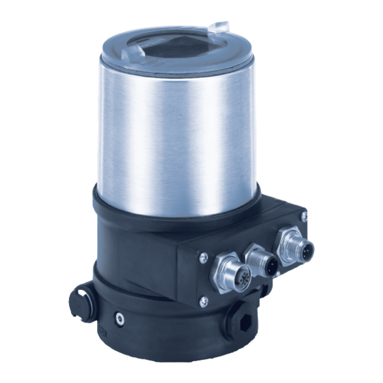
Type 8692, 8693 REV.2 System description Functions Transparent cap (below control module with display Type 8692 - Positioner (position controller) and keys) The position of the actuator (stroke) is regulated according to the Housing jacket position set-point value. The position set-point value can be specified by an external standard signal (or via field bus). Electrical connection housing (Connection option with circular Type 8693 - Process controller plug-in connector) The process controller is linked to a control circuit. The position Pressure limiting valve set-point value of the valve is calculated from the process set- point value and the process actual value via the control param- eters (PID controller). The process set-point value can be set by Exhaust air port an external signal. (Label: 3) Pilot air port (Label: 1) Electrical connection housing (Connection option with connection terminals) Additional exhaust air port (Label: 3.1) only for Types 23xx and 2103 with pilot-controlled control system for a high air flow rate from actuator size ø 125 / 130 Air intake filter Fig. -
Page 9: Technical Data
Type 8692, 8693 REV.2 Technical data TECHNICAL DATA Operating conditions Conformity WARNUNG The electromotive valves, types 8692 and 8693, are compliant Solar radiation and temperature fluctuations may cause mal- with EU directives as stated in the EU Declaration of Conformity functions or leaks. (if applicable). ▶ If the device is used outdoors, do not expose it unprotected Standards to the weather conditions. ▶ The permitted ambient temperature may not exceed the The applied standards, which are used to demonstrate conformity maximum value or drop below the minimum value. with the EU Directives, are listed in the EU-type examination cer- tificate and/ or the EU Declaration of Conformity (if applicable). Ambient temperature: T he permitted temperature range is Licenses given on the rating plate of the device. -
Page 10: Type Label
Type 8692, 8693 REV.2 Technical data Type label Mechanische Daten Dimensions see data sheet Type; features of the type code applicable to UL and ATEX Housing material o utside: PPS, PC, VA, interior: Example: Control function; pilot valve PA 6; ABS Supply voltage; pilot valve Sealing material NBR / EPDM 8692 -E3-...-0 PU02 Single act Pilot 3.0 24V Stroke range valve spindle 3...45 mm Maximum operating pressure Pmax 7 bar Tamb -10 - +55°C REV.2 Max. ambient temperature; S/N 1001 hardware revision Pneumatic data 00123456... -
Page 11: Electrical Data
Type 8692, 8693 REV.2 Technical data Electrical data for pressure drop from 7 to 6 bar absolute) WARNING o ptional: 130 l / min (for aeration and deaeration) (only single-acting Only circuits with limited power may be used for UL approved connections) components according to “NEC Class 2”. Connections Plug-in hose connector ø 6 mm / Protection class III as per DIN EN 61140 (VDE 0140-1) 1/4“ socket connection G1/8 Anschlüsse C able gland M16 x 1.5, size 22 (clamping area 5...10 mm) with connection terminals for cable cross-sections 0.14...1.5 mm² (24 V DC) or circular plug-in connectors (M12 x 1) (24 V DC, PROFIBUS DP, Devi- ceNet EtherNet/ IP, PROFINET I/O, Modbus TCP) Pilot valve operating voltage 2 4 V DC ± 10 %, max. residual ripple 10 % Power consumption < 5 W... -
Page 12: Operation
I nput resistance 70Ω Resolution 12 bit Symbol for position control Symbol for process control 0...5/10 V: I nput resistance 22 kΩ Resolution 1 2 bit (only 11 bit Symbol for the AUTOMATIC operating state for 0...5 V) Other symbols are displayed according to the activated func- tions. See operating instructions type 8692/8693 Analogue feedback max. current 1 0 mA (for voltage output 0...5/10 V) Abbreviated designation for the displayed process value load 0 ...560 Ω (for current output 0/4...20 mA) Unit of the displayed process Digital outputs galvanically isolated, PNP value current limitation 1 00 mA, output is clocked if overload occurs... -
Page 13: Function Of The Keys
Type 8692, 8693 REV.2 Operation Function of the keys The function of the 4 keys in the control field differs depending Display elements of on the operating state (AUTOMATIC or MANUAL) and operating the setting level: level (process level or setting level). Menu designation The function of the keys is displayed in the gray text field which M A I N is above the key. INPUT Submenu BUS.COMM X.TUNE Function of the keys on the process level: ADD.FUNCTION EXIT... -
Page 14: Operating States
Type 8692, 8693 REV.2 Operating states OPERATING STATES Function of the keys on the setting level: Type 8692/8693 has 2 operating states: Function of the Description of the function AUTOMATIC and MANUAL. keys Arrow key Scroll up in the menus AUTOMATIC In the AUTOMATIC operating state Increase numerical values MENU normal controlled operation is Arrow key Scroll down in the menus implemented. Decrease numerical values – MENU (The symbol for AUTOMATIC is shown on the display. (A bar runs... -
Page 15: Displays In The Automatic Operating State
Type 8692, 8693 REV.2 Operating states Displays in the AUTOMATIC operating Type 8692 Description of the display Type 8693 state Graphical display of SP and Type 8692 Description of the display Type 8693 PV with time axis SP / PV (t) MENU HOLD Actual position of the valve actuator (0 ... 100%) Graphical display of POS MENU CMD MANU... -
Page 16: Mastercode
Type 8692, 8693 REV.2 Operating levels OPERATING LEVELS Type 8692 Description of the display Type 8693 There is the process level and the setting level for the operation Automatic linearization of the P.LIN and setting of type 8692/8693. process characteristics Process level: The running process is displayed and operated on this level. MENU P.TUNE CMD/POS Operating state: A UTOMATIC – Displaying the process data Simultaneous display of the MANUAL – M anually opening and closing set-point position and the the valve actual position of the valve actuator (0 ... 100 %) -
Page 17: Installation
Type 8692, 8693 REV.2 Installation INSTALLATION 10.3 Installation on process valves, types 2103, 2300 and 2301 Only for positioners and process controllers without NOTE pre-assembled process valve. When mounting on process valves with a welded body, 10.1 Installation of devices for the Ex area follow the installation instructions in the operating instruc- When installing devices in the explosion-protected area, observe tions for the process valve. - Page 18 Type 8692, 8693 REV.2 Installation Guide rail During the installation, the collets of the pilot air ports must not be fitted to the actuator. → Aligning actuator with type 8692/8693: 1. A lign the pilot air ports of the actuator with the connection pieces of type 8692/8693 (see “Fig. 8”). Fastening screws Puck max. 1.5 Nm (1.1 Ibf ft) Fig. 9: Aligning the puck Connection piece NOTE Damage to the PCB or malfunction. Pilot air ports ▶ Ensure that the puck lies flat on the guide rail. → Push type 8692/8693 without turning it onto the actuator until no gap is visible on the form seal.
-
Page 19: Installation On Process Valves, Series 26Xx And 27Xx
Type 8692, 8693 REV.2 Installation 10.4 Installation on process valves, series Ensure that the pneumatic connections of type 26xx and 27xx 8692/8693 and those of the valve actuator are situated preferably vertically one above the other (see “Fig. 11”). The installation of the switch spindle is described in the operating instructions for type 8692/8693. You can find NOTE the instructions on the Bürkert homepage. To comply with the degree of protection IP65 / IP67, do not → Place type 8692/8693 onto the actuator. In doing so, align the fasten the fastening screws too tightly. - Page 20 Type 8692, 8693 REV.2 Installation → Establish the pneumatic connection between type 8692/8693 Control function Pneumatic connection type 8692, 8693 and the actuator. with actuator NOTE Pilot air Pilot air port actuator outlet Damage or malfunction due to ingress of dirt and moisture. types 8692 ▶ To comply with the degree of protection IP65 / IP67, connect and 8693 the pilot air outlet which is not required to the free pilot air port of the actuator or seal with a plug.
-
Page 21: Pneumatic Connection
Type 8692, 8693 REV.2 Installation 10.5 Pneumatic connection DANGER Exhaust air port Risk of injury from high pressure in the system/device. Label: 3 ▶ Before working on the system or device, switch off the pres- sure and vent/drain lines. Pilot air port Observe the following for the proper functioning of the Label: 1 device: Additional ▶ The installation must not cause back pressure to build exhaust air port Label: 3.1... -
Page 22: Electrical Installation
Type 8692, 8693 REV.2 Electrical installation ELECTRICAL INSTALLATION 11.1 Safety instructions DANGER There are 2 connection options for type 8692/8693: Risk of injury due to electrical shock. • Multi-pole with circular plug-in connector ▶ Before reaching into the system, switch off the power supply • Cable gland with connection terminals and secure to prevent reactivation. ▶ Observe applicable accident prevention and safety regula- Signal values tions for electrical equipment. Operating voltage: 24 V DC Set-point value WARNING (process/position controller): 0 ...20 mA; 4...20 mA 0...5 V; 0...10 V Risk of injury from improper installation. -
Page 23: Electrical Installation With Circular Plug-In Connector
Type 8692, 8693 REV.2 Electrical installation 11.2 Electrical installation with circular X1 - M12 circular connector, 8-pole plug-in connector Pin Wire Assignment color* Procedure: Input signals of the control centre (e.g. PLC) → Connect type 8692/8693 according to the tables. white Digital input + When the operating voltage is applied, type 8692/8693 is Set-point value + (0/4...20 mA / 0...5/10 V) - Page 24 Process actual 2 (compensation) * Adjustable via software (see operating instructions type 8692/8693 Rev.2 “Setting the input signal”). ** Position of the switch, see “Fig. 14: Cable gland connection”. Tab. 5: X5 - M8 circular plug, 4-pole, input signals process actual value...
-
Page 25: Electrical Installation With Cable Gland
Type 8692, 8693 REV.2 Electrical installation 11.3 Electrical installation with cable gland → Place the connection cover with inserted seal onto the elec- trical connection housing and tighten cross-wise (tightening WARNING torque max. 0.7 Nm (0.5 Ibf ft)). NOTE Risk of injury from improper installation. ▶ Installation may be carried out by authorized technicians Damage or malfunction due to ingress of dirt and moisture. only and using the appropriate tools. To comply with the degree of protection IP65 / IP67: Risk of injury from unintentional activation of the system and ▶... - Page 26 Type 8692, 8693 REV.2 Electrical installation 11.3.1 Input signals from the control center (e.g. 11.3.3 Process actual value input (for Type 8693 PLC) only) Terminal Assignment Input type* Terminal Assignment Switch ** Digital input + 4...20 mA GND (identical to GND - internally operating voltage) Set-point value GND...
- Page 27 Not assigned Tab. 10: Terminal assignment; operating voltage * Adjustable via software When the operating voltage is applied, type 8692, 8693 is (see Operating Instructions type 8692/8693 Rev. 2). operating. ** The switch is situated under the connection cover → Now make the required basic settings and adjustments for (see “Fig. 14: Cable gland connection” ). the position controller/process controller. For a description Tab.
-
Page 28: Start-Up
Type 8692, 8693 REV.2 Start-up START-UP Setting the input signal (INPUT) A detailed description of the start-up and operating pro- This setting is used to select the input signal for the set-point cedures can be found at our homepage in the operating value. instructions for type 8692/8693. Set the input signal as follows: 12.1 Safety instructions → Press MENU for 3 s. Switching from process level WARNING setting level. → Select INPUT. Risk of injury from improper operation. Improper operation may result in injuries as well as damage to → Select ENTER. The possible input signals for INPUT the device and the area around it. are displayed. - Page 29 Type 8692, 8693 REV.2 Start-up Automatic adjustment of the position controller to To stop X.TUNE, press the left or right selection key the operating conditions (X.TUNE) STOP WARNING Automatically adjust the position controller as follows: → Press MENU for 3 s. Switching from process level Danger due to the valve position changing when the X.TUNE setting level.
-
Page 30: Start-Up Type 8693
Type 8692, 8693 REV.2 Start-up 12.3 Start-up type 8693 12.3.1 Basic settings of the process controller → In the main menu (MAIN) select the P.CONTROL function and To operate the position controller as a process controller, implement implement the basic settings the following steps: Set up the process controller as follows: 1. Setting up the position controller: → Press MENU for 3 s. Switching from process level Description see “12.2.1 Specifying the basic settings”. setting level. → Select P.CONTROL. Selection in the main menu 2. Setting up the process controller: (MAIN). - Page 31 Type 8692, 8693 REV.2 Start-up Parameterize the process controller as follows: P.CONTROL - settings: → Press MENU for 3 s. Switching from process level PID.PARAMETER Parameterization of the process controller setting level. Insensitivity range (dead band) of the PID DBND 0,1 % → Select P.CONTROL. Selection in the main menu process controller (MAIN). 0,00 Amplification factor of the process controller → Select ENTER. The submenu options for the basic Reset time setting are displayed. → Select PID.PARAMETER.
-
Page 32: Ethernet/Ip, Profinet And Modbus Tcp
Type 8692, 8693 REV.2 EtherNet/IP, PROFINET and Modbus TCP ETHERNET/IP, PROFINET AND 12.3.2 Manually changing the process set-point value MODBUS TCP Procedure: The quickstart describes only the electrical installation of type 8692, 8693 and the specification of the basic settings. 1. Set the set-point value default on the setting level: The settings for the bus communication via the BUS. In the main menu (MAIN), select the P.CONTROL function COMM menu are described in the operating instructions internal ENTER SETUP ENTER P.CONTROL SP-INPUT of type 8692, 8693. -
Page 33: View Field Bus Connection
Type 8692, 8693 REV.2 EtherNet/IP, PROFINET and Modbus TCP 13.2 View Field bus connection 13.4 Electrical connection DANGER Risk of injury due to electric shock. ▶ Before reaching into the system, switch off the power supply and secure to prevent reactivation. ▶ Observe the applicable accident prevention regulations and X6 - M12 safety regulations for electrical equipment. circular WARNING connector, X7 - fieldbus 4-pole connection M12 Risk of injury from improper installation. -
Page 34: Bus Status Display
Type 8692, 8693 REV.2 EtherNet/IP, PROFINET and Modbus TCP 13.5 Bus status display X6 - M12 circular connector, 4-pole: Wire color* Assignment The bus status is indicated on the display on the device. brown Operating voltage + 24 V DC Display Device Explanation Troubleshooting state Not assigned (is displayed approx. every blue Operating voltage GND 3 seconds) Not assigned Device is con- * The indicated colors refer to the connection cable available as an nected correctly accessory (918038). Online, to the bus, the Tab. 14: X6 - M12 circular connector, 4-pole (operating voltage) -
Page 35: 14 Büs Option
Type 8692, 8693 REV.2 büS OPTION büS OPTION 13.5.1 BUS.COMM – Settings on type 8692, 8693 Set the following menu options in the BUS.COMM menu for 14.1 Electrical installation start-up of the EtherNet version: Procedure: Activate or deactivate approach of the → Connect type 8692, 8693 according to the tables. BUS FAIL safety position A setscrew with nut is located on the electrical connection housing for connection of the technical ground. SafePos off – T he actuator remains in the Selection →... -
Page 36: Electrical Installation - Büs
Type 8692, 8693 REV.2 büS OPTION 14.3 Electrical installation - büS X6 - M12 circular connector, 4-pole: Wire color* Assignment DANGER brown Operating voltage + 24 V DC Risk of injury due to electric shock. Not assigned ▶ Before reaching into the system, switch off the power supply blue Operating voltage GND and secure to prevent reactivation. Not assigned ▶ Observe the applicable accident prevention regulations and * The indicated colors refer to the connection cable available as an safety regulations for electrical equipment. accessory (918038). Tab. 17: X6 - M12 circular connector, 4-pole (operating voltage) WARNING Electrical installation with or without büS network:... -
Page 37: Safety End Positions
Type 8692, 8693 REV.2 Safety end positions SAFETY END POSITIONS REMOVAL OF TYPE 8692, 8693 Safety end positions after WARNING failure of the Actuator Designation electrical pneumatic Risk of injury from improper disassembly. system auxiliary auxiliary power ▶ Removal may be carried out by authorized technicians only power and using the appropriate tools. -
Page 38: Disconnecting The Pneumatic Connections
Type 8692, 8693 REV.2 Removal of Type 8692, 8693 16.1 Disconnecting the pneumatic 16.2 Disconnecting electrical connections connections DANGER DANGER Risk of injury due to electric shock. Risk of injury from high pressure. ▶ Before reaching into the device or the equipment, switch off the power supply and secure to prevent reactivation. ▶ Before loosening lines and valves, turn off the pressure and vent the lines. ▶ Observe the applicable accident prevention regulations and safety regulations for electrical equipment. -
Page 39: Removing Type 8692, 8693
Type 8692, 8693 REV.2 Accessories 16.3 Removing Type 8692, 8693 ACCESSORIES 17.1 Communications software Types 8692, 8693 The PC software Bürkert-Communicator is designed for commu- nication with Bürkert devices. Fastening screws A detailed description for installing and operating the PC software can be found in the associated operating instructions. Fastening Download the software from: www.buerkert.de screws Type 8692, 8693 with Type 8692, 8693 with process valve process valve 17.2 USB interface of Type 2103, 2300 or 2301 of series 26xx or 27xx To communicate with the devices, the PC requires a USB interface and the USB büS interface set available as an accessory. Fig. 21: Disconnecting electrical connections USB büS interface set... -
Page 40: Packaging, Transport, Storage
Type 8692, 8693 REV.2 Packaging, transport, storage PACKAGING, TRANSPORT, STORAGE NOTE Transportschäden. Inadequately protected devices may be damaged during transportation. ▶ Protect the device against moisture and dirt in shock-resis- tant packaging during transportation. ▶ Prevent the temperature from exceeding or dropping below the permitted storage temperature. Incorrect storage may damage the device. ▶ Store the device in a dry and dust-free location. ▶ Storage temperature: -20…+65 °C (-40...158 °F). 18.1 DISPOSAL NOTE Damage to the environment caused by parts contaminated with media. - Page 41 www.burkert.com...
Need help?
Do you have a question about the 8692 and is the answer not in the manual?
Questions and answers