
Related Manuals for Burkert TopControl Basic 8694 REV.2


Summary of Contents for Burkert TopControl Basic 8694 REV.2
- Page 1 Type 8694 REV.2 Positioner TopControl Basic Electropneumatic position controller Elektropneumatischer Stellungsregler Positionneur électropneumatique Quickstart English Deutsch Français...
- Page 2 We reserve the right to make technical changes without notice. Technische Änderungen vorbehalten. Sous réserve de modifications techniques. © Bürkert Werke GmbH & Co. KG, 2008-2020 Operating Instructions 2002/02_EU-ML_00815305 / Original DE...
-
Page 3: Table Of Contents
Type 8694 REV.2 Table of contents PNEUMATIC INSTALLATION ..........14 ABOUT THESE INSTRUCTIONS .......... 4 Symbols ............... 4 ELECTRICAL INSTALLATION ..........15 1.2 Definition of terms ............4 9.1 Safety instructions ............. 15 9.2 Electrical installation without fieldbus INTENDED USE ..............5 communication ............15 BASIC SAFETY INSTRUCTIONS .......... 5 Electrical installation, IO-Link ........ -
Page 4: About These Instructions
▶ Persons, who work on the device, must read and understand recommendations. these instructions. Refers to information in these instructions or in other The operating instructions can be found on the Internet at: documentation. www.burkert.com ▶ Designates an instruction to prevent risks. Symbols → designates a procedure that must be carried out. DANGER! Indicates a result. Warns of an immediate danger. -
Page 5: Intended Use
Type 8694 REV. 2 Intended use INTENDED USE BASIC SAFETY INSTRUCTIONS These safety instructions do not consider any contingencies or inci- The Positoner Type 8694 REV.2 is designed to be mounted dents which occur during installation, operation and maintenance. on pneumatic actuators of process valves for the control of media. -
Page 6: General Information
▶ Observe intended use. Tel. + 49 (0) 7940 - 10 91 111 Fax + 49 (0) 7940 - 10 91 448 ATTENTION! E-mail: info@burkert.com Electrostatic sensitive components or modules. International The device contains electronic components which react sen- sitively to electrostatic discharge (ESD). Contact with electro-... -
Page 7: Structure And Function
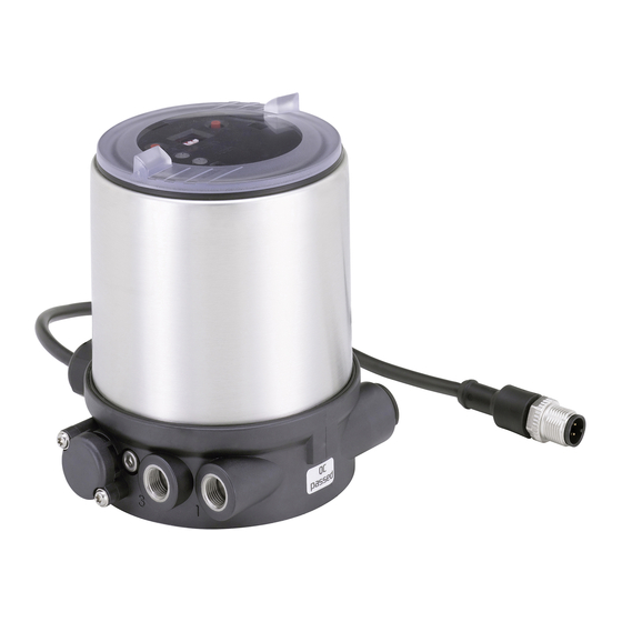
Type 8694 REV. 2 Structure and function STRUCTURE AND FUNCTION Electrical connection (cable gland or circular plug-in connector) Positioner Pressure limiting valve Communications interface DIP Switches Actuator Valve body Exhaust air port (label: 3) Pilot air port Actuator + Valve body = Process valve Buttons (label: 1) Basic housing Fig. 1: Structure 1 Positioner Type 8694 is an electropneumatic position controller for Pilot air outlet only for... -
Page 8: Technical Data
Type 8694 REV.2 Technical data TECHNICAL DATA Type labels Conformity Type, Features of the type code applicable to UL and ATEX Control function, pilot valve, In accordance with the EU Declaration of conformity, the Supply voltage pilot valve 8694 -E3-...-0 PU02 positioner Type 8694 is compliant with the EU Directives. Single act Pilot 3.0 24V Max. operating pressure Pmax 7 bar Standards Tamb -10 - +60 °C REV.2 Ambient temperature, version S/N 1001 The applied standards, which verify conformity with the EU Serial number, CE marking... -
Page 9: Pneumatic Data
Type 8694 REV. 2 Technical data Ambient temperature see type label Connections Plug-in hose connector ∅ 6 mm (1/4“) Socket connection G1/8 Degree of protection Electrical data Evaluated by the manufacturer: Evaluated by UL: WARNING! IP65 / IP67 according to EN 60529* UL Type 4x Rating* Operating altitude up to 2000 m above sea level Only circuits with limited power may be used for UL approved components according to “NEC Class 2”. -
Page 10: Factory Settings
These instructions can be found on the Internet at Total power consumption max. 3,5 W www.burkert.com. 1) Actuator supply is galvanically isolated from system supply in accor- 2) Without change to the settings via the communications software a dance with IEC 60664 and for electrical safety in accordance with linear characteristic is stored in FREE. -
Page 11: Installation
Type 8694 REV. 2 Installation INSTALLATION Installing the positioner on process valves belonging to series 2103 and Only for positioner without pre-assembled process valve. 23xx ATTENTION! When mounting on process valves with a welded con- Safety instructions nection, follow the installation instructions in the operating instructions for the process valve. DANGER! When the positioner is being installed, the collets of the Risk of injury from high pressure in the equipment/device. -
Page 12: Installing The Positioner On Process Valves Belonging To Series 26Xx And 27Xx
Type 8694 REV.2 Installation Installing the positioner on process → Push the positioner, without turning it, onto the actuator until no gap is visible on the form seal. valves belonging to series 26xx and 27xx ATTENTION! Procedure: Too high torque when screwing in the fastening screw does Guide rail not ensure degree of protection IP65 / IP67. - Page 13 Type 8694 REV. 2 Installation Ensure that the pneumatic connections of the positioner and those of the actuator are situated preferably vertically Pilot air outlet 2 one above the other (see “Fig. 8”). Pilot air outlet 2 ATTENTION! Too high torque when screwing in the fastening screw does Fastening screws not ensure degree of protection IP65 / IP67. max.
-
Page 14: Pneumatic Installation
Type 8694 REV.2 Pneumatic installation PNEUMATIC INSTALLATION Control function A (CFA) Process valve closed in rest position (by spring force) DANGER! ∅ 80, ∅ 100 Actuator size Risk of injury from high pressure in the equipment/device. ∅ 125 ▶ Before working on equipment or device, switch off the pressure Pilot air outlet and deaerate/drain lines. Exhaust air port (label: 3) Upper pilot air port Pilot air port... -
Page 15: Electrical Installation
Type 8694 REV. 2 Electrical installation ELECTRICAL INSTALLATION Important information for the problem-free functioning of the device: All electrical inputs and outputs of the device are not galvanically ▶ The installation must not cause back pressure to build up. isolated from the supply voltage. ▶ Select a hose for the connection with an adequate Safety instructions cross-section. DANGER! ▶ The exhaust air line must be designed in such a way that no water or other liquid can get into the device through Risk of electric shock. - Page 16 Type 8694 REV.2 Electrical installation 9.2.1 Electrical installation with cable gland Input signals from the control centre (e.g. PLC) ATTENTION! Terminal Configuration External circuit, signal level Breakage of the pneumatic connection pieces due to rota- Set-point value + + (0/4 – 20 mA) tional impact. ▶...
- Page 17 Type 8694 REV. 2 Electrical installation 9.2.2 Connection type 3-wire or 4-wire Body casing Setting via communication software Connection type 4-wire (factory setting) Seal Body casing The set-point value input is designed as a differential input, i.e. the GND lines of the set-point value input and the supply Basic housing voltage are not identical. Note: If the GND signals of the set-point value input and the Fig. 12: Position of the seal in the body casing supply voltage are connected, the 3-wire connection type must →...
- Page 18 Type 8694 REV.2 Electrical installation 9.2.3 Electrical installation 24 V DC with circular Connection type 3-wire plug-in connector The set-point value input is related to the GND line of the → Connect the positioner according to the table. supply voltage, i.e. setpoint input and supply voltage have a common GND line. 0/4 – 20 mA Fig.
-
Page 19: Electrical Installation, Io-Link
Type 8694 REV. 2 Electrical installation Electrical installation, IO-Link Operating voltage Wire Configuration External circuit color green 24 V DC ± 25 % max. residual ripple 10 % yellow + 24 V Tab. 9: Pin assignment, operating voltage Fig. 14: Pin assignment, Port Class B Output signals to the control center (e.g. PLC) - (required for analogue output option only) Designation Configuration... -
Page 20: Electrical Installation, Büs
Type 8694 REV.2 Start-up Electrical installation, büS START-UP 10.1 Safety instructions WARNING! Risk of injury from improper operation. Improper operation may result in injuries as well as damage to the device and the area around it. ▶ Before start-up, ensure that the operating personnel are familiar with and completely understand the contents of the operating instructions. Fig. - Page 21 Type 8694 REV. 2 Start-up ATTENTION! Communications Avoid maladjustment of the controller due to an incorrect interface pilot pressure or applied operating medium pressure. LED 1 ▶ Run X.TUNE whenever the pilot pressure (= pneumatic aux- LED 2 iliary energy) is available during subsequent operation. DIP Switches •...
-
Page 22: 10.3 Setting With Bürkert Communicator
Type 8694 REV.2 Start-up 10.3.1 Connecting IO-Link device with Bürkert ATTENTION! Communicator Breakage of the pneumatic connection pieces due to rota- Required components: tional impact. • Communications software: Bürkert Communicator for PC ▶ When unscrewing and screwing in the transparent cap, do not • USB-büS interface set (see accessories) hold the actuator of the process valve but the basic housing. •... -
Page 23: 10.4 Io-Link
Type 8694 REV. 2 Start-up 10.4 IO-Link Communications 10.4.1 Information, IO-Link interface IO-Link is an internationally standardized IO technology (IEC LED 1 61131-9) to enable sensors and actuators to communicate. LED 2 IO-Link is a point-to-point communication with 3-wire connection DIP Switches technology for sensors and actuators and unshielded standard 1 2 3 4... -
Page 24: 10.5 Büs
ATTENTION! data and acyclic parameters are available on the Internet. Breakage of the pneumatic connection pieces due to rota- Download from: tional impact. www.burkert.com / Type 8694 / Software ▶ When unscrewing and screwing in the transparent cap, do not hold the actuator of the process valve but the basic housing. 10.5 büS 10.5.1 Information, büS Transparent cap büS is a system bus developed by Bürkert with a communication... - Page 25 Type 8694 REV. 2 Control and display elements 11.5.1 Operating state Communications interface AUTOMATIC (AUTO) Normal controller mode is implemented and monitored in AUTO- LED 1 MATIC operating state. LED 2 DIP Switches MANUAL (MANU) 1 2 3 4 In MANUAL operating state the valve can be opened and closed Button 2 manually via the buttons.
- Page 26 Type 8694 REV.2 Control and display elements 11.5.2 Functions of the buttons MANUAL operating state (DIP switch 4 set to ON): Button Function Communications Aerate (manually open / close the actuator) interface LED 1 Deaerate (manually open / close the actuator) LED 2 Longer than 10 s (< 30 s, LED 2 flashes at 5 Hz): 1 and 2 DIP Switches Device restart simulta- 1 2 3 4...
- Page 27 Type 8694 REV. 2 Control and display elements 11.5.3 Function of the DIP switches 11.5.4 Display of the LEDs Function Communications switches 1 2 3 4 interface LED 1 Reversal of the effective direction of the set-point value (set-point value 20 – 4 mA corresponds to LED 2 position 0 – 100 %), descending (DIR.CMD) DIP Switches Normal effective direction of the set-point value 1 2 3 4 (set-point value 4 – 20 mA corresponds to Button 2 position 0 – 100 %), ascending...
- Page 28 Type 8694 REV.2 Control and display elements 11.5.5 Device status display 11.5.6 Valve mode + warnings The device status LED 1 (RGB) show the device status. Displays in valve mode + warnings: • Valve position: open, half-way, closed The user can set the following LED modes for the display of device status and valve position. • Device status: failure, function check, out of specification, • Valve mode maintenance required (according to NAMUR) •...
- Page 29 Type 8694 REV. 2 Control and display elements If several device statuses exist simultaneously, the device status If several device statuses exist simultaneously, the device status with the highest priority is displayed. with the highest priority is displayed. The priority is determined by the severity of the deviation from controlled operation (red LED = failure = highest priority). Valve Device status position Failure Function Out of Maintenance Status display in accordance with NE 107, edition 2006-06-12 required check specifi-...
-
Page 30: Safety End Positions
Type 8694 REV.2 Safety end positions 11.5.8 Status LED, green SAFETY END POSITIONS LED 2 (green) indicates the following: Safety positions after failure Actuator of the auxiliary power Color Status Description Designation system green is lit electrical pneumatic is not lit IO-Link communication inactive pilot valve system with high... -
Page 31: Accessories
665702 A detailed description and precise schedule of the procedure Wrench for opening or closing the trans- 674077 for the installation and operation of the software can be found parent cap in the associated documentation. Connection cable M12 x 1, 8-pole 919061 Communication software Bürkert Information at Download the software at: www.burkert.com Communicator www.burkert.com USB-büS interface set: USB-büS interface set 2 (büS stick + 0.7 m 772551 cable with M12 plug) büS adapter for büS service interface 773254 (M12 on büS service interface Micro-USB) büS cable extension (M12 pin to M12 772404 socket), length 1 m... -
Page 32: Transportation, Storage, Disposal
Type 8694 REV.2 Transportation, storage, disposal TRANSPORTATION, STORAGE, DISPOSAL ATTENTION! Damage in transit due to inadequately protected devices. ▶ Protect the device against moisture and dirt in shock-resi- stant packaging during transportation. ▶ Observe permitted storage temperature. ATTENTION! Incorrect storage may damage the device. ▶... - Page 34 www.burkert.com...
Need help?
Do you have a question about the TopControl Basic 8694 REV.2 and is the answer not in the manual?
Questions and answers