Burkert 2103 Series Additional Instructions
Remote-positioner, installation on process valves with internal air flow
Hide thumbs
Also See for 2103 Series:
- Operating instructions manual (142 pages) ,
- Quick start manual (53 pages) ,
- Operating instructions manual (50 pages)
Table of Contents
Advertisement
Quick Links
Type
8635
Remote-Positioner
Installation on process valves with internal air flow (series 2103, 2300, 2301)
Anbau an Prozessventile mit interner Luftführung (Reihe 2103, 2300, 2301)
Intégration sur des vannes de process dotées d'un système interne de guidage d'air
(séries 2103, 2300, 2301)
Zusatzanleitung
English
Deutsch
Français
Advertisement
Table of Contents

Related Manuals for Burkert 2103 Series


Summary of Contents for Burkert 2103 Series
- Page 1 Type 8635 Remote-Positioner Installation on process valves with internal air flow (series 2103, 2300, 2301) Anbau an Prozessventile mit interner Luftführung (Reihe 2103, 2300, 2301) Intégration sur des vannes de process dotées d'un système interne de guidage d'air (séries 2103, 2300, 2301) Zusatzanleitung English Deutsch...
-
Page 2: Table Of Contents
Electrical connection of the position sensor ....8 START-UP ................9 The operating instructions for the process valves can be found on the Internet at: www.burkert.com REMOVAL ................10 Removing the position sensor ........10 Symbols ▶ Highlights instructions to avoid a danger. -
Page 3: Remote Operation
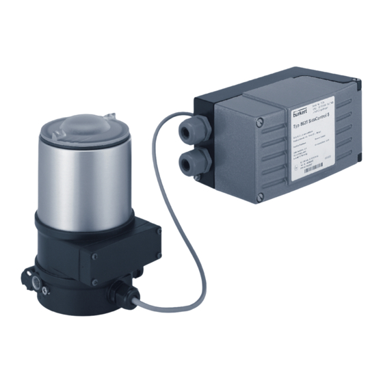
Type 8635, Remote-Positioner Remote operation REMOTE OPERATION 2.1.2 Dimensions In the case of remote operation, the positioner has no position sensor in the form of a rotary position sensor, but is connected to an external position sensor. The 2.5 m long connection cable is pre-assembled on the positioner. -
Page 4: Assembling The Position Sensor
Type 8635, Remote-Positioner Assembling the position sensor ASSEMBLING THE POSITION Installing attachment kit on the SENSOR actuator NOTE! DANGER! To install process valves with welded body, follow the Risk of injury from high pressure and discharge of medium. installation instructions in the operating instructions for the ▶... -
Page 5: Mounting Remote Position Sensor On The Actuator
Type 8635, Remote-Positioner Assembling the position sensor NOTE! Switch cam Improper assembly may damage the lip seal in the guide Switch spindle complete element. Guide element The lip seal is pre-mounted in the guide element and must be "locked into position" in the undercut. Form seal ▶... - Page 6 Type 8635, Remote-Positioner Assembling the position sensor → Push potentiometer slide downwards. Slide Potentiometer Switch cam Switch cam with attached slide Connection piece of the position sensor Fig. 6: Inserting slide into switch cam Pilot air ports of the actuator →...
-
Page 7: Pneumatic Connection Of The Position Sensor
Type 8635, Remote-Positioner Assembling the position sensor Pneumatic connection of the position sensor DANGER! Risk of injury from high pressure and discharge of medium. ▶ Before working on the device or system, switch off the pres- sure. Vent or drain lines. Fastening screws (2x) Fig. -
Page 8: Electrical Connection Of The Position Sensor
Type 8635, Remote-Positioner Assembling the position sensor Electrical connection of the position Length of the pilot air line: sensor The length of the pilot air line should be adjusted to the actuator size. The dead space volume which occurs DANGER! due to the pilot air line may negatively affect the control Danger due to electrical shock. -
Page 9: Start-Up
Type 8635, Remote-Positioner Start-up START-UP → When tightening the cable gland, note the position of the plug-in connection. See marked area in the following "Fig. 12". WARNING! NOTE! Risk of injury due to incorrect operation. The cable in the housing must have a minimum length, but ▶... -
Page 10: Removal
Type 8635, Remote-Positioner Removal REMOVAL Removing the position sensor → Disconnect the pneumatic connections. DANGER! → Switch off the power supply and secure it against reactivation. Risk of injury from high pressure and discharge of medium. → Unscrew body casing by rotating it in a counterclockwise ▶... -
Page 11: Transportation, Storage, Disposal
Type 8635, Remote-Positioner Transportation, storage, disposal TRANSPORTATION, STORAGE, Slide DISPOSAL Switch cam CAUTION! Risk of injury due to heavy device. A heavy device can fall down and cause injury during transport or assembly work. ▶ Do not transport, install or remove a heavy device without the aid of a second person. - Page 12 We reserve the right to make technical changes without notice. Technische Änderungen vorbehalten. Sous réserve de modifications techniques. © Bürkert Werke GmbH & Co. KG, 2018 Operating Instructions 1803/00_EU-ML_00810707 / Original DE...
Need help?
Do you have a question about the 2103 Series and is the answer not in the manual?
Questions and answers