
Subscribe to Our Youtube Channel
Related Manuals for JUMO IMAGO F3000


Summary of Contents for JUMO IMAGO F3000
- Page 1 Process controller for the meat processing industry B 70.0101 Operating Instructions for equipment manufacturers 10.01 /00385193...
-
Page 3: Table Of Contents
Logic module (slot 6) ................... 17 4.2.8 Relay module (slot 6) ................... 17 4.2.9 Connector 13 ....................... 17 4.2.10 Connector 14 ....................... 18 4.2.11 Connector 15 ....................... 18 4.2.12 Connector 16 ....................... 18 Electrical isolation ....................19 IMAGO F3000 / 10.01... - Page 4 Program source ....................43 6.9.7 Process step editor ..................... 44 6.9.8 Temperature unit ....................44 6.9.9 Password (config) ....................45 6.10 MENU parameterization ..................45 6.10.1 Controller parameter sets ..................45 6.10.2 Limit comparators ....................45 IMAGO F3000 / 10.01...
- Page 5 Interfaces ......................63 7.4.2 Special settings in interface operation with mTRON modules ......63 7.4.3 Analog inputs ....................... 64 7.4.4 Controller ......................65 7.4.5 Core changeover ....................67 7.4.6 Program source ....................68 Parameterization ....................70 IMAGO F3000 / 10.01...
- Page 6 Logic and alarm functions ................... 79 7.7.8 Fan control ......................82 7.7.9 Math/logic ......................83 7.7.10 Software locks ..................... 87 7.7.11 Operating hours counter ..................87 7.7.12 Production data ....................88 Setup data info ..................... 88 IMAGO F3000 / 10.01...
-
Page 7: Introduction
This could endanger your rights under the instrument warranty. In such a case, please contact your local representative or the main factory. Technical Technical data can be found on the Internet at: www.jumo.net data Products Electronic controllers... -
Page 8: Typographical Conventions
The markers in the text are arranged as continuous superscript numbers. Instructions for This sign marks the description of a required action. The individual action steps are indicated by this asterisk, e.g. h Insert the instrument into the panel cut-out from the front. IMAGO F3000 / 10.01... -
Page 9: Representation
If a key has a multiple function, then the text used it that which corresponds to the function at the moment. Menu items Small arrows between the words indicate a se- File save as quence of commands to be performed one after another. IMAGO F3000 / 10.01... - Page 10 1 Introduction IMAGO F3000 / 10.01...
-
Page 11: Identifying The Instrument Version
(5) Interface for teleservice and visualization no interface Interface RS422/485 (MODbus slave, connector 13) (6) Extra codes no extra code Plug & Play memory (7) Approvals none Underwriters Laboratories Inc. (UL) Order code Order example 700101 / 200110 IMAGO F3000 / 10.01... -
Page 12: Delivery Package
Input module: 4 analog inputs, 5 logic inputs 70/00398351 I/O module: 4 analog inputs, 5 logic inputs, 70/00398352 2 analog outputs Logic module: 11 logic inputs, 5 relay outputs (make contacts) 70/00398350 Interface for teleservice and visualization, 70/00398353 RS422/485 (MODbus slave) IMAGO F3000 / 10.01... -
Page 13: Installation
3 Installation Dimensions Portrait format Front panel cut-out to ISO 43 700 Landscape 91.6 format +1.3 Schalttafelausschnitt nach DIN ISO 43700 Front panel cut-out to ISO 43 700 IMAGO F3000 / 10.01... -
Page 14: Mounting
It is resistant to organic solvents (such as ethyl alcohol, turpentine substitute, P1, xylol and the like). It is not resistant to corrosive acids or lyes, abrasives, or cleaning with high-pressure cleaners! IMAGO F3000 / 10.01... -
Page 15: Electrical Connection
Do not connect any additional loads to the supply terminals of the equipment. The equipment is not suitable for installation in Ex areas (areas with an explosion hazard). IMAGO F3000 / 10.01... -
Page 16: Connection Diagram
LO level: -30 to +6V 18 COM 18 COM 18 COM 18 COM 18 COM HI level: 13 to 30V Analog output No. Symbol 0(4) — 20mA 19 + 21 + 0(2) — 10V 20 - 22 - configurable IMAGO F3000 / 10.01... -
Page 17: I/O Module (Slot 2)
56 COM 56 COM 56 COM 56 COM 56 COM Relay output No. Symbol 3A 230V 57 P 59 P 61 P 63 P 65 P 58 S 60 S 62 S 64 S 66 S IMAGO F3000 / 10.01... -
Page 18: Universal Interface (Slot 3)
96 S 98 S 100 S 91 S 94 S Relay output No. Symbol 3A 230V 101 P 103 P 105 P 107 P 109 P 102 S 104 S 106 S 108 S 110 S IMAGO F3000 / 10.01... -
Page 19: Logic Module (Slot 6)
132 S 4.2.9 Connector 13 Teleservice, RS 422 RS 485 Symbol visualization RS422/485 interface 4 RxD (+) 8 RxD/TxD B(-) 9 RxD (-) 3 RxD/TxD A(+) 3 TxD (+) 8 TxD (-) 5 GND 5 GND IMAGO F3000 / 10.01... -
Page 20: Connector 14
Plug & Play interface 4.2.11 Connector 15 Connection for Diagram Symbol Setup connector PC interface with TTL/RS232 converter 4.2.12 Connector 16 Connection Assignment Symbol Supply voltage, L1 phase/line as per nameplate N neutral PE protective earth IMAGO F3000 / 10.01... -
Page 21: Electrical Isolation
4 Electrical Connection 4.3 Electrical isolation IMAGO F3000 / 10.01... - Page 22 4 Electrical Connection IMAGO F3000 / 10.01...
-
Page 23: Instrument Description
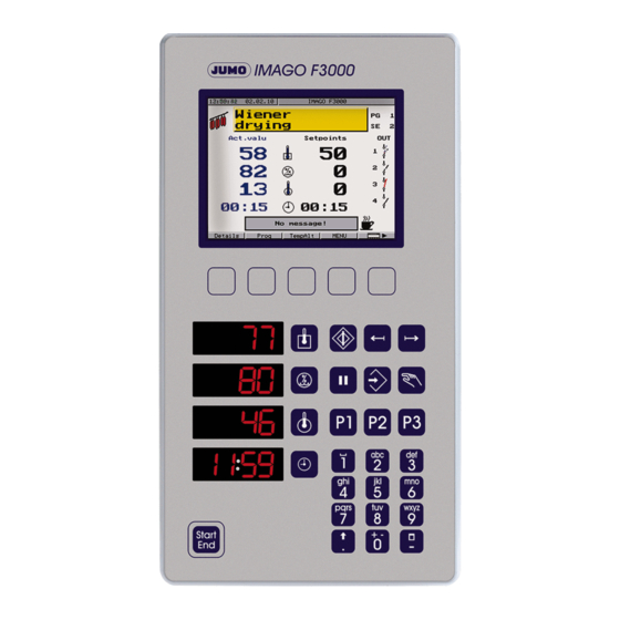
Color display Softkeys with variable meanings Freely assignable function keys Keypad for numerical and text entry Keys for temporary alteration of the remaining segment time LED displays Start/end key for starting and ending the program IMAGO F3000 / 10.01... - Page 24 In this format the color display and the softkeys are placed at the left. The format function keys correspond to those in the portrait version of the instrument, so it is not necessary to provide another detailed description. IMAGO F3000 / 10.01...
-
Page 25: Color Screen
Present meaning of soft- Pressing on changes the meaning keys of all the other function keys v Chapter 6.2.2 “Program entry” Instrument status Manual operation, automatic operation, pause, program end Softkeys Short-action keys with tactile feedback IMAGO F3000 / 10.01... -
Page 26: Keypad For Numerical And Text Entry
No.1 from the program list Program2 starts program No.2 from the program list Program3 starts program No.3 from the program list The key assignments can be altered within the setup program. v Chapter 7.7.2 “Function keys” IMAGO F3000 / 10.01... -
Page 27: Led Displays
The program is selected from a list or from program icons. The current program is stopped, without a confirmation query, and the instru- ment returns to the basic status. v Chapter 6.3 “Start program” Further info IMAGO F3000 / 10.01... -
Page 28: Operating Summary
Program table or ..program icons Step on screen in loop Program entry v Chapter 6.2.2 “Program entry” Production data Can only be activated via setup v Chapter 7.7.12 “Production data” Start delay v Chapter 6.3 “Start program” IMAGO F3000 / 10.01... -
Page 29: Operation
This process step contains the information on the standby condition of the instrument when no program is running. This is defined in the setup program. v Chapter 7.2 “Process steps” v Chapter 7.4.6 “Program source” IMAGO F3000 / 10.01... -
Page 30: Program Design
The comfortable way of working is to enter the process steps in the setup program, and transfer them to the instrument afterwards. If a few corrections are required, these can be made directly on the instrument. v Chapter 6.9.7 “Process step editor” IMAGO F3000 / 10.01... -
Page 31: Program Entry
Programs can not only be put together on the instrument, but also very comfortably by using the PC. The software to do this is available as an accessory, called Program editor IMAGO F3000. h Press the Select program location... - Page 32 Use the arrow keys to choose setpoints for chamber, core and segment time, entering them directly with the numerical keypad and acknowledging with delete last figure The window steps on to the next enabled setpoint h Repeat the entry procedure until all setpoints have been entered IMAGO F3000 / 10.01...
- Page 33 Instead of the pause time, just enter a setpoint value. The controller automati- controller cally takes care of the chamber humidity. key can be used to switch over a segment from humidity regulation back to humidity control. IMAGO F3000 / 10.01...
- Page 34 The list of programs appears. The newly created program (highlighted in green) is automatically given the name Prog. Name XX. h Press repeatedly, until appears h Press , the selection menu appears h Confirm icon selection by pressing IMAGO F3000 / 10.01...
- Page 35 Example: to get an “R”, press the key 3 times The letter will be accepted automatically after 3 seconds. Pressing deletes a letter h Press Shift between upper and lower case letters h Accept the program name with IMAGO F3000 / 10.01...
- Page 36 Use the arrow keys to select the segment that is to be deleted. Delete a segment h Press repeatedly, until appears h Press to delete the segment highlighted in red IMAGO F3000 / 10.01...
- Page 37 Use the cursor keys to select the program within the program editing window. program Press “copy” and place it in a vacant program location. The first character of the copied program appears as a question mark, and the program name can be altered at will. IMAGO F3000 / 10.01...
-
Page 38: Start Program
Linking Up to 3 programs can be linked together programs h Press twice h Press h Enter the “No.” of the program to be linked, using the keypad or IMAGO F3000 / 10.01... -
Page 39: Special Function: Quick Start
As soon as the production data have been confirmed by “Enter”, the instrument returns to automatic operation. 6.3.1 Special function: Quick Start The most recently used program will be started. If production data have to be activated in the setup program, these must now be entered. IMAGO F3000 / 10.01... -
Page 40: Automatic Operation
If this is pressed once, the program run timer is paused, and a coffee-cup symbol appears in the screen at bottom right. h Press the key again The coffee cup disappears, and the program continues to run from the point where it was interrupted. IMAGO F3000 / 10.01... -
Page 41: Temporary Alterations
Use the arrow keys to move to the value you want h Press to make a temporary alteration to the selected value h Confirm with h Finish making temporary changes with Segments that have already been processed (marked OK) cannot be altered afterwards! IMAGO F3000 / 10.01... -
Page 42: Manual Operation
A hand now appears in the screen at bottom right. Manual operation is now active until the preset time has elapsed. key can be used to display other setpoints and actual val- ues that have been entered, as defined in the screen “Automatic2”. IMAGO F3000 / 10.01... -
Page 43: Stop Program
The program end signal becomes active at the end of a program. The duration of this signal and the relay that it operates can be defined. v Chapter 6.9.6 “Program source” v Chapter 7.4.6 “Program source” IMAGO F3000 / 10.01... -
Page 44: General
Chapter 7 “Setup Program” Device list 6.9.2 Fieldbus interface This interface is used for communication with process control systems, and is available as an option “Universal interface” for slot 3. v Chapter 4.2.4 “Universal interface (slot 3)” IMAGO F3000 / 10.01... -
Page 45: Analog Inputs
Chapter 7.4.5 “Core changeover” 6.9.6 Program source Restart data, program end signal, segment step-on, setpoint limits, decimal places and setpoint values for the basic status are all set up here. v Chapter 7.4.6 “Program source” IMAGO F3000 / 10.01... -
Page 46: Process Step Editor
Chapter 7.2.2 “Editing process steps” h Confirm all entries with 6.9.8 Temperature unit Here you can set the dimensional unit to be used for the display of tempera- ture setpoints and actual values. v Chapter 7.6.2 “Instrument data” IMAGO F3000 / 10.01... -
Page 47: Password (Config)
Self-optimization can only be initiated on the instrument itself. 6.10.5 Password (parameter) The factory-set password is 9200. The password can be defined separately for the parameter and configuration levels. v Chapter 7.6.2 “Instrument data” IMAGO F3000 / 10.01... -
Page 48: User Data
At the end of this period it is no longer possible to run a pro- gram, and a password must be used to enable the system again. IMAGO F3000 / 10.01... -
Page 49: Plug & Play (P&P)
The Plug & Play memory is used for automatic saving of the configuration, the programs and the process steps. It is also possible to load a new version of the instrument software into the Imago F3000. Indication You can recognize the operating status from the color of the diskette symbol for the P&P memory, in the screen at bottom right. - Page 50 The symbol of a canceled diskette shows that a read error has occurred. data format h Acknowledge with Another window now appears, with a more detailed description of the error. For instance: differences in hardware equipment levels when copying data from one instrument to another. IMAGO F3000 / 10.01...
-
Page 51: Write Data To P&P Memory
All previously stored data will be overwritten. 6.14.2 Activate automatic save When automatic save is used, all changes to the instrument are permanently updated in the P&P memory. h Click on Yes The gray diskette symbol changes its color to blue. IMAGO F3000 / 10.01... -
Page 52: Activate/De-Activate Write Protection
This write protection has a similar function to the write-protect tab on a dis- kette. Activate This function is set in the Plug & Play menu h Confirm with h Press h Acknowledge with h Press the IMAGO F3000 / 10.01... - Page 53 Acknowledge with Representation The write protection is represented by a canceled diskette symbol. h Press Remove write protection h Click on Yes It is now possible to write to the P&P memory again. IMAGO F3000 / 10.01...
-
Page 54: Copying Programs
Data target h Press h Press the h Select password entry h Press h Enter the password The password in the P&P memory (source instrument) must match the password for the configuration level of the target instrument. IMAGO F3000 / 10.01... -
Page 55: Replacing A Faulty Instrument
Replace the faulty instrument by a new one h Insert the P&P memory into the new instrument The read symbol will appear. h Acknowledge with A message informs you that the data are being loaded into the instrument. IMAGO F3000 / 10.01... -
Page 56: Retrofitting A P&P Memory
6.14.9 P&P memory, programming by OEM v Chapter 6.14.1 “Write data to P&P memory” 6.14.10 Loading data for a write-protected P&P memory on site h Insert the P&P memory The symbol for a write-protected P&P memory appears h Confirm with IMAGO F3000 / 10.01... -
Page 57: Load New Instrument Software
After entering the password, the gray lettering changes color to black, to indi- cate that the instrument software can now be set. h Set instrument software to Yes h Press h Confirm with A progress bar shows that the data are being loaded and accepted. IMAGO F3000 / 10.01... -
Page 58: Instrument-Only Settings
Acknowledge with A message appears to show that data are being loaded into the instrument. 6.15 Instrument-only settings Function MENU / Chapter Contrast Configuration Instrument data via arrow keys from 0 to 100% Self-optimization Configuration Parameterization Self-optimization IMAGO F3000 / 10.01... -
Page 59: Setup Program
The hardware configuration is read out from the instrument. To do this, the in- strument must be connected and the interface must be configured. Factory setting: The hardware setting is defined as the default setting for the standard version of the instrument (see data sheet). IMAGO F3000 / 10.01... -
Page 60: Selectors
Analog selector Selection Description Switched off Switched off Analog input 1 — 8 Signals from the analog inputs Relative humidity Relative humidity X core Actual core temperature (adjusted process) X F-value Actual (process) F-value IMAGO F3000 / 10.01... - Page 61 Control signal for smoke generator 1 (interface) Ext. logic input 1 — 4 External logic inputs from the MODbus interface (interface) Humidity regulation Logic signal for active humidity regulation in the present segment Active logical 1 (Yes) Inactive logical 0 (No) IMAGO F3000 / 10.01...
-
Page 62: Process Steps
Resets all the settings for the marked process step, and labels the process step as “inactive”. Copy Copies the marked process step to the clipboard. Replace Replaces the marked process step by one from the clipboard. IMAGO F3000 / 10.01... -
Page 63: Editing Process Steps
0 — 32767sec Defines a pulse action while the contact is active, always starting with T OFF pause time 0 — 32767sec Example (“Direct”): = ON pulse time = OFF pause time / bold = factory setting IMAGO F3000 / 10.01... - Page 64 The setpoints (setpoint 1 — 5) are defined for the process step. h Define a name for the process step Procedure h Mark the control contact in the list h Activate the control contact h Define the switching action and the switching times IMAGO F3000 / 10.01...
-
Page 65: Screen Representation
Define setpoint 1 — 5 h Press OK Screen representation 2 screen layouts can be freely arranged in the Imago F3000. However, this can only be done via the setup program. List of pictures This is a library within the setup program that contains the wallpaper/ high-light colors for icons and program icons. -
Page 66: Analog Inputs
Analog input 2 is used to acquire the wet temperature. This two values are used to calculate the psychrometric humidity. Dry temperature Analog input 1 Source for dry temperature / bold = factory setting IMAGO F3000 / 10.01... -
Page 67: Controller
The output level Y of the controller is > 0 if the process value is larger than the setpoint (e.g. cooling). / bold = factory setting 1. factory setting for controllers 3 and 4 2. factory setting for controllers 1 and 2 IMAGO F3000 / 10.01... - Page 68 Reset time (Tn1, Tn2), derivative time (Tv1, Tv2), proportional band (Xp1, Xp2), switching cycle time (Cy1, Cy2), filter time constant (dF). The controller selects one of two methods, a or b, depending on the size of the control deviations: IMAGO F3000 / 10.01...
-
Page 69: Core Changeover
Signal 1 — 4 (Analog selector) Signal sources for the core temperature Analog input 3 / bold = factory setting 1. factory settings for signals 2 — 4 2. factory setting for signal 1 IMAGO F3000 / 10.01... -
Page 70: Program Source
1. factory setting for chamber 2. factory setting for core Setpoint limits Limits can be defined for the setpoint entry on the instrument. Value range The range of values for all setpoints is 0 — 999. IMAGO F3000 / 10.01... - Page 71 Basic status All the setpoints that are active in the basic status are defined here. Factory The factory setting for all setpoints in the basic status is 0. setting These settings are contained in process step 99. IMAGO F3000 / 10.01...
-
Page 72: Parameterization
-100 to +100% max. minimum (Y ) limits. limit min. Example: in a proportional controller Minimum relay 0 — 60 sec TK1, TK2 ON time Limits the frequency of output switching. / bold = factory setting IMAGO F3000 / 10.01... -
Page 73: Limit Comparators
Monitoring relative to a set value (setpoint) for the limit comparator. lk7/lk8: Monitoring relative to a fixed limit AL w = set value for limit comparator, AL = limit, x = actual value for limit comparator, = switching differential IMAGO F3000 / 10.01... - Page 74 The limit comparator remains OFF, although the actual value has moved into the switching region! c) Controlled state The limit comparator continues to fulfil its normal function. This function is used, for example, to prevent a limit comparator switching during the run-up phase. IMAGO F3000 / 10.01...
-
Page 75: Smoke Generator
- Define the smoke intensity as a preset value, if such a parameter is to be used h Assign the logic outputs for “Smoke generator ignition” and “Intensity, smoke generator 1” and the setting for the ignition time IMAGO F3000 / 10.01... -
Page 76: User Data
Manual Automatic Start : date DD.MM.YYYY Date for automatically changing over to summer time 25.03.2001 Start : time 00:00:00 — 23:59:59 Time for automatically changing over to summer time 02:00:00 / bold = factory setting IMAGO F3000 / 10.01... -
Page 77: Setup-Only Settings
In automatic operation: the program goes back to the previous segment (entry on the instrument). Previous program Starts the last program that was run previously, from the basic status. Process step Calls up the current process step. IMAGO F3000 / 10.01... -
Page 78: Texts
Up to 100 texts can be defined here, and then displayed on the instrument when various events occur. System texts The system texts, which are used to guide the user on screen, can be altered here according to user requirements. IMAGO F3000 / 10.01... -
Page 79: Names
A constant shift that is applied to all the analog output values. Overrange/ Accept the present value The last value is given out continuously. underrange Value entry 0 — 100: fixed value is given out / bold = factory setting IMAGO F3000 / 10.01... -
Page 80: Assignment Of The Relay Outputs
Timing cannot be defined for control contacts and controller outputs. Time ON 0 — 32000sec Delay for transition to ON, or pulse time Time OFF 0 — 32000sec Delay for transition to OFF, or pause time / bold = factory setting IMAGO F3000 / 10.01... -
Page 81: Logic And Alarm Functions
Delay 0 — 9999 sec A message or alarm is generated after a delay (in seconds). Message (active) A message is generated. (inactive) Alarm (active) An alarm message is generated. (inactive) / bold = factory setting IMAGO F3000 / 10.01... - Page 82 0 MATH ERROR3 MATH ERROR4 LOGIC ERROR1— 8 Logic module triggers an alarm RESET TIME Time is not set correctly RESTART ERROR3 Checksum error in the data on restart, (for instance, after a power interruption). IMAGO F3000 / 10.01...
- Page 83 Logic module triggers an alarm or message text. Ctrl. contact 1 — 36 Control contacts trigger an alarm or message text. Program end Signal for program end triggers an alarm or message text. Program lock Equipment hours IMAGO F3000 / 10.01...
-
Page 84: Fan Control
If several inputs have a simultaneous influence on the fan control function, then the output is the highest stage for the fan speed. If, for instance, stages 1 and 2 are simultaneously activated by inputs, then only the output for stage 2 will be activated. IMAGO F3000 / 10.01... -
Page 85: Math/Logic
COS, TAN, ABS, EXP, INT, FRC Exponential (x +, - Sign *, / Multiplication, division +, - Addition, subtraction Variables Variable name Comment E1 — E8 Analog input 1 to nalog input 8 Relative humidity Core temperature X C-value IMAGO F3000 / 10.01... - Page 86 Program end FAN1 — FAN3 Fan stage 1 to fan stage 3 ZR1 — ZR2 Ignition, smoke 1 to ignition, smoke 2 EB1 — EB4 External logic input 1 to external logic input 4 Humidity setpoint IMAGO F3000 / 10.01...
- Page 87 ABS(13.5+E3) EXP(a) Exponential function e Examples: EXP(1) (returns the value 2.718) EXP(E1/100) INT(a) Integer portion of a Examples: INT(8.3) (returns the value 8) INT(E1) FRC(a) Decimal portion of a Examples: FRC(8.3) (returns the value 0.3) FRC(E1) IMAGO F3000 / 10.01...
- Page 88 Program end FAN1 — FAN3 Fan stage 1 to fan stage 3 ZR1 — ZR2 Ignition, smoke 1 to ignition, smoke 2 EB1 — EB4 External logic input 1 to external logic input 4 Humidity control IMAGO F3000 / 10.01...
-
Page 89: Software Locks
A message window appears on the screen and requests the entry of the password. When the password has been entered, the instrument carries on functioning as normal. / bold = factory setting IMAGO F3000 / 10.01... -
Page 90: Production Data
No. or batch No.). These data can be read out for recording and visualization. Setup data info This is used for the documentation of various items of information that appear in the print-out of the setup data. IMAGO F3000 / 10.01... - Page 92 M. K. JUCHHEIM GmbH & Co Hausadresse: Moltkestraße 13 - 31 36039 Fulda, Germany Lieferadresse: Mackenrodtstraße 14 36039 Fulda, Germany Postadresse: 36035 Fulda, Germany Telefon: (06 61) 60 03-0 Telefax: (06 61) 60 03-5 00 E-Mail: mail@jumo.net Internet: www.jumo.net...
Need help?
Do you have a question about the IMAGO F3000 and is the answer not in the manual?
Questions and answers