
Related Manuals for JUMO AQUIS 500 RS


Summary of Contents for JUMO AQUIS 500 RS
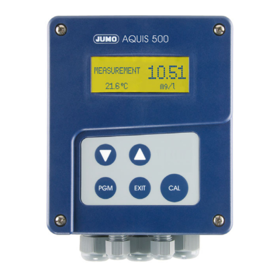
- Page 1 JUMO AQUIS 500 RS Display unit/controller for digital sensors with Modbus protocol Type 202569 B 202569.0 Operating Manual V3.00/EN/00598864...
- Page 2 WARNING! A sudden malfunction of the device, or one of the sensors connected to it, could potentially result in dangerous, imprecise dosing! Suitable preventive measures to stop this happening must be in place. NOTE! Please read these operating instructions before commissioning the device. Keep the manual in a place which is accessible to all users at all times.
-
Page 3: Table Of Contents
Contents Typographical conventions ............5 Warning symbols ..................5 Note symbols ....................5 Description ................6 Identifying the device ............... 8 Nameplate ....................8 Order details ....................9 Accessories (in scope of delivery) ..............10 Accessories (optional) ................10 Mounting .................. 11 General information ..................11 Surface mounting ..................11 Pipe-mounted kit / weather protection canopy .........12 DIN-rail mounting kit ..................12 Mounting in a panel ..................13... - Page 4 Contents Startup ..................40 Quick introduction ..................40 Examples of settings ..................41 Calibrating sensors ..............56 Calibrating sensor type 202613/..............56 Calibrating sensor type 20263x ..............63 Calibrating sensor type 202670/..............69 Setup program ................ 74 Function .....................74 Overcoming errors and malfunctions ........75 Technical data .................
-
Page 5: Typographical Conventions
1 Typographical conventions Warning symbols DANGER! This symbol indicates that personal injury from electrocution may occur if the appropriate precautionary measures are not taken. WARNING! This symbol in connection with the signal word indicates that personal injury may occur if the appropriate precautionary measures are not taken. CAUTION! This symbol in connection with the signal word indicates that damage to assets or data loss will occur if the appropriate precautionary measures are... -
Page 6: Description
2 Description General infor- The device has a total of 1 digital interface, 1 analog temperature input, and 1 mation binary input. The digital interface is suitable for connecting sensors that have a Modbus-RS485 interface. If the connected sensor does not have an integrated temperature sensor, an RTD temperature probe Pt100, Pt1000, or NTC/PTC (up to 4 kΩ) can be connected to the analog temperature input. - Page 7 2 Description Block diagram...
-
Page 8: Identifying The Device
3 Identifying the device Nameplate Position The nameplate is affixed to the right-hand side of the case. JUMO AQUIS 500 RS TN: 00602276 Fulda, Germany Typ: 20256 / 0- 9 2 654 888 000 310 000- 3 2 /000 www.jumo.net F-Nr.: 0168122901016010001... -
Page 9: Order Details
3 Identifying the device Order details (1) Basic type 202569 JUMO AQUIS 500 RS Display unit/controller for digital sensors with Modbus protocol (2) Basic type extension For panel installation Surface-mounted case (3) Input RS422/485 Modbus master (4) Output 1 (for main value or continuous controller) -
Page 10: Accessories (In Scope Of Delivery)
The JUMO AQUIS 500 can be fitted to a pipe (such as a support pillar or rail) with the pipe mounted kit. The JUMO AQUIS 500 can be fitted to a DIN-rail of 35 mm × 7.5 mm (acc. to DIN EN 60715 A.1) with the DIN-rail mounting kit. -
Page 11: Mounting
4 Mounting General information Mounting site Ensure that the device is easily accessible for later calibration. It must be mounted securely and with minimum exposure to vibration. Avoid direct sunlight! Admissible ambient temperature at installation location: -10 to 55 °C at max. 95 % rel. -
Page 12: Pipe-Mounted Kit / Weather Protection Canopy
The pipe-mounted kit for the JUMO AQUIS 500 (part no.: 00483664) can be used to mount the device (and, if applicable, the protective roof for the JUMO AQUIS 500, part no.: 00398161) on pipes or rails with a diameter of 30 to 50 mm. -
Page 13: Mounting In A Panel
4 Mounting Mounting in a panel NOTE! For drilling template, see chapter 12.5 "Template for panel cut-out", page 98. To achieve the specified protection type of IP65, the panel must have the cor- rect thickness. Make the panel cut-out and holes according to the drilling template. Place the control panel (1) with gasket (2) in the panel cut-out and fasten it with screws (2) spacing rollers (4) and nuts (5). - Page 14 4 Mounting Make the electrical connection. Break off the required flap(s) (3) from the cable cover (2) so that the cable can be laid in the cable path. Attach the cable cover (2) onto the control panel (1). Depth behind panel...
-
Page 15: Installation
5 Installation Installation notes DANGER! The electrical connection must only be carried out by qualified personnel. The choice of cable, the installation and the electrical connection must conform to the requirements of VDE 0100 “Regulations on the Installation of Power Circuits with Nominal Voltages below 1000 V” or the appropriate local regulations. -
Page 16: Galvanic Isolation
5 Installation Galvanic isolation not for protective extra-low voltage of voltage supply 30 (DC 12 to 24 V) -
Page 17: Opening And Closing The Device
5 Installation Opening and closing the device Opening the Prior to opening, loosen all cable fittings (2) so that the cables are device moveable. Push connection cable a little into the case so that enough cable reserve is available for opening. Loosen the 4 front-panel screws (1) of the case lid and pull them out as much as possible. -
Page 18: Connecting The Cables
5 Installation Connecting the cables The electrical connection for the surface-mountable housing is easily accessible when the device is folded out. The device contains a guide plate that ensures an optimum cable path. After laying the cables, the cable cover (1) must be attached until it clicks, like shown above. -
Page 19: Terminal Assignment
5 Installation Interior view figure without cable cover and without sensor cable (L-) (L+) 11 12 13 14 15 11 12 13 14 15 16 Lead the connecting cables in through the cable fittings. Use the cable clip (3) to clamp the signal cable to the shielding. The clip (3) must only be attached by a 3.5 x 6.5 pan head screw! If the screw is any longer, dangerous voltage could be directed to the cable shielding! Break off the required flap(s) from the cable cover so that the cable can be... -
Page 20: Pin Configuration
5 Installation Pin configuration Connection Terminal Voltage supply for transmitter/controller Voltage supply (23): 1 N (L-) AC 110 to 240 V; -15/+10 %; 48 to 63 Hz 2 L1 (L+) Voltage supply (25): AC/DC 20 to 30 V; 48 to 63 Hz Voltage supply (30): DC 12 to 24 V;... - Page 21 5 Installation Connection Terminal RTD temperature probe in 3-wire circuit Binary input Outputs Analog output 1 13 + 14 - 0 to 20 mA or 20 to 0 mA or 4 to 20 mA or 20 to 4 mA 0 to 10 V or 10 to 0 V (galvanically isolated) Analog output 2 15 +...
-
Page 22: Operation
6 Operation NOTE! For operation of the device using the optional setup program, see chapter 9 "Setup program", page 74. This section describes how to operate the device using the keypad. Control elements Display Background lighting (during operation) Start calibration Cancel entry / exit level Change level Scroll through selection... -
Page 23: Display
6 Operation Display 6.2.1 Measuring mode (normal display) Example (10) (11) Relay K1 is active Measured value Relay K2 is active Unit of measured value Binary input 1 is Medium temperature controlled (10) Device status e.g. Keypad is locked - Measuring (normal) - Status of calibration Device status (notes) - Alarm (e.g. -
Page 24: Operating Principle
6 Operation Operating principle 6.3.1 Operation in levels see chapter 6.4 "Measurement mode", page 25 see chapter 6.7 "Administrator level", page 27 see chapter 6.5.1 "Min./max. values", page 25 see chapter 6.7.2 "Parameter level", page 29 see chapter 6.5.2 "Output level display", page 26 see chapter 6.7.3 "Enable level", page 29 see chapter 6.10.4 "MANUAL/simulation overview", see chapter 6.7.4 "Basic settings", page 32... -
Page 25: Measurement Mode
6 Operation Measurement mode 6.4.1 Normal display Display The following items are displayed in measurement mode: • Signal of digital interface • Unit (configurable mg/l, ppm, % Sat., etc.) • Temperature of medium MEASURING -> measurement mode 23.7 °C -> temperature of medium 1.58 ppm ->... - Page 26 6 Operation NOTE! The extremes of the main measurands and temperature are not assigned to each other (e.g. not 1.16 ppm at 15.3 °C). To return to measurement mode: Press the key or wait for timeout. Measurements with overrange are ignored. Press the button again briefly to go to the "output level"...
-
Page 27: Operator Level
6 Operation Operator level All parameters that have been approved by the administrator (see chapter 6.7 "Administrator level", page 27) can be edited in this level. All other parameters (indicated by a key ) can only be read. Press the key for more than 2 seconds. - Page 28 6 Operation 6.7.1 Levels of the administrator level Timeout and return to mea- surement mode from all menu items after 60 s Not available for freely configurable sensor.. 1 Only available for freely configurable sensor. Only available for sensors type 202613/... and 202670/...
- Page 29 6 Operation 6.7.2 Parameter level The same settings can be made here as in the operator level – see chapter 6.6 "Operator level", page 27. As the operator has administrator rights here, he/she can also change param- eters that are locked in the operator level. 6.7.3 Enable level In this level, all parameters can be enabled (changes possible) or locked (changes not possible) for editing in the operator level.
- Page 30 6 Operation CONTROLLER CHANNEL 1 or CONTROLLER CHANNEL 2 CONTROLLER TYPE SETPOINT SETPOINT 2 MIN/MAX CONTACT PROPORTIONAL BAND RESET TIME DERIVATIVE TIME PULSE PERIOD ACTR.STROKE TIME HYSTERESIS MIN. ON TIME MAX. PULSE FREQ. OUTPUT LEVEL LIMIT PULL-IN DELAY DROP-OUT DELAY CONTROLLER ALARM ALARM TOLERANCE ALARM DELAY...
- Page 31 6 Operation IN HOLD MODE SAFETY VALUE SIMULATION SIMULATION VALUE DISPLAY LANGUAGE LIGHTING LCD INVERSE MEAS. DISPLAY TYPE LOWER DISPLAY UPPER DISPLAY BAR GR. SCALE START BAR GR. SCALE END MIN/MAX RESET OP. TIMEOUT CONTRAST WASHTIMER CLEANING INTERVAL CLEANING DURATION...
- Page 32 6 Operation 6.7.4 Basic settings To make it easier for users to configure a digital sensor with Modbus protocol and prevent configuration conflicts, the JUMO AQUIS 500 RS has a basic setup wizard. To access the basic settings: ADMINISTR. LEVEL > PASSWORD > BASIC SETTINGS.
-
Page 33: Device Info
6 Operation 6.7.8 Deleting the logbook The five most recent calibration procedures are archived in the calibration log- book. If necessary, the logbook can be deleted following a security prompt. 6.7.9 Resetting the sensor calibrations In case a calibration procedure yields impermissible values, this function restores the factory calibration of the sensors of type 202613/... -
Page 34: Controller Functions
Controller functions Simple switching functions In the JUMO AQUIS 500, simple switching functions such as alarm contact, limit value monitoring, or calibration timer signaling are configured in the parameter level using the "Switching output 1" or "Switching output 2" para- meters. -
Page 35: Manual Mode / Simulation Mode
6.10.1 MANUAL mode using "higher order control functions" Higher order switching functions The JUMO AQUIS 500 is configured to higher order controller functions if the following settings are made: OPERATOR LEVEL > CTRL. CHAN. 1 OR 2 > CONTROLLER TYPE: LIMIT or PULSE WIDTH or PULSE FREQ. - Page 36 To exit HOLD mode, press the keys again for more than 3 seconds. The JUMO AQUIS 500 is no longer in control. The output level at the output of the controller channel is 0 %. To select controller channel 1, use the key;...
- Page 37 6 Operation Output level of controller channels It is possible to display the output levels of the controllers in manual mode in the output level overview. Requirement: the device is in measurement mode. Press the key several times for less than 2 seconds (number varies according to the features and configuration of the device).
- Page 38 ADMINISTR. LEVEL > PASSWORD > PARAMETER LEVEL > SWITCH OUTPUT 1 OR 2/MANUAL MODE: set NO SIMUL. No simulation = No MANUAL mode; the JUMO AQUIS 500 is in control. 6.10.3 Simulation of analog outputs using MANUAL mode Enabling and...
-
Page 39: Hold Mode
6 Operation NOTE! To return to measurement mode: Press the key or wait for timeout. 6.11 HOLD mode In HOLD state, the outputs take the states programmed in the corresponding parameters (controller channel, switching output, analog output). This function can be used to "hold" the switching outputs and the analog out- puts of the device, which means that the current state of the output is main- tained even if the measured value changes. -
Page 40: Startup
7 Startup Quick introduction NOTE! The suggestion below can be used to configure the device quickly and reliably. Mount the device – See chapter 4 "Mounting", page 11. Install the device – See chapter 5 "Installation", page 15 ff. Call up the administrator level (ADMINISTR. LEVEL). Enter the password 300. -
Page 41: Examples Of Settings
Dissolved oxygen 0(4) to 20 mA or 0 to 10 V Galvanically isolated Option: Temperature output 0(4) to 20 mA or 0 to 10 V Galvanically isolated JUMO AQUIS 500 RS JUMO ecoLine O-DO (sensor for dissolved oxygen), type 202613/... - Page 42 Row 2, terminal 2 Green RS485 - Row 2, terminal 3 White RS485 + Row 2, terminal 4 Terminal block 1 Terminal block 2 4-wire connection cable (fixed cable on the sensor) JUMO ecoLine O-DO (sensor for dissolved oxygen), type 202613/...
- Page 43 "AUTOMATIC CONFIG. OF THE SEN- SOR" with "YES" (flashing). Confirm with the key. The JUMO AQUIS 500 now scans the Modbus RS485 interface. If it is con- nected correctly, the following display appears after a short time: Confirm with the key.
- Page 44 7 Startup Implementing the basic settings Use the keys to enter the value for "SALINITY" and confirm with key. Enter the values for "AIR PRESSURE", "UNIT" (select "mg/l"), and "SAM- PLING RATE" using the keys and confirm each using the key.
- Page 45 7 Startup In case of fault: As required In hold mode: As required Safety value: As required Simulation: As required Simulation value: As required Analog output 2 Signal selector: Temperature Signal type: 4 to 20 mA Scaling start: 0 °C Scaling end: 50 °C For calibration:...
- Page 46 Chlorine concentration 0(4)...20 mA or 0...10 V, galvanically isolated Option: Temperature output 0(4)...20 mA or 0...10 V, galvanically isolated JUMO AQUIS 500 RS JUMO tecLine Cl2 (sensor for free chlorine), type 202630/50... or /51... Individual fitting flow monitor, part no.: 00605507...
- Page 47 Row 2, terminal 12 (NPN N/O contact) Blue Row 1, terminal 12 Terminal block1 Terminal block 2 Sensor connection cable, part no. 00638337 (5 m) JUMO tecLine Cl2 (sensor for free chlorine), type 202630/50 or /51... JUMO individual fitting flow monitor, type 202811/10...
- Page 48 "AUTOMATIC CONFIG. OF THE SEN- SOR" with "YES" (flashing). Confirm with the key. The JUMO AQUIS 500 now scans the Modbus RS485 interface. If it is con- nected correctly, the following display appears after a short time: Confirm with the key.
- Page 49 7 Startup Implement the basic settings Use the keys to enter the value for „UNIT“ („ppm“ in this example) and confirm with the key. Enter the value for the decimal point of the main value („DEC. POINT MAIN VAL.“) using the keys („X.xxx“...
- Page 50 7 Startup Simulation: As needed Simulation value: As needed Analogausgang 2 Signal selector: Temperature Signal type: 4 ... 20 mA Scaling start: 0 °C Scaling end: 50 °C During calibration: As needed On error: As needed In hold mode: As needed Safe value: As needed Simulation:...
- Page 51 Main output value Turbidity 0(4) to 20 mA or 0 to 10 V Galvanically isolated Option: Temperature output 0(4) to 20 mA or 0 to 10 V Galvanically isolated JUMO AQUIS 500 RS JUMO ecoLine NTU (sensor for turbidity measurements), type 202670/...
- Page 52 Row 2, terminal 2 Green RS485 - Row 2, terminal 3 White RS485 + Row 2, terminal 4 Terminal block 1 Terminal block 2 4-wire connection cable (fixed cable on the sensor) JUMO ecoLine NTU (sensor for turbidity measurements), type 202670/...
- Page 53 "AUTOMATIC CONFIG. OF THE SEN- SOR" with "YES" (flashing). Confirm with the key. The JUMO AQUIS 500 now scans the Modbus RS485 interface. If it is con- nected correctly, the following display appears after a short time: Confirm with the key.
- Page 54 7 Startup Implementing the basic settings Use the keys to select the measuring range "0 to 200" and con- firm with the key. Use the keys to select the "NTU" unit for the display and confirm with the key. For the "TEMPERATURE SENSOR" request, select "MODBUS" and con- firm with the key.
- Page 55 7 Startup In case of fault: As required In hold mode: As required Safety value: As required Simulation: As required Simulation value: As required Display Language: As required Lighting: As required LCD inversion: As required Measured value display type: As required Display on bottom: As required Display on top:...
-
Page 56: Calibrating Sensors
Its measuring method, accredited according to ASTM D888-05 is based on the principle of lumines- cence quenching. As with all optical sensors, the JUMO ecoLine O-DO is sub- ject to sensor aging and sensor drift during operation. The effects of these fac- tors are compensated for by calibration. - Page 57 8 Calibrating sensors 8.1.2 End value calibration Prerequisite • The device must be supplied with voltage – see chapter 5 "Installation", page 15 ff. • The sensor must be connected • Sensor startup must be complete • Calibration must be enabled – see chapter 6.7 "Administrator level", page •...
- Page 58 8 Calibrating sensors NOTE! Water vapor-saturated air occurs, for example, directly above the water sur- face in a half-full glass of water at room temperature. Make sure there are no drops of water on the bottom of the membrane. The sensor must stay dry during the measurement.
- Page 59 8 Calibrating sensors 8.1.3 Two-point calibration Prerequisite • The device must be supplied with voltage (see chapter 5 "Installation", page 15 ff). • The sensor must be connected. • Sensor startup must be complete. • Calibration must be enabled (see chapter 6.7 "Administrator level", page 27).
- Page 60 8 Calibrating sensors CAUTION! Do not leave the sensor in contact with the sodium sulfite solution for more than 1 hour. NOTE! For flawless measurement, make sure that there are no air bubbles on the bottom of the membrane of the submerged sensor. Wait until the displayed value is stable at "0.00%Sat"...
- Page 61 8 Calibrating sensors Confirm with the key. The zero point and slope determined by the device (deviation from the factory calibration) are displayed along with the corrected measured value, which should now be 100.0 % Sat. Use the key to apply the calibration or the key to reject the calibra- tion.
- Page 62 8 Calibrating sensors 8.1.4 Calibration logbook The data records for the last 10 successful calibrations are saved in the con- nected sensor, are extracted by the JUMO AQUIS 500 RS, and can be viewed in the calibration logbook. Accessing the calibration logbook The device is in measurement mode.
-
Page 63: Calibrating Sensor Type 20263X
(Type 202636/...) peracetic acid Calibrating methods The JUMO AQUIS 500 RS provides two calibration methods for the JUMO tecLine 20263x type sensors: • For end value calibration (typical method), the slope of the sensor is cali- brated, see chapter 8.2.2 "End value calibration", page 64. - Page 64 8 Calibrating sensors 8.2.2 End value calibration Prerequisite • The device must be supplied with voltage – see chapter 5 "Installation", page 15 ff. • The sensor must be connected • Sensor startup must be complete • Calibration must be enabled – see chapter 6.7 "Administrator level", page •...
- Page 65 8 Calibrating sensors Calibration for the desired chlorine concentration (final value) Bring the process to the defined chlorine concentration state. Immerse the sensor into the process solution. Determine the chlorine concentration of the process solution by using the DPD-1 method. When the displayed value is stable, confirm with the key.
- Page 66 8 Calibrating sensors 8.2.3 Two-point calibration Prerequisite • The device must be supplied with voltage – see chapter 5 "Installation", page 15 ff. • The sensor must be connected • Sensor startup must be complete • Calibration must be enabled – see chapter 6.7 "Administrator level", page •...
- Page 67 8 Calibrating sensors Calibrating the zero point Immerse the sensor into chlorine-free process water. When the display value is stable around the zero point, confirm with key. The display changes for the measurement of the reference value. Calibrating the reference value Bring the process to the defined chlorine concentration state.
- Page 68 The device returns to measurement mode. 8.2.4 Calibration logbook The data records for the last 5 successful calibrations are saved in the con- nected sensor, are extracted by the JUMO AQUIS 500 RS, and can be viewed in the calibration logbook. Accessing the calibration logbook The device is in measurement mode.
-
Page 69: Calibrating Sensor Type 202670
90° scat- tered light method. As with all optical sensors, the JUMO ecoLine NTU is sub- ject to sensor aging and sensor drift during operation. The effects of these fac- tors are compensated for by calibration. - Page 70 8 Calibrating sensors 8.3.2 Two-point calibration Prerequisite • The device must be supplied with voltage (see chapter 5 "Installation", page 15 ff). • The sensor must be connected. • Sensor startup must be complete. • Calibration must be enabled (see chapter 6.7 "Administrator level", page 27).
- Page 71 8 Calibrating sensors Calibrating the zero point Bring the sensor to the defined state 0 NTU by submersing it in distilled water. To avoid measuring errors, the distance to the vessel wall must not be below the minimum distance of 20 mm. NOTE! For flawless measurements, make sure that there are no air bubbles on the optics of the submerged sensor.
- Page 72 8 Calibrating sensors ing errors, the distance to the vessel wall must not be below the minimum distance of 20 mm. The device suggests the reference value "100.0 NTU" (flashing) for the calibra- tion of the measuring range (0 to 200 NTU) selected in this example. Set the exact reference value (in this example 112.0 NTU) using the keys.
- Page 73 8 Calibrating sensors 8.3.3 Calibration logbook The data records for the last 10 successful calibrations are saved in the con- nected sensor, are extracted by the JUMO AQUIS 500 RS, and can be viewed in the calibration logbook. Accessing the calibration logbook The device is in measurement mode.
-
Page 74: Setup Program
Data transfer from or to the transmitter can only take place if it is supplied with voltage – See chapter 5 "Installation", page 15 ff. Connection JUMO AQUIS 500 RS PC interface cable with USB/TTL converter, part no.: 00456352 PC or notebook... -
Page 75: Overcoming Errors And Malfunctions
10 Overcoming errors and malfunctions Problem Possible causes Measures No measured value dis- No voltage supply Check voltage supply play or no current output Measured value display Sensor not submerged Top up container 0000 or in medium current output 4 mA Container level too low Flow fitting blocked Clean flow fitting... - Page 76 202613/...) The sensor has indicated a fault to Perform calibration the JUMO AQUIS 500; sensor is not operating within its specified measuring range 1.Ex factory, the device is pre-configured for the connection of a type 202613/... sensor. If e.g. a type 202670/ ...
-
Page 77: Technical Data
Can be changed to °F. Depending on the supporting points. 11.3 Sampling rate Analog Digital interface Digital interface Digital interface Digital interface temperature input with JUMO with JUMO with JUMO with freely config- ecoLine O-DO tecLine 20263x ecoLine NTU urable sensor 500 ms Adjustable,... -
Page 78: Analog Outputs (Maximum 2)
11 Technical data 11.7 Analog outputs (maximum 2) Output type Signal range Accuracy Temperature Admissible influence load resistance ≤ 0.25 % ≤ 500 Ω Current signal 0(4) to 20 mA 0.08 %/10 K ≤ 0.25 % ≥ 500 Ω Voltage signal 0 to 10 V 0.08 %/10 K The analog outputs behave according the NAMUR NE43 recommendation. -
Page 79: Display
11 Technical data 11.12 Display LCD display 120 × 32 pixels Background lighting Programmable: • Off • 60 seconds "ON" during operation 11.13 Case Material Cable inlet Cable glands, max. 3× M16 and 2× M12 Special feature Ventilation element for prevent of condensation (on IP 67 surface-mounted case version) Ambient temperature range -10 to +50 °C (accuracy figures are adhered to in this range) -
Page 80: Appendix
12 Appendix 12.1 Operator level parameters If a large number of device parameters are to be configured, it is advisable to make a note of all the parameters to be changed in the following table and to work through the parameters in the order specified. NOTE! The following list shows the maximum number of changeable parameters. - Page 81 12 Appendix Parameter Selection/value range per default setting Main value unit None (only for freely configurable ‰ sensor) %Sat µg/l mg/l µs/cm ms/cm kΩ MΩ µA Customer-specific Uncompensated main None value unit ‰ (only for freely configurable sensor) %Sat µg/l mg/l µs/cm ms/cm...
- Page 82 12 Appendix Parameter Selection/value range per default setting Measurand for sensor Free chlorine type 20263x/... Total chlorine Ozone Hydrogen peroxide Peracetic acid Unit for sensor type 20263x/... mg/l µg/l ‰ Temperature compensa- Internal tion source External Salinity 0 to 100 g/kg Air pressure 500 to 1013 to 1500 hPa Sampling rate...
- Page 83 12 Appendix Parameter Selection/value range per default setting Min./max. contact Min. contact (falling/rising Max. contact characteristic line) Proportional band 0 to 9999 (decimal places configurable) Reset time 0 to 9999 Derivative time 0 to 9999 Pulse period 2.5 to 20 to 999.5 Actuator time 15 to 60 to 3000 s (only for three-step control-...
- Page 84 12 Appendix Parameter Selection/value range per default setting Pulse period 2.5 to 20 to 999.5 Actuator time 15 to 60 to 3000 s (only for three-step control- ler for controller 1) Hysteresis 0 to 200 to 9999 (decimal places configurable) (of limit value controller) Minimum start time 0.5 to 999.5...
- Page 85 12 Appendix Parameter Selection/value range per default setting Switching output 1 Function No function Controller output 1 Controller output 2 Controller alarm 1 Controller alarm 2 Controller alarm AF1 main value AF2 main value AF7 main value AF8 main value AF1 temperature AF2 temperature AF7 temperature...
- Page 86 12 Appendix Parameter Selection/value range per default setting Switching output 2 Function No function Controller output 1 Controller output 2 Controller alarm 1 Controller alarm 2 Controller alarm AF1 main value AF2 main value AF7 main value AF8 main value AF1 temperature AF2 temperature AF7 temperature...
- Page 87 12 Appendix Parameter Selection/value range per default setting Analog output 1 Signal selector Actual value for main value / temperature Continuous controller output 1 Continuous controller output 2 Signal type 0 to 10 V 0 to 20 mA 4 to 20 mA 10 to 0 V 20 to 0 mA 20 to 4 mA...
- Page 88 12 Appendix Parameter Selection/value range per default setting Response in case of error Low (0 V/0 mA/3.4 mA) High (10.7 V/22 mA) Frozen Safe value Response in hold mode Low (0 V/0 mA/3.4 mA) High (10.7 V/22 mA) Frozen Safe value Moving Safety value 0 to 10.7 V...
-
Page 89: Parameter Explanation
12 Appendix 12.2 Parameter explanation FUNCTION NO FUNCT. Alarm window AF1 MAIN VALUE Alarm window AF2 MAIN VALUE Limit value controller AF7 MAIN VALUE Limit value controller AF8 MAIN VALUE Alarm window AF1 TEMPERAT. Alarm window AF2 TEMPERAT. Limit value controller AF7 TEMPERAT. Limit value controller AF8 TEMPERAT SENSOR ERROR CALIB. - Page 90 12 Appendix Trigger condition Trigger condition Pulse contact Pulse contact Alarm pulse contact Alarm pulse contact Trigger condition longer than Trigger condition shorter than pulse duration pulse duration Time Pulse duration Spacing Setpoint value / limit value HySt Hysteresis Actual value / measured value MEAS.
- Page 91 12 Appendix Rising Falling Stable Sharp Medium Slight Slight Medium Sharp NOTE! The measured value trend is calculated from the last 10 measured values. At a sampling rate of 10 s, the last 100 seconds are taken into account. BAR GRAPH •...
- Page 92 12 Appendix DISPLAY ON BOTTOM NOTE! The "DISPLAY ON BOTTOM" and "DISPLAY ON TOP" parameters are only available for the "NORMAL" or "TREND" measured value display types, but not for the "BAR GRAPH" measured value display type. Operation mode Display on bottom Display on top The "bottom"...
-
Page 93: Term Definition
12 Appendix 12.3 Term definition Pulse length controller (output active when x > w and control structure P) 100% Switching period Process value X Proportional band X X - W Setpoint W If the actual value x exceeds the setpoint value w, the P-controller controls in proportion to the control deviation. - Page 94 12 Appendix Customer-specific table In this mode, you can use the optionally available setup program (no entry can be made on the device) to create a customer-specific characteristic line in the form of a table with up to 20 pairs of resistance/temperature values for the analog temperature input.
-
Page 95: Flow Diagram Of The Basic Setting Wizard
12 Appendix 12.4 Flow diagram of the basic setting wizard 12.4.1 Automatic configuration of a sensor Start of the basic setup wizard configure sensor automatically sensor found type 202670 type 202670 type 202613 type 202613 type 20263x type 20263x measuring range, salinity, unit, unit,... - Page 96 12 Appendix 12.4.2 Manual configuration of a sensor temperature sensor MODBUS PT100/PT1000 NO SENSOR CUSTOMIZED temperature select sensor type type 202670 type 202670 type 202613 type 202613 other other type 20263x type 20263x baud rate, device address, baud rate, parity, salinity, parity measuring range,...
- Page 97 12 Appendix...
-
Page 98: Template For Panel Cut-Out
12 Appendix 12.5 Template for panel cut-out... -
Page 99: Index
13 Index Accessories Electrical connection Administrator level Flow monitor Analog output Type 202613/... Type 20263x/50... or /51... Type 202670/... Enable level Basic settings Example setting Binary input Measuring dissolved oxygen Block diagram Measuring free chlorine Turbidity measurement Examples of settings Cable routing CAL key Calib. - Page 100 13 Index Opening the device Operating principle Operator Operator level operator level parameters Order details Output Output level display Outputs Overcoming errors and malfunctions – Overrange Panel installation Parameter explanation Parameter level Parameter table Password Pin configuration Pipe mounting Pulse frequency controller Pulse length controller Quick introduction Resetting the sensor calibrations...
- Page 102 JUMO GmbH & Co. KG JUMO Instrument Co. Ltd. JUMO Process Control, Inc. Street address: JUMO House 6733 Myers Road Moritz-Juchheim-Straße 1 Temple Bank, Riverway East Syracuse, NY 13057, USA 36039 Fulda, Germany Harlow, Essex CM 20 2DY, UK Phone:...
Need help?
Do you have a question about the AQUIS 500 RS and is the answer not in the manual?
Questions and answers