JUMO IMAGO 500 Operating Manual
Multi-channel process and program controller
Hide thumbs
Also See for IMAGO 500:
- Manual (13 pages) ,
- Interface description (40 pages) ,
- Operating manual (92 pages)

Related Manuals for JUMO IMAGO 500


Summary of Contents for JUMO IMAGO 500
- Page 1 JUMO IMAGO 500 Multi-channel Process and Program Controller Operating Manual 70359000T90Z001K000 V2.01/EN/00403546...
- Page 2 Please read these Operating Manual before starting up the instrument. Keep these operating manual in a place which is accessible to all users at all times. These operating manual are valid from software version 162.03.05. Please assist us to improve these operating manual, where necessary. Your suggestions will be welcome.
-
Page 3: Table Of Contents
Contents Introduction Description ....................5 Typographical conventions ................. 6 Identifying the instrument version Type designation ..................7 Accessories ....................8 Nameplate ..................... 9 Mounting Location and climatic conditions .............. 11 Dimensions ....................11 Fitting ......................12 Cleaning the front panel ................12 Electrical connection Installation notes .................. - Page 4 Contents Parameterization Configuration Analog inputs ....................41 Controller ....................46 Generator ....................49 Limit comparators ..................53 Outputs ......................56 Logic functions ................... 58 Math and logic module ................63 C-level control .................... 65 7.8.1 C-level control example ................66 Display ......................
-
Page 5: Introduction
1 Introduction 1.1 Description Type 703590 is a process and program controller with up to eight controller channels or four program channels. The instrument is built to the format 144 mm × 130 mm for a standard 92 mm × 92 mm panel cut-out and a mounting depth of 170 mm. -
Page 6: Typographical Conventions
1 Introduction 1.2 Typographical conventions Warning Danger This symbol is used when there may be danger to signs personnel if the instructions are ignored or not followed correctly! Caution This symbol is used when there may be damage to equipment or data if the instructions are ignored or not followed correctly! Caution... -
Page 7: Identifying The Instrument Version
2 Identifying the instrument version 2.1 Type designation Basic type 703590 Type 703590: Process snd program controller Basic type extensions No. of controller and program channels 2 controller channels with max. 2 program channels 4 controller channels with max. 4 program channels 8 controller channels with max. -
Page 8: Accessories
2 Identifying the instrument version 2.2 Accessories External relay One of the RS422/485 interfaces is required to module operate one or two external relay modules 242 243 442 443 142 143 342 343 3 2 3 3 (L+) (L-) (external relay or logic outputs). Power Versions: Voltage supply AC 110 to 240 V... -
Page 9: Nameplate
2 Identifying the instrument version PC evaluation PCC+PCA (software) software ® under Windows XP, Vista, 7 (32-bit and 64-bit) 2.3 Nameplate Position The nameplate is glued onto the instrument. Contents It carries important infomation, for instance: Description Designation Example nameplate Instrument type 703590/281-8800-350000-23-00/000 Part no. - Page 10 2 Identifying the instrument version...
-
Page 11: Mounting
3 Mounting 3.1 Location and climatic conditions The conditions at the location must meet the requirements specified in the Technical Data. The ambient temperature at the location can be -5 to +50 °C, with a relative humidity of not more than 75 %. 3.2 Dimensions Close mounting Minimum spacing of panel cut-outs... -
Page 12: Fitting
3 Mounting 3.3 Fitting h From the back, fit the seal that is supplied onto the instrument. h Insert the instrument from the front into the panel cut-out. h From behind the panel, slide the mounting brackets into the guides on the sides of the housing. -
Page 13: Electrical Connection
4 Electrical connection 4.1 Installation notes • The choice of cable, the installation and the electrical connection must con- form to the requirements of VDE 0100 “Regulations on the Installation of Power Circuits with Nominal Voltages below 1000 V” or the appropriate local regulations. -
Page 14: Electrical Isolation
4 Electrical connection • Since the instrument is short-circuit proof only to a limited extent, an exter- nal fusing and a switch-off facility must be provided. Depending on the sup- ply voltage, the following values apply to the external fusing: AC/DC 20 to 53 V, 48 to 63 Hz fuse 4 A slow (only for operation in SELV or PELV current circuits) -
Page 15: Connection Diagram
4 Electrical connection 4.3 Connection diagram OUT 1 / IN 5 OUT 2 / IN 6 OUT 3 / IN 7 The electrical connection must only be carried out by qualified personnel. COM 1 29-32 OUT 4 / IN 8 OUT 5 OUT 6 COM 2... - Page 16 4 Electrical connection Outputs (slots: OUT1to 6) 1 analog 1 logic output 1 solid-state relay 2 logic outputs 1 changeover 2 make output 0/22 V * 1 A / 230 V 0/14 V Ö 0/4 to 20 mA 0/2 to 10 V * or supply for two-wire transmitter Slot Plug-in pcb with...
-
Page 17: Operation
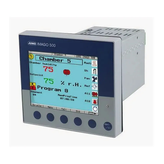
5 Operation 5.1 Operation: General 5.1.1 Displays and controls Front view (10) EXIT Displays and No. Meaning controls Status line with time, date, name of screen template and instrument name. Color screen (screen templates can be configured) Factory setting for fixed-setpoint controller: process value, setpoint, output level (bar graph). - Page 18 5 Operation Symbols in Symbol Bedeutung display Info Alarm is present Alarm messages must be acknowledged (see explanation for “screen operating loop”) Automatic mode/Program is running Manual (“Hand”) operating mode Enables setpoint and control contact definition in the case of a program controller.
-
Page 19: Overview Of Operation
5 Operation 5.1.2 Overview of operation Custom picture 2 Custom picture 1 Recording Collective picture 2 Collective picture 1 Channel 8 Channel 1 v Chapter 7.9 “Display” Event list Service mode Device info Configuration level Parameter level Operating level Program start menu User level Program editor for program controller/... - Page 20 5 Operation Screen The operating loop contains the screen templates for a maximum of four con- operating loop troller channels, the collective picture of all the active controller channels, the recording function as well as two freely definable screen templates. The screen templates can be individually switched into display.
- Page 21 5 Operation Menu Event list Service mode Device info Configuration level Parameter level Operating level User level EXIT User level With the help of this screen template, the user can compile parameters that have to be frequently altered, through the setup program. This screen template is only displayed when appropriately configured.
-
Page 22: Entering Values And Selecting Settings
5 Operation 5.1.3 Entering values and selecting settings Entering values Parameters can be altered in a number of screen templates. h Select parameter h Increase parameter value with h Decrease parameter value with The longer the key is pressed the faster the value changes. Approx. 2sec after releasing the key, the entry will be automatically accepted. -
Page 23: Setpoint Input
5 Operation 5.1.4 Setpoint input Configuration Each controller channel has four setpoints which can be switched by logic sig- in controller nals. Setpoints for the controller are defined as shown below. Exception: configuration of a program controller with external setpoint input. In this case, setpoint 2 corresponds to the program setpoint. -
Page 24: Recording
5 Operation 5.1.5 Recording Screen The recording function can be used to show the traces of up to four analog template signals and the switching actions of up to three logic signals. Momentary values Graphical representation Scaling of the of up to four analog signals of the analog signals analog signals (switchable) -
Page 25: Operation: Controller
5 Operation h Zoom in /zoom out of trace with h Return to the scroll functions with h Quit history with EXIT 5.2 Operation: Controller If the instrument has been configured as a fixed-setpoint controller, the follow- ing actions can be performed in automatic/manual mode: 5.2.1 Altering the setpoint The active setpoint of a controller channel can be altered in the corresponding screen template or at the operating level. -
Page 26: Manual Mode
5 Operation 5.2.2 Manual mode Altering the The control loop of the controller channel that is displayed can be interrupted output by switching to manual mode. h Switch to manual mode with EXIT (hold key down for at least 2 sec!) (the symbol for manual mode appears in the operating mode display) h Alter the output with (the meaning of the softkeys changes, an input window appears) -
Page 27: Program Editor
5 Operation 5.3.1 Program editor h Call up with Input template Edit program h Select program using the cursor keys h Select program channel using the cursor keys Number of program channel Program number and name Number of Entry mode program - edit segments... - Page 28 5 Operation General 50 programs with up to 99 segments each can be programmed; a total of 1000 segments can be implemented. Programs are created by programming setpoints and segment times, segment by segment. Furthermore, the states of the control contacts 1 to 16 and the active parameter set can be defined for each segment.
- Page 29 5 Operation Tolerance band To monitor the process value, a tolerance band can be applied around the set- point profile for each segment. If the upper or lower limit is infringed, a tolerance band signal is generated, which is internally processed or produced via an output. Example: If the process value goes above the set tolerance band, the logic function “Program stop”...
-
Page 30: Starting The Program
5 Operation Entering repeat A group of segments that are arranged in sequence can be repeated up to 99 cycles times or repeated endlessly (input: -1). The repeat cycles are programmed in the last segment of the group. Example: S02 to S04 are to be repeated once. h Edit segment 4 h Set number of repeat cycles to Cy=1 h Set start segment of repeat to No.=2... - Page 31 5 Operation Starting the A program can be started at a specific point of time. There are two program with configurable options: time input 1. Start at a specified date and time 2. Start with a specified start delay in hours, minutes and seconds. v Chapter 7.3 “Generator”...
-
Page 32: Overview Of Operation
5 Operation 5.3.3 Overview of operation The diagram below provides an overview of the different operating modes and operating options of a program controller. Many operating options can also be implemented via the logic functions. Contr. manual mode h Alter output with Only with active controller in the basic status! Basic status... - Page 33 5 Operation Temporary Temporary alterations are alterations to the current program in the program alterations editor. They are not stored in the program memory, i.e. alterations will be lost after a fresh start. In the case of alterations concerning the current segment, the setpoint se- quence is automatically adapted.
-
Page 34: Shifting The Program Profile
5 Operation 5.3.4 Shifting the program profile The function “External setpoint with correction” can be used to shift the pro- gram profile upwards or downwards. External setpoint The external setpoint is defined via an analog signal. v Chapter 7.2 “Controller”... -
Page 35: Parameterization
6 Parameterization General Two parameters sets can be stored for each controller channel. The parameter sets can be switched via the logic function, for example. Access code Factory-set code: 0001 The access code can be modified via the setup program. Parameter level Controller 1 (2 to 8) Parameter set 1 (2) - Page 36 6 Parameterization Controller structure 2 Controller P, I, PD, PI, PID PID The parameters refer to the second controller output for structure 2 a 3-state controller. Proportional 0to9999 digits 0 digits band Derivative time 0 to 9999 sec 80 sec Reset time 0 to 9999 sec 350 sec...
- Page 37 7 Configuration General The following applies to the representation of parameters and functions at the configuration level: The parameter is not displayed or cannot be selected if • the instrument features do not permit the function assigned to the parame- ter.
- Page 38 7 Configuration Analog selector Y cascade C1 Standardized output with cascade control for controller 1 Y cascade C8 Standardized output with cascade control for controller 8 Setpoint 1 C1 Setpoint 1 for controller 1 Setpoint 4 C1 Setpoint 4 for controller 1 Setpoint 1 C2 Setpoint 1 for controller 2 Setpoint 4 C2...
- Page 39 7 Configuration Analog selector RemSegT PCh1 Remaining segment time for program channel 1 (in seconds) RemSegT PCh4 Remaining segment time for program channel 4 (in seconds) Seg. Time PCh1 Segment time for program channel 1 (in seconds) Seg. Time PCh4 Segment time for program channel 4 (in seconds) Progam time Total program time (in seconds)
- Page 40 7 Configuration Binary selector Binary logic value any binary logic value (from address) Program end Program end signal Ramp end 1 Ramp end signal for controller 1 Ramp end 8 Ramp end signal for controller 8 Tolerance band Signal on going above/below tolerance band Manual mode C1 Controller 1 in manual mode / program pause Manual mode C8...
-
Page 41: Configuration Analog Inputs
7 Configuration 7.1 Analog inputs Depending on the instrument version, up to eight analog inputs are available. Configuration The analog inputs are numbered in sequence (IN 1 to 8) according to their slot Analog inputs assignment. Controller Generator Limit comparators Outputs Logic functions Math / Logic... - Page 42 7 Configuration Analog input 1 (2 to 8) Value/selection Description Linearization Linear For customized linearization (e.g. “customized 1”) a maximum of 20 knee-points can be implemented, or a 5th Pt100 order polynominal function programmed (only with setup Pt100 JIS program). Ni100 For the linearization “KTY11-6”, the resistance is 2 k...
- Page 43 7 Configuration Analog input 1 (2 to 8) Value/selection Description Range start -1999 to +9999 The instrument will change over earlier to the response defined for overrange/underrange if the range is restricted. Range end -1999 to +9999 Example: Range: Pt100 -200 to +850 °C. An alarm message is to be generated for temperatures outside the range 15 to 200 °C.
- Page 44 7 Configuration Customized A signal is processed electronically (conversion, linearization …) to produce a recalibration measured value via the analog inputs of the controller. This measured value enters into the computations of the controller and can be visualized on the displays (measured value = displayed value).
- Page 45 7 Configuration Procedure Apply two measurement points ((1), (3)), one after another, to the controller; they should be as far apart as possible. At these measurement points, enter the required display value (start value, end value) in the controller. A reference instrument is most convenient for determi- ning the measured values M1 and M2.
-
Page 46: Controller
7 Configuration 7.2 Controller The following are set here: controller type, input variables of the controller, the Configuration setpoint limits, conditions for manual mode and the presettings for self-optimi- Analog inputs zation of the eight controller channels. Controller Generator Limit comparators Outputs Logic functions Math / Logic... - Page 47 7 Configuration Controller 1 (2 to 8) Configuration Value/selection Description Dead band 0 to 100 The output movement is suppressed within the dead band; e. g. with noisy signals. The dead band is only effective for controller structures with an I-component. External setpoint no correction External setpoint input without correction...
- Page 48 7 Configuration Controller 1 (2 to 8) Inputs Value/selection Description Output feedback (Analog selector) Defines the source for output feedback. Switched off Output feedback must be configured in the case of a continuous controller with integral actuator driver! Additive (Analog selector) Defines the source for the additive disturbance.
-
Page 49: Generator
7 Configuration 7.3 Generator The basic function of the instrument is defined here. The instrument with all Configuration the available controller channels can be operated as fixed-setpoint controller, Analog inputs program controller or program generator. Controller Generator Furthermore, ramp functions (fixed-setpoint controller) can be activated for the Limit comparators individual controller channels and different parameters defined for the program Outputs... - Page 50 7 Configuration The ramp function can be stopped and canceled via the logic functions. v Chapter 7.6 “Logic functions” Ramp Ramp controller 1 (2 to 8) Value/selection Description Function Inactive Defines whether the ramp function is to be activated for the corresponding controller channel.
- Page 51 7 Configuration Program Value/selection Description Response to power Prog.canceled Response of the program run on a power failure failure Continue Standstill Program canceled: Program run canceled; instrument switches to basic status. Continue X% Continue PV Continue: The program continues from the point at which it was canceled at the time of the supply failure.
- Page 52 7 Configuration Program Value/selection Description Start at time Starts the program after an adjustable start delay, or at a time that can be defined (start with time). Setting the clock: v Chapter 7.11 “Device data” Program end time -1 to 0 to 9999 sec Duration of program end signal If a program is ended, the program end signal is switched on for a definable time period and can, for example, be...
-
Page 53: Limit Comparators
7 Configuration 7.4 Limit comparators Limit comparators (limit monitors, limit contacts) can be used to monitor an input variable (limit comparator process value) against a fixed limit or another Configuration variable (limit comparator setpoint). When a limit is exceeded, a signal can be Analog inputs output or an internal controller function initiated. - Page 54 7 Configuration Limit comparator 1 (2to16) Value/selection Value/selection LK function no funct. Limit comparator function LK type 1 LK type 8 Limit value -1999 to 0 to +9999 Limit value to be monitored Switching 0 to 1 to 9999 Switching differential differential Action Absolute...
- Page 55 7 Configuration Absolute At the time of alteration, the limit comparator acts in accordance with its func- tion. Relative The limit comparator is in the OFF status. An alteration of the limit value or the (limit comparator) setpoint could cause the limit comparator to switch ON.
-
Page 56: Outputs
7 Configuration 7.5 Outputs Configuration of the instrument outputs are subdivided into analog outputs Configuration (max. 6) and logic outputs (max. 12). Display and numbering of the outputs de- Analog inputs pends on the assignment of the output slots OUT 1 to 6. Controller Generator Limit comparators... - Page 57 7 Configuration Analog outputs Analog output 1 (2 to 6) Value/selection Description Zero point -1999 to 0 to +9999 A physical output signal is assigned to the value range of an output variable. End value -1999 to 100 to +9999 Example: Setpoint 1 (value range: 150 to 500 °C) is to be output via the analog output (0 to 20 mA).
-
Page 58: Logic Functions
7 Configuration 7.6 Logic functions Functions are assigned here to the logic signals of the logic inputs, limit Configuration comparators and logic functions (formula). Analog inputs Controller In addition, the functions for control contacts, tolerance band signal and pro- Generator gram end signal are defined for program controllers/generators. - Page 59 7 Configuration Combined The functions are implemented through logic functions the combination of up to four control variables. Any control variable can be selected. The states Z1 to Z4 are assigned to the control variables in descending order of the control variables (see list on the right).
- Page 60 7 Configuration Program selection Program Z6 Z5 Z4 Z3 Z2 Z1 Program 1 Program 2 Program 3 Program 4 Program 64 0 = contact open /OFF 1 = contact closed /ON Multifunctional Logic functions can cover several func- logic functions tions simultaneously.
- Page 61 7 Configuration Logic input 1 (2 to 6) Limit comparator 1 (2 to 16) Logic 1 (2 to 16) Control contact 1 (2 to 16) Tolerance band signal Program end signal Ramp end signal 1 (2 to 8) Timer 1 (2 to 4) Value/selection Description Selection of...
- Page 62 7 Configuration Logic input 1 (2 to 6) Limit comparator 1 (2 to 16) Logic 1 (2 to 16) Control contact 1 (2 to 16) Tolerance band signal Program end signal Ramp end signal 1 (2 to 8) Timer 1 (2 to 4) Value/selection Description Synchronize clock...
-
Page 63: Math And Logic Module
7 Configuration 7.7 Math and logic module Special controller types (differential, ratio, humidity, C-level controller) or Configuration mathematical formulae and logical combinations are configured here. Analog inputs Controller C-level control and math/logic formulae (math and logic module) are extras. Generator The results of the calculations can be called up, under the variables “Math X”... - Page 64 7 Configuration Ratio Control is always based on variable a. control The math module forms the ratio of the measurements of a and b (a/b) and produces the setpoint for the controller. The ratio is made available as a value, via the function “Math X”, and can be displayed.
-
Page 65: C-Level Control
7 Configuration 7.8 C-level control C-level control is used for the control of carbon in the atmosphere of a gas Configuration coking furnace. The C-level is determined through the oxygen measurement Analog inputs with a zirconium dioxide sensor and measurement of the sensor temperature. Controller Generator C-level control is an extra. -
Page 66: C-Level Control Example
7 Configuration Value/selection Description Sensor voltage (Analog selector) Source for the voltage signal of the zirconium dioxide sensor Switched off Sensor (Analog selector) Source for the temperature signal of the zirconium dioxide temperature sensor Switched off CO measurement (Analog selector) Source for the measurement signal of the CO content Switched off CO content... -
Page 67: Display
7 Configuration 7.9 Display The time-dependent screen saving is defined here. In addition, time-out and Configuration the sequence of the different screen templates can be defined. The Analog inputs representations on the controller pictures 1 to 8 and on the collective picture Controller can be adapted to suit individual requirements. - Page 68 7 Configuration Value/selection Description Operating loop The screen templates that are to appear in the screen operating loop can be selected. Controller pic. 1 Visible as a factory setting: Controller pic. 8 - Controller pic. 1 Collective pic. 1 - Recording Collective pic 2 Recording Custom pic.
- Page 69 7 Configuration Collective picture Controller 1 (2 to 8) Value/selection Description Value column 1 (Analog selector) Display: Ramp end C1 Decimal point XXXX. column 1 Controller 1 Value column 2 (Analog selector) Controller 2 Setpoint C1 Controller 3 Controller 4 Decimal point XXXX.
-
Page 70: Interfaces
7 Configuration 7.10 Interfaces The interface parameters for the standard RS422/485 interface (MODbus 1) Configuration and an optional RS422/485 (MODbus 2) or PROFIBUS-DP interface have to Analog inputs be configured in order to communicate with PCs, bus systems and peripheral Controller devices. -
Page 71: Device Data
7 Configuration 7.11 Device data Basic settings such as supply frequency or temperature unit are made here. Configuration Analog inputs Controller Generator Limit comparators Outputs Logic functions Math / Logic C-level Display Interfaces Device data Recording Timers Value/selection Description Device designation (16-character text) any text Supply frequency 50 Hz... -
Page 72: Recording
7 Configuration 7.12 Recording The recording function permits the visualization of up to four analog and three Configuration logic signals. The signal sources are defined here. Analog inputs Controller The ring memory contains a total of 43200 measurement points. The maxi- Generator mum recording time depends on the storage rate that was set and the number Limit comparators... -
Page 73: Timers
7 Configuration 7.13 Timers Timers are used for time-dependent control. The timer signal (timer 1 to 4) in- Configuration dicates whether the timer is active. The signal can be output via the logic out- Analog inputs puts or processed internally. Controller Generator It is possible to program up to four timers. - Page 74 7 Configuration...
-
Page 75: Optimization
8 Optimization 8.1 Self-optimization Oscillation Self-optimization SO establishes the optimum controller parameters for PID or method PI controllers. Depending on the controller type, the following controller parameters can be defined: Reset time (Tn), derivative time (Tv), proportional band (Xp), cycle time (Cy), filter time constant (dF) The controller selects one of two procedures (a or b), depending on the size of the control deviation:... - Page 76 8 Optimization With output type “solid-state”, the cycle time during optimization is reduced to 8 x the sampling time. With the “relay” output type, care has to be taken that the process value is not influenced by the switching cycle time, since otherwise optimization cannot be completed successfully.
- Page 77 8 Optimization Start of self-optimization during operation Starting self- Start at the operating level optimization h Select the controller channel in Operating level Self-optimization Controller number 1to8 h Start self-optimization for the selected controller channel with Status “Active” Start from the operating loop h Change the screen template for the required controller channel with (press repeatedly, if necessary!) h Press...
-
Page 78: Check Of The Optimization
8 Optimization h Switch the “Status” parameter at the operating level to “inactive” or press Canceling self- optimization again 8.2 Check of the optimization The optimum adaptation of the controller to the process can be checked by recording the start-up phase with the control loop closed. The diagrams below indicate possible maladjustments and how these can be corrected. -
Page 79: Retrofitting Of Modules
9 Retrofitting of modules The following steps are necessary for retrofitting modules: Safety notes Only qualified personnel are permitted to retrofit modules. For safety reasons, care must be taken that the back panel and the fixing screws are correctly reassembled and mounted after the alterations. - Page 80 9 Retrofitting of modules h Pull off the pluggable connector Removing the back panel from h Loosen screws (do not remove (1) and (2)!) the housing OUT 1 / IN 5 OUT 2 / IN 6 OUT 3 / IN 7 COM 1 29-32 OUT 4 / IN 8...
- Page 81 9 Retrofitting of modules h Remove dummy module or existing module by using a screwdriver, for Retrofitting of modules example h Push module into the vacant slot until the pluggable connector snaps into place h Hook the back panel into the slots provided on the top edge and close it. h Tighten the screws Mount screws correctly with shake-proof washers, since they ensure the protective earth (PE) function (tightening torque: 100 —...
- Page 82 9 Retrofitting of modules...
-
Page 83: Appendix
10 Appendix 10.1 Technical data Thermocouple input Designation Measurement range Meas. accuracy Ambient temperature error Fe-Con L -200 to +900 °C 0.25 % 100 ppm / °C Fe-Con J EN 60584 -200 to +1200 °C 0.25 % 100 ppm / °C ... - Page 84 10 Appendix Logic inputs Floating contacts Measurement circuit monitoring In the event of a fault, the outputs move to a defined (configurable) status. Sensor Overrange / Probe or lead short-circuit Probe or lead break underrange Thermocouple • • Resistance thermometer •...
- Page 85 10 Appendix Electrical data Supply voltage (switchmode PSU) AC 110 to 240 V +10/-15 % 48 to 63 Hz AC/DC 20 to 30 V 48 to 63 Hz (only for operation in SELV or PELV current circuits) Electrical safety to EN 61010, Part 1 overvoltage category III, pollution degree 2 Power consumption max.
- Page 86 10 Appendix...
-
Page 87: Index
11 Index Dimensions 11 Display 67 Access code 35 Display end 43 Accessories 8 Acknowledgement 54 Action 54 Actuator time 35 End value Alarm 62 for analog signals 57 Alteration Event list 21 of the segment time for the current segment 33 External relay module 8 of the setpoint during the current segment 33 of the setpoint for the next segment 33... - Page 88 11 Index self-optimization 48 Module Sampling time 71 identification 79 Screen operating loop 20 retrofitting 79 Screen saving 67 Selectors 37 Self-optimization 48 Sensor temperature 66 OFF time 57 Setpoint ON time 57 alteration 25 Operating level 21 external 47 Operation, overview of 19 Setpoint input 23 Optimization 78...
- Page 92 JUMO GmbH & Co. KG JUMO Instrument Co. Ltd. JUMO Process Control, Inc. Street address: JUMO House 6733 Myers Road Moritz-Juchheim-Straße 1 Temple Bank, Riverway East Syracuse, NY 13057, USA 36039 Fulda, Germany Harlow, Essex, CM20 2DY, UK Delivery address:...
Need help?
Do you have a question about the IMAGO 500 and is the answer not in the manual?
Questions and answers