
Related Manuals for JUMO DICON 401


Summary of Contents for JUMO DICON 401
- Page 1 JUMO DICON 401/501 Universal Profile Controller Universal Profile Generator Type 703585/2... Type 703585/1... Type 703580/0... B 703580 Operating Manual 2013-10-01/00370044...
- Page 2 Please read this operating manual before commissioning the instrument. Keep the manual in a place which is accessible to all users at all times. Your comments are appreciated and may help us in improving this manual. All necessary settings are described in this operating manual. Manipulations not described in the manual or expressly forbidden will jeopardize your warranty rights.
-
Page 3: Table Of Contents
Contents Introduction Description ....................7 Block structure ..................... 7 Typographical conventions ................. 8 1.3.1 Warning signs ....................8 1.3.2 Note signs ...................... 8 1.3.3 Presentation ....................8 Identifying the instrument version Type designation ..................9 Accessories ....................10 Installation Location and climatic conditions .............. 11 Dimensions .................... - Page 4 Contents Operation Displays and keys ..................23 Operating modes and states ..............24 Principle of operation ................25 Entering values and selecting settings ............ 26 Operating modes ..................27 5.5.1 Basic status ....................27 5.5.2 Manual operating mode ................28 5.5.3 Automatic operating mode (program run) ............
- Page 5 Contents Operating level Parameter level Configuration level 1 10.1 Controller ....................47 10.2 Limit comparators ..................49 10.3 Inputs ......................52 10.4 Outputs ......................57 10.5 Profile controller ..................59 10.6 Maths and logic module ................62 10.7 Display ......................67 10.8 Logic functions ...................
- Page 6 Contents Appendix 15.1 Technical data ..................... 87 15.2 Alarm messages and display priorities ............ 90 15.3 Character set for matrix display ............... 93 15.4 Instrument features (configuration level 2) ..........94 15.5 Notes for instruments with Germanischer Lloyd (GL) approval ... 95 15.5.1Technical data ....................
-
Page 7: Introduction
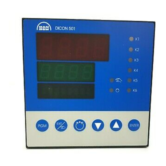
1 Introduction 1.1 Description This series of universal, freely configurable profile controllers/profile genera- tors is available in the formats 96mm x 96mm and 96mm x 48mm (portrait and landscape format). The instruments feature two 4-digit 7-segment dis- plays, five or eight LEDs for indicating the switching status and the operating modes, an 8-digit matrix display, as well as six keys for operation and configu- ration. -
Page 8: Typographical Conventions
1 Introduction 1.3 Typographical conventions 1.3.1 Warning signs The signs for Danger and Warning are used in this manual under the following conditions: Danger This sign is used when there may be danger to personnel if the instructions are disregard- ed or not followed accurately. -
Page 9: Identifying The Instrument Version
2 Identifying the instrument version 2.1 Type designation 703580/ 0 – – – – Format 96 mm x 96 mm 703585/ – 0 0 – 0 0 0 – – Format 48 mm x 96 mm and 96 mm x 48 mm (1) Basic type extension (5) Interface Format:... -
Page 10: Accessories
2 Identifying the instrument version 2.2 Accessories External relay module ER8 (3A/230V) Supply 110 — 240V AC Part no. 00405292 (no GL approval) External relay module ER8 (3A/230V) Supply 20 — 53V DC/AC Part no. 00405297 (no GL approval) External logic module EL8 (0/12V) Supply 110 —... -
Page 11: Installation
3 Installation 3.1 Location and climatic conditions The conditions at the instrument location must conform to the require- ments listed under Technical data. The ambient temperature at the loca- tion should be between –5 and 55 °C, at a relative humidity of not more than 95%. -
Page 12: Type 703585/1
3 Installation 3.2.2 Type 703585/1... Setup plug panel cut-out to IEC 61554 3.2.3 Type 703585/2... Setup plug panel cut-out to IEC 61554... -
Page 13: Edge-To-Edge Mounting
3 Installation 3.3 Edge-to-edge mounting Minimum spacing of the panel cut-outs Type horizontal vertical without setup plug: 703580/0... 11mm 30mm 703585/1... (portrait format) 11mm 30mm 703585/2... (landscape format) 30mm 11mm with setup plug: 703580/0... 11mm 65mm 703585/1... (portrait format) 11mm 65mm 703585/2... -
Page 14: Removing The Controller Chassis
3 Installation 3.6 Removing the controller chassis The controller chassis can be removed from the housing for servicing. h Press together the ribbed surfaces top and bottom (or left and right with the landscape format) and pull out the controller chassis. When inserting the controller chassis, care must be taken that the lugs (underneath the ribbed surfaces) snap into position. -
Page 15: Electrical Connection
4 Electrical connection 4.1 Installation notes The choice of cable, the installation and the electrical connection of the in- strument must meet the requirements of VDE 0100 “Regulations on the in- stallation of power circuits with nominal voltages below 1000 V” or the ap- propriate local regulations. -
Page 16: Connection Diagrams
4 Electrical connection 4.2 Connection diagrams 4.2.1 Type 703580 The electrical connection must only be made by suitably qualified personnel The instrument version can be identified by the type code. PROFIBUS-DP: v Interface Description B 703560.2.3 Thermocouples – – Resistance ϑ... - Page 17 4 Electrical connection Type 703580 Interface Output 5 Output 6 (Slot 5) (Slot 6) PROFIBUS DP -20/0/4—20mA -20/0/4—20mA +5 V – A GND 20 mA -10/0/2—10V -10/0/2—10V – RS485/ER8 RxD/ RxD/ 230V/1A 230V/1A ( ) – 5V(22V)/30mA* 5V(22V)/30mA* – RS422 ( ) –...
- Page 18 4 Electrical connection Type 703580 Output 1 (Slot 1) -20/0/4—20mA -10/0/2—10V 230V/1A 5V(22V)/30mA* * Supply for 2-wire transmitter (22V) The output must be config- ured accordingly 230V/3A v Section 10.4 “Outputs” 110—240V AC/DC 20—30V Contact protection circuit for the relay outputs: Logic inputs 3+4 Mains supply 56Ω/15nF between common-make/common-break...
-
Page 19: Type 703585 (Portrait And Landscape Format)
4 Electrical connection 4.2.2 Type 703585 (portrait and landscape format) The electrical connection must only be made by suitably qualified personnel. The instrument version can be identified by the type code. Earth the screen for the interface cable at one end only to TE. - Page 20 4 Electrical connection Type 703585 * Supply for 2-wire transmitter The output must be configured accordingly. v Section 10.4 “Outputs” Contact protection circuit for the relay outputs: 56Ω/15nF between common-make/common-break Thermocouples – – Resistance ϑ ϑ thermometer ϑ ϑ (3-wire) Resistance ϑ...
-
Page 21: Isolation
4 Electrical connection 4.3 Isolation For Type 703580 and Type 703585 (Type 703580 only) (Type 703580 only) - Page 22 4 Electrical connection...
-
Page 23: Operation
5 Operation 5.1 Displays and keys (1) configurable (4) Setup interface 7-segment display (display 1) Position depending on model; see dimensional drawings Type Height v Section 3.2 “Dimensions” 703580 13mm 703585 10mm factory setting: process value (2) configurable (5) Status indicators 7-segment display (display 2) 6 (3) yellow LEDs for the status indication of the outputs... -
Page 24: Operating Modes And States
5 Operation 5.2 Operating modes and states Operating mode/ Display Notes state Basic status The displays represent the values according to the display configuration. v Section 10.7 “Display” factory setting:- process value - setpoint of basic status BASIC ST - text The active parameter set is indicated by an additional decimal point. -
Page 25: Principle Of Operation
5 Operation 5.3 Principle of operation Basic status Initial status. Profile program Profile programs are selected here, start and the instant of start as well as the start conditions are defined. Profile program Profile programs are created here. editor Operating level This level is available for programming setpoints, displaying process varia- bles, altering system states and set-... -
Page 26: Entering Values And Selecting Settings
5 Operation Levels and Each level is divided into menus, thus creating a tree structure which has a se- menus lection or a value input at the end of each branch. = factory setting (return to basic status) 5.4 Entering values and selecting settings Value input h Increase parameter value with h Decrease parameter value with... -
Page 27: Operating Modes
5 Operation Code and time Time inputs and codes are entered digit by digit. input h Increase or decrease value (digit) with h Confirm entry and select next digit with All digits must be confirmed with The value is accepted automatically when the last digit is entered. -
Page 28: Manual Operating Mode
5 Operation 5.5.2 Manual operating mode For start-up and testing, a setpoint, the states of the operating contacts and the active parameter set can be input manually. Operating level The settings can be made at the operating level, under the menu item “System states”. -
Page 29: Automatic Operating Mode (Program Run)
5 Operation 5.5.3 Automatic operating mode (program run) Starting the The profile program is started with the program no. that was selected under profile program Program start Program number. h Start program with h Cancel current program with A program can also be selected, started and cancelled via the logic functions. The logic function “Program selection”... -
Page 30: Shifting The Setpoint
5 Operation 5.6 Shifting the setpoint Shifting the Using the “external setpoint with correction” function, the profile can be shift- profile ed upwards or downwards by the amount of the analogue input. The external setpoint is provided via one analogue input or through mathemat- ics. -
Page 31: Setpoint Switching
5 Operation 5.8 Setpoint switching If setpoint switching has been programmed, the active setpoint is modified from the keys. Setpoint inputs via the interface have priority. Predefined When predefining an external setpoint, setpoint switching takes place as external shown in the diagram below: setpoint Relevant Operating level r Setpoints... -
Page 32: Display Switching
5 Operation 5.9 Display switching Two display configurations can be defined which determine the display of val- ues and process variables on the 7-segment displays and the dot-matrix dis- play. The presentation in the dot-matrix display is only active in automatic mode. h Switch display with or automatic changeover after an adjustable time period. -
Page 33: Profile Program Start
6 Profile program start 6.1 Instant start of program The program is started with the program no. that was selected under Program start Program number. h Start program with h Cancel current program with A program can also be selected, started and cancelled via the logic functions. The logic function “program selection”... - Page 34 6 Profile program start...
-
Page 35: Profile Program Editor
7 Profile program editor 7.1 General 10 profile programs with up to 100 segments can be programmed; a total of 100 segments can be implemented. Profile programs are defined by programming setpoints and segment times or gradients segment by segment. The type of instrument programming (setpoint/segment time or setpoint/gradi- ent) can be configured and applies to the entire programming procedure. - Page 36 7 Profile program editor Creating When creating profile programs, the segments have to be edited one after an- profile other. programs h Change to the program editor with 2x and confirm with h Enter the code and confirm with h Enter the program number and confirm with Create program by entering the segment setpoint, segment time, etc.
-
Page 37: Editing Segments
7 Profile program editor PGM NO. (1—10) PGM EDIT Parameter Value/selection Description Insert segment SEG INS. 1—100 Segment number SEG NO. Value within the setpoint limits Segment setpoint SETPOINT 00:00:00—99:59:59 Segment time SEG TIME 00:00:00 0—999 Gradient DEGC/MIN Operating contact 1 OPCNTCT1 …... -
Page 38: Inserting Segments
7 Profile program editor 7.3 Inserting segments Segments can be inserted at any point in the profile. The subsequent segments will be automatically rearranged and re- numbered. The parameters of the seg- ment that was inserted (A02 in the ex- ample) are preconfigured to standard default values. -
Page 39: Deleting Segments
7 Profile program editor 7.5 Deleting segments When a segment is deleted, the subse- quent segments move up and are auto- matically renumbered. The profile will change according to the preconfigured setpoints. h Select “Delete segment” h Continue with h Enter the segment number of the segment to be deleted (in this case: 2) h Confirm with... -
Page 40: Temporary Alterations
7 Profile program editor 7.7 Temporary alterations Temporary alterations are alterations to Example: the current profile program in the pro- Segment Segment Segment gram editor. They are not stored in the setpoint time profile program store, which means that the alterations will be lost after a restart. -
Page 41: Operating Level
8 Operating level General At the operating level, it is possible to display and modify additional setpoints, indicate different process variables and program parameters and set the cur- rent system state. Access level h pressing 3x in the basic status or the manual operating mode. by ... - Page 42 8 Operating level Setting the time When the instrument is first switched on, the matrix display will ask you to set the real-time clock. h Confirm the message with The real-time clock is set at the operating level, under the menu Real-time clock Time.
-
Page 43: Parameter Level
9 Parameter level General Two parameter sets can be stored. Access level h pressing 4 times in basic status or the manual operating mode. by ... Access code The level is protected by a code. factory-set code: 0001 Selecting the Select the parameter set with parameter set PARAMETR... - Page 44 9 Parameter level PARAMETR PARASET1 Output limiting 0 — 100% 100% Maximum output limit -100 to +100% -100% Minimum output limit Minimum relay 0 — 60sec 0 sec Limitation of the switching rate on ON time switching outputs. 0 — 60sec 0 sec The parameter displays on the unit depend on the controller type that was selected.
-
Page 45: Configuration Level 1
10 Configuration level 1 General The following applies to the representation of parameters and functions on the unit: The parameter is not displayed when - the instrument features do not permit the function assigned to the parameter. Example: Output 3 cannot be configured if output 3 is not available to the instrument. - Page 46 10 Configuration level 1 r Inputs r analogue input 1—4 r transducer linearisation v Page 52 measurement correction constant cold junction temperature external cold-junction temperature display start display end range start range end filter time constant customized recalibration r start value end value supply frequency unit...
-
Page 47: Configuration Level 1 10.1 Controller
10 Configuration level 1 10.1 Controller The following are set here: controller type and input variables of the controller, setpoint limits, conditions for manual mode, presettings for self-optimisation and the fuzzy logic. CONFIG 1 CONTRL. Parameter Value/selection Description Controller type single-setpoint controller CTR.TYPE 1-SETPT... - Page 48 10 Configuration level 1 CONFIG 1 CONTRL. Parameter Value/selection Description Setpoint limits WLIMITS setpoint start -1999—0 to +9999 STARTVAL setpoint end -1999—400 to +9999 ENDVALUE 400. The setpoint limits are ineffective with setpoint input via the interface. For external setpoint with cor- rection, the correction value is limited.
-
Page 49: Limit Comparators
10 Configuration level 1 10.2 Limit comparators Limit comparators (limit monitors, limit contacts) are used to monitor an input variable (limit comparator process value) against a fixed limit value or another variable (limit comparator setpoint). When a limit is exceeded, a signal can be output or a function inside the controller initiated. - Page 50 10 Configuration level 1 CONFIG 1 LIMITC LIMITC1 Parameter Value/selection Description Switching 0—1—9999 digit DIFFERTL differential X Limit value AL -1999—0 to +9999 digit LIMIT Function on relay de-energised RANGEFCT RELDE-EN over/underrange relay energised RELENERG If a limit comparator is connected to an output, then the setting “Output signal on over/underrange”...
- Page 51 10 Configuration level 1 Absolute At the time of alteration, the limit comparator acts in accordance with its func- tion. Relative The limit comparator is in the OFF status. An alteration of the limit value or the (limit comparator) setpoint could cause the limit comparator to switch ON.
-
Page 52: Inputs
10 Configuration level 1 10.3 Inputs The analogue inputs are configured here. CONFIG 1 INPUTS Parameter Value/selection Description Analogue input 1 Configuration of the analogue inputs ANALOG 1 as in example “Analogue input 1” below. Analogue input 4 ANALOG 4 Supply frequency 50Hz PWRFREQ... - Page 53 10 Configuration level 1 CONFIG 1 INPUTS ANALOG 1 Parameter Value/selection Description Linearisation linear LINTAB LINEAR Pt 100 PT100 Pt 1000 PT1000 Pt 500 PT500 Pt 50 PT50 Cu 50 CU50 KTY21-6 (1kΩ at 25°C)* Pt K9 PTK9 Ni 100 NI100 Fe-Con J TC TPE J...
- Page 54 10 Configuration level 1 CONFIG 1 INPUTS ANALOG 1 Parameter Value/selection Description Constant 0 — 50 — 100 digit CJTEMP cold-junction temperature for temperature of cold-junction thermocouples thermostat External analogue input 1 EXTTEMP ANALOG 1 cold-junction temperature for analogue input 4 ANALOG 4 thermocouples measurement of the cold-junction...
- Page 55 10 Configuration level 1 CONFIG 1 INPUTS ANALOG 1 Parameter Value/selection Description Customized RECAL recalibration Start value STARTVAL -1999 — 0 to +9999 digit End value ENDVALUE -1999 — 1 to +9999 digit (for explanation, see below) factory-set access code: 0004 Different from all the other settings, the input of the start and end values is linked to the present...
- Page 56 10 Configuration level 1 Procedure Apply two measurement points ((1), (3)), one after another, to the controller; they should be as far apart as possible. At these measurement points, enter the required display value (start value, end value) in the controller. A reference instrument is most convenient for deter- mining the measured values M1 and M2.
-
Page 57: Outputs
10 Configuration level 1 10.4 Outputs The outputs are configured here. CONFIG 1 OUTPUTS Parameter Value/selection Description Output 1 Configuration of the outputs as in OUTPUT1 the example “Output 1” below. Output 6 OUTPUT6 Factory setting are shown bold. CONFIG 1 OUTPUTS OUTPUT1 Parameter... - Page 58 10 Configuration level 1 CONFIG 1 OUTPUTS OUTPUT1 Parameter Value/selection Description Output signal for 0 — 10V SIGNAL 0 - 10 V analogue output 2 — 10V 2 - 10 V -10 to +10V -10- 10V 0 — 20mA 0 - 20mV 4 —...
-
Page 59: Profile Controller
10 Configuration level 1 10.5 Profile controller The profile controller/generator is configured here. In addition, the response to a power failure, the profile run and the type of programming are defined here. CONFIG 1 PROF CTR Parameter Value/selection Description Function profile controller PROGRFCT PROFCTRL... - Page 60 10 Configuration level 1 CONFIG 1 PROF CTR Parameter Value/selection Description Response on continue RANGEFCT CONTINUE overrange/ program stop PGM STOP underrange Program stop: The program will be continued after the end of the measurement overrange/underrange. Function generator control FCT CTRL GENCTRL control operating contact 1...
- Page 61 10 Configuration level 1 Continue at In the event of a power failure, the sign of the gradient (falling or rising) at the process value time of the power failure is stored. After the supply voltage has been restored, the program is checked from the beginning to find matching process values and setpoints.
-
Page 62: Maths And Logic Module
10 Configuration level 1 10.6 Maths and logic module This menu is displayed only with enabled maths and logic module. CONFIG 1 MATHSLOG Parameter Value/selection Description Mathematics 1 Configuration of mathematics as MATHS 1 shown in example “Maths 1” below. Mathematics 2 MATHS 2 Logic 1... - Page 63 10 Configuration level 1 CONFIG 1 MATHSLOG MATHS 1 Parameter Value/selection Description Linearisation linear LINTAB LINEAR Pt 100 PT100 Pt 1000 PT1000 Pt 500 PT500 Pt 50 PT50 Cu 50 CU50 KTY21-6 Pt K9 PTK9 Ni 100 NI100 Fe-Con J TC TPE J NiCr-Con E TC TPE E...
- Page 64 10 Configuration level 1 Formula input - The formula character string consists of ASCII-characters and has a ma- ximum length of 70 characters. - The formula can only be entered via the setup program. - The formulae can be entered freely according to the usual mathematical rules.
- Page 65 10 Configuration level 1 Note Variable name storage address (binary) ADRB output limit comparator 1 … … output limit comparator 8 SK1 — SK8 operating contact 1 — operating contact 8 logic input 1 … … logic input 8 logic 1 logic 2 PEND program end...
- Page 66 10 Configuration level 1 Syntax Function absolute value of a ABS(a) Examples: ABS(-12) (returns the value 12) ABS(13.5+E3) EXP(a) exponential function e Examples: EXP(1) (returns the value 2.718) EXP(E1/100) integer portion of a INT(a) Examples: INT(8.3) (returns the value 8) INT(E1) decimal portion of a FRC(a)
-
Page 67: Display
10 Configuration level 1 Note Variable name program end PEND tolerance band signal Constants Note Constant name TRUE logic 1 logic 0 FALSE Enabling the The maths and logic module can be enabled through a code via the setup pro- maths and gram. - Page 68 10 Configuration level 1 Arrangement of the displays CONFIG 1 DISPLAY DSPCONF1 Parameter Value/selection Description Display 1 DISPLAY1 Display value no function DISPLVAL NO FUNCT analogue input 1 ANALOG 1 analogue input 4 ANALOG 4 mathematics 1 MATHS 1 mathematics 2 MATHS 2 process value setpoint (present)
- Page 69 10 Configuration level 1 CONFIG 1 DISPLAY DSPCONF1 Parameter Value/selection Description Display 3 DISPLAY3 Display value no function DISPLVAL NO FUNCT analogue input 1 ANALOG 1 analogue input 4 ANALOG 4 mathematics 1 MATHS 1 mathematics 2 MATHS 2 process value setpoint (present) SETPOINT ramp end value...
-
Page 70: Logic Functions
10 Configuration level 1 10.8 Logic functions Functions are assigned here to the logic signals of the logic inputs, limit com- parators, operating contacts, tolerance band signal, profile program end signal and of the logic module. CONFIG 1 LOGICFCT Parameter Value/selection Description Logic input 1 no function... - Page 71 10 Configuration level 1 Switching The logic functions are activated through logic inputs (floating contacts action (switches/relay contacts)), limit comparators, operating contacts or logic. The functions are divided into two groups: Edge-triggered The logic functions react to switch-on edges. functions The following functions are edged-triggered: - start/stop self-optimisation - start profile program...
- Page 72 10 Configuration level 1 Example: The process value is to be selected via one logic input and the state of one op- erating contact. This results in the following assignment: Z1 - logic input 1 Z2 - operating contact 1 Setpoint switching Process value Profile program...
-
Page 73: Interface
10 Configuration level 1 10.9 Interface CONFIG 1 INTERFCE Parameter Value/selection Description Protocol type MODbus/Jbus PROTOCOL MODBUS MODbus int MODINT Data format DATAFMT Baud rate 1200 bps BAUDRATE 1200 2400 bps 2400 4800 bps 4800 9600 bps 9600 19200 bps 19200 Parity no parity... - Page 74 10 Configuration level 1...
-
Page 75: Optimisation
11 Optimisation 11.1 Self-optimisation Procedure Self-optimisation (SO) establishes the optimum controller parameters for PID or PI controllers. Depending on the controller type, the following controller parameters can be defined: Reset time (Tn1, Tn2), derivative time (Tv1, Tv2), proportional band (Xp1, Xp2), switching cycle time (Cy1, Cy2), filter time constant (dF) The controller selects one of two procedures (a or b), depending on the size of the control deviation:... -
Page 76: Checking The Optimisation
11 Optimisation 11.2 Checking the optimisation Start-up The optimum adjustment of the controller to the process can be checked by procedure recording the start-up with the control loop closed. The diagrams below indi- cate possible maladjustments and how these can be corrected. Control The control response of a third-order control loop of a PID controller is shown response... -
Page 77: Fuzzy Parameters
11 Optimisation 11.3 Fuzzy parameters In addition to the algorithms for the various controller structures, the con- troller software also includes a fuzzy module. This can be used to improve both the control and the disturbance response of controllers with I-action. When the fuzzy module is activated, the output y is made up of the control- ler output and the output signal of the... - Page 78 11 Optimisation Action Reaction ↑ disturbance amplitude reduced, stabilisation time increased disturbance amplitude increased, stabilisation time reduced ↑ stabilisation time reduced stabilisation time increased If the fuzzy module is not activated (Fc1=0), Fc2 is also ineffective. The action and sensitivity of the fuzzy parameters depend largely on the process to be controlled.
-
Page 79: Retrofitting Of Cards
12 Retrofitting of cards The following steps are necessary for retrofitting cards: Only qualified personnel are permitted to retrofit cards. The cards can be damaged by electrostatic discharges. Avoid elect- rostatic charges during fitting and removal. Carry out the card change on a workbench which is earthed. - Page 80 12 Retrofitting of cards Configuring the The retrofitable analogue inputs 3 and 4 are supplied ex-factory as universal analogue input. They can be reconfigured as voltage input for certain measuring ranges input (-10/0/2—10V and -1V—1V). h Re-arrange push-on jumpers as in the diagram Universal input (remaining ranges) Voltage 10/0/2 —...
- Page 81 12 Retrofitting of cards Removing the h Pull off setup plug controller h Press together the ribbed surfaces chassis on the panel top and bottom (or left and right with landscape format) and pull out the controller chassis. Assigning the h Determine the corresponding slot for the card slot Type 703580 only...
- Page 82 12 Retrofitting of cards Inserting the h Pull off the guide plate (1) card h Insert card into the guide until the projections on the card snap into the notches provided (2) Inserting the h Fit on the guide plate controller h Push the controller chassis into the case until the lugs (underneath the chassis...
-
Page 83: Interfaces
13 Interfaces 13.1 RS422/485 interfaces The controller can be integrated into a data network via the interface. Func- tions which can be implemented include: - process visualisation - system control - recording/logging The bus system is based on the master-slave principle. A master computer can address up to 31 controllers and instruments (slaves). -
Page 84: Profibus-Dp
13 Interfaces 13.2 PROFIBUS-DP Fieldbus The controller can be incorporated into a fieldbus system according to the PROFIBUS-DP standard, via the PROFIBUS-DP interface. This PROFIBUS variant has been especially designed for the communication between automa- tion systems and distributed peripheral devices at the field level, and is opti- mised for speed. -
Page 85: Accessories
14 Accessories 14.1 External relay module/logic module ER8/EL8 By using the external relay module ER8 or logic module EL8, the controller can be expanded by eight relay outputs (changeover contacts) or logic outputs (0/ 12 V). Communication with the controller occurs via the RS422/485 interface. All controller signals for switching outputs can be output by the module. -
Page 86: Setup Program With Commissioning Software
14 Accessories 14.2 Setup program with commissioning software Setup program ® A setup program for NT4.0/2000/XP/Vista/7 (32/64 bit) is available Windows for easy configuration of the profile controller. Hardware requirements: - 512 Mbyte RAM - CD-ROM drive - 50 Mbyte available on hard disk - 1 free serial interface or USB interface The program shows the current configuration as a list in the background. -
Page 87: Technical Data
15 Appendix 15.1 Technical data Thermocouple input Designation Range Meas. accuracy Ambient temperature error ≤ Fe-Con L -200 — +900°C 0.25% 100 ppm per °C ≤ Fe-Con J EN 60 584 -200 — +1200°C 0.25% 100 ppm per °C ≤ Cu-Con U -200 —... - Page 88 15 Appendix Outputs Relay changeover contact contact rating 3A at 250VAC resistive load contact life 150 000 operations at rated load Ω contact protection circuit /15nF between common-n.o. make/common-n.c. break Logic 0/5V 0/22V current limiting 20mA 30mA Solid-state relay contact rating 1A at 230V Voltage output signals...
- Page 89 Registernummer TR1117 DIN EN 14 597 DICON 501 GL - Hardware Germanischer Lloyd Certificate GL-Baumusterprüfung DICON 501 GL - Software No. 15 694-00 HH Kategorie C, EMC1 c UL us Underwriters Laboratories E 201387 UL 61010-1 DICON 401/501 CAN/CSA-C22.2 No.61010-1...
-
Page 90: Alarm Messages And Display Priorities
15 Appendix 15.2 Alarm messages and display priorities Priority Display Possible error/ Assignment Error handling notes check/repair/replacement Matrix 7-segment high watchdog or power-on controller replace controller when ÈÈÈÈÈÈÈÈ 8888. will trigger initialisation (reset) initialisation is longer than 5sec +LEDs (blinks) 8888. - Page 91 15 Appendix Priority Display Possible error/ Assignment Error handling notes check/repair/replacement Matrix 7-segment high (Text) ( )* text (logic input 1) … … text display (logic input 8) (Text) (Text) ( )* text display (limit comparator 1) … … text display (limit comparator 8) (Text) (Text) ( )*...
- Page 92 15 Appendix Table: Assignment of the measurement inputs/response of the outputs in the event of an error (to be filled in by the user)
-
Page 93: Character Set For Matrix Display
15 Appendix 15.3 Character set for matrix display The special characters for text entry in the setup program are shown here. They are entered from the keys using the key combination Alt + XXX. 200 — 210 reserved for bar graph display... -
Page 94: Instrument Features (Configuration Level 2)
15 Appendix 15.4 Instrument features (configuration level 2) The software version and the hardware features of the profile controller are shown here. CONF 2 Parameters Value/selection Description Version version number VERSION 50.0X.0X VDN number standard version VDN NO. STANDARD VDN number XXX.XXXX (modification of standard version) -
Page 95: Notes For Instruments With Germanischer Lloyd (Gl) Approval
15 Appendix 15.5 Notes for instruments with Germanischer Lloyd (GL) approval The information below is intended to supplement or replace the details that have already been given. 15.5.1 Technical data Ambient conditions according to application category C for enclosed areas Temperature -5 to 55°C ≤... - Page 96 15 Appendix The instrument can only be used with restrictions on the bridge, since a continuous dimming of the display brightness is not possi- ble! it is recommended that a print-out of the setup program be kept on site, together with the technical documentation for the controller (can be requested, if necessary).
-
Page 97: Index
16 Index End value 58 External relay module 85 Accessories 10 External setpoint with correction 30 Action 49 Alarm messages 90 Alteration, temporary 40 Filter time constant 54 Altering Fitting into position 13 segment time of current segment 40 Formula input 64 setpoint in current segment 40 Front panel, cleaning of 13 setpoint in subsequent segment 40... - Page 98 16 Index editing 37 free 41 Operating contact 28 – inserting 37 Operating level 25 Segment change 29 Operating mode 24 Segment setpoint automatic 24 altering in current program 29 manual 24 Segment time, residual 33 Operation 23 Selection 27 Optimisation 76 Self-optimisation 24 Output 9...
- Page 99 Profile program No.:___ Segment No. is automatically increased by 1! P P P P P P P P X ___:___:___ ___:___:___ ___:___:___ ___:___:___ ___:___:___ ___:___:___ ___:___:___ ___:___:___ ___:___:___ ___:___:___...
- Page 100 JUMO GmbH & Co. KG JUMO Instrument Co. Ltd. JUMO Process Control, Inc. Street address: JUMO House 6733 Myers Road Moritz-Juchheim-Straße 1 Temple Bank, Riverway East Syracuse, NY 13057, USA 36039 Fulda, Germany Harlow, Essex CM20 2DY, UK Phone: 315-437-5866...
Need help?
Do you have a question about the DICON 401 and is the answer not in the manual?
Questions and answers
Comment appliquer la consigne svp type dicon 501
To apply the settings for a JUMO 401 with DICON 501 type, use the following methods:
1. Service Mode: Access the device's Service mode to configure and test settings directly on the unit.
2. Setup Program: Use the Calibrate and Test function in the setup program on a connected computer to apply and verify settings.
Settings typically include input configuration (e.g., 0–20 mA or 0–10 V), output testing, and operational parameters. If retrofitting inputs, only the 500/501 types support this, and only in slots A and B. Ensure hardware compatibility for voltage ranges like -10/0/2–10 V.
This answer is automatically generated