
Related Manuals for JUMO AQUIS 500 pH


Summary of Contents for JUMO AQUIS 500 pH
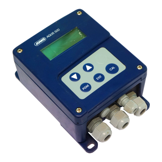
- Page 1 JUMO AQUIS 500 pH Transmitter/Controller for pH, ORP and - (ammonia) concentration Type 202560 B 20.2560.0 Operating Instructions 2012-04-12/00475451...
- Page 2 WARNING: A sudden malfunction of the instrument, or one of the sensors connected to it, could potentially result in dangerous, imprecise dosing! Suitable preventive measures must be in place to prevent this from happening. Note: Please read these Operating Instructions before placing the instrument in operation.
-
Page 3: Table Of Contents
Contents Typographical conventions ............6 Warning signs ....................6 Note signs ....................6 Description ................7 Identifying the instrument version ........... 8 Nameplate ....................8 Type designation ..................9 Scope of delivery ..................9 Accessories (in delivery package) ..............10 Accessories (optional) ................11 Electrical connection .............. 12 Installation notes ..................12 Electrical isolation ..................13 General .......................14... - Page 4 Contents Commissioning ............... 46 Fast start ....................46 Setup examples ..................47 Calibration ................68 pH electrode ....................68 pH antimony electrode ................76 ORP electrode ....................76 Ammonia (NH )- cell ..................80 Setup program ................ 82 Function .....................82 Eliminating faults and malfunctions ........83 10.1 Possible faults ....................83 Appendix ..................
- Page 5 Ziffern Measurement mode MIN/MAX values 1-point calibration Mounting location 1-point calibration, ammonia 1-point calibration, pH 2-point calibration Nameplate 2-point calibration, pH Normal display 3-point calibration 3-point calibration, pH Operator level Output level display – Accessories Outputs Acidity errors Overview of MANUAL mode Administrator level Administrator rights Alkaline errors...
-
Page 6: Typographical Conventions
1 Typographical conventions Warning signs Danger This symbol is used when there may be danger to personnel if the instructions are disregarded or not followed accurately! Caution This symbol is used when there may be damage to equipment or data if the instructions are ignored or not followed accurately! Caution This symbol is used where special care is required when handling components... -
Page 7: Description
2 Description General The instrument is used for measuring/controlling the pH, ORP or NH (ammonia) concentration. The function is switchable on the instrument itself. Depending on the measured variable, combination electrodes (e. g. pH/ORP combination electrodes, gas-sensitive sensors) or split versions (glass/metal electrodes with a separate reference electrode) can be readily connected. -
Page 8: Identifying The Instrument Version
3 Identifying the instrument version Nameplate on the VARTN: 20/00491200 transmitter JUMO AQUIS 500 pH Fulda, Germany Typ: 202560/10-888-000-000-000-23/000 www.jumo.net F-Nr.: 0168122901012150001 AC 110..240V -15/+10% 48..63Hz < 14VA The date of manufacture is coded in the “F-Nr.” (serial number): 0935 means manufactured in year 2012 / week 15... -
Page 9: Type Designation
3 Identifying the instrument version Type designation (1) Basic type 202560 JUMO AQUIS 500 pH Transmitter/controller for pH, ORP, - (ammonia) concentration and temperature (2) Basic type extensions for panel mounting in surface-mountable housing (3) Output 1 (for principle measurement variable or continuous controller) no output analog output 0(4) —... -
Page 10: Accessories (In Delivery Package)
3 Identifying the instrument version Accessories (in delivery package) Contents Designation 3 x plug-in screw terminals 1 x large plug-in link 1 x small plug-in link 1 x cable clip for cable diameter > 5 mm 2 x cable clips for cable diameter < 5 mm 1 x cable clip for cable diameter <... -
Page 11: Accessories (Optional)
PC interface, including USB/TTL converter and 00456352 adapter (USB connecting cable) Fixing for suspended fitting 00453191 The pole-mounting kit is needed for mounting the protection canopy. Using the pole-mounting kit, the JUMO AQUIS 500 can be fitted to a pole (e.g. support pillar or railing). -
Page 12: Electrical Connection
4 Electrical connection Installation notes The electrical connection must only be carried out by qualified professional persons ! The choice of cable, the installation and the electrical connection must conform to the requirements of VDE 0100 “Regulations on the Installation of Power Circuits with Nominal Voltages below 1000 V”... -
Page 13: Electrical Isolation
4 Electrical connection Electrical isolation Setup interface 3700 V AC Relay contacts Binary input 30 V AC 50 V DC Analog output 1 Main input 30 V AC 50 V DC Analog output 2 Secondary input (Pt100 / Pt1000) 30 V AC 50 V DC Supply for 2-wire transmitter... -
Page 14: General
4 Electrical connection General Opening the instrument Remove four screws (1) and swing down the top section. Connection 4.4.1 pH combination electrode / ORP combination electrode Fabricating the connecting cable Strip the cable as shown in the diagram. Insulate the exposed shielding with a shrink-sleeve (1), to prevent short- circuits. - Page 15 4 Electrical connection Connecting the The electrical connection for the surface-mountable housing is easily cables accessible when the instrument is folded out. The connection cable between sensor and transmitter must be a shielded cable with a diameter of 8 mm max. The instrument contains a guide plate that ensures an optimum cable path.
- Page 16 4 Electrical connection Asymmetrical connection of a combination electrode (standard) Lead the connecting cables in through the cable glands. Lay the signal cable as shown in the diagram. Use the cable clip (3) to clamp the signal cable to the shielding. Connect the cores as assigned below, and see Chapter 4.5 “Terminal assignments”, page 19.
- Page 17 4 Electrical connection Asymmetrical connection of a combination electrode with integrated temperature sensor (SMEK) Lead the connecting cables in through the cable glands. Lay the signal cable as shown in the diagram. Use the cable clip (3) to clamp the signal cable to the shielding. Connect the cores as assigned below, and see Chapter 4.5 “Terminal assignments”, page 19.
- Page 18 4 Electrical connection Symmetrical connection of a combination electrode with separate temperature sensor Lead the connecting cables in through the cable glands. Lay the signal cables as shown in the diagram. Use the cable clips (3) to clamp each signal cable to the shielding. Connect the cores as assigned below, and see Chapter 4.5 “Terminal assignments”, page 19.
-
Page 19: Terminal Assignments
4 Electrical connection Terminal assignments Connection Screw terminals Supply voltage Supply voltage (23): 1 N (L-) 110 — 240 V AC -15/+10%, 48 — 63 Hz 2 L1 (L+) Supply voltage (25): 20 — 30 V AC/DC, 48 — 63 Hz Supply voltage (30): 12 —... -
Page 20: Outputs
4 Electrical connection Connection Screw terminals Outputs Analog output 1 + 13 - 14 0 — 20 mA resp. 20 — 0 mA or 4 — 20 mA resp. 20 — 4 mA 0 — 10 V resp. 10 — 0 V (electrically isolated) Analog output 2 + 15... -
Page 21: Isfet-Ph Combination Electrode According To Data Sheet 20.1050
4 Electrical connection ISFET-pH combination electrode according to data sheet 20.1050 Connection Color Screw terminals Cap- JUMO AQUIS 500 pH adapter Supply voltage for ISFET sensor Supply voltage blue 11 L+ DC ± 5 V, 5 mA black green 13 L-... -
Page 22: Mounting
5 Mounting General Mounting Find a location that ensures easy accessibility for the later calibration. location The fastening must be secure and must ensure low vibration for the instrument. Avoid direct sunlight! Permissible ambient temperature at the installation location: -10 to 55°C with max. -
Page 23: Pipe Installation Set / Weather Protection Roof
The pipe installation set is also suitable for horizontal pipes. DIN rail installation set The DIN rail installation set for JUMO AQUIS 500 (sales no.:20/00) can be used to attach the instrument to a 35 mm x 7.5 mm DIN rail as defined in DIN EN... -
Page 24: Mounting In A Panel
5 Mounting Mounting in a panel Drilling template See section 12.2 "Panel cut-out", page 101. The panel must be sufficiently thick to achieve the specified IP65 enclosure protection! Prepare the panel cut-out and holes based on the drill template. Place the control panel (1) in the panel cut-out and fasten it with screws (2) spacing rollers (3) and nuts (4). - Page 25 5 Mounting The mounting set (sales no.: 20/00530470) consists of parts (1), (2) and (3). Make the electrical connection. Screw on two stud bolts (1). Fasten the cover (2) with two knurled nuts (3). Depth behind ~ 55 panel...
-
Page 26: Operation
6 Operation Controls (1) Transmitter (3) Control panel (2) LC display... -
Page 27: Lc Display
6 Operation LC display 6.2.1 Measurement mode (normal display) (10) (11) Relay K1 is active Output mode - Hand (manual operation) Relay K2 is active - Hold (Hold operation) AL R1 = alarm, relay K1 Measurement AL R2 = alarm, relay K2 Unit ALR12 = alarm, relay K2+K2 Temperature of medium... -
Page 28: Principle Of Operation
6 Operation Principle of operation Meas. mode > 3 sec EXIT CTRL. SETPOINTS SETPOINT 1 < 2 sec or timeout SETPOINT (adjustable) MIN/MAX VALUES < 2 sec EXIT OUTPUT LEVEL Controller 1 Controller < 2 s EXIT MANUAL MODE OVERVIEW <... - Page 29 6 Operation 6.3.1 Operation in levels Measurement mode (normal display); see Chapter 6.4 “Measurement mode”, page 31 CTRL. SETPOINTS MIN/MAX values see Chapter 6.5.1 “MIN/ MAX values”, page 31 Output level display see Chapter 6.5.2 “Output level display”, page 32 Manual mode overview see Chapter 6.6 “MANUAL mode / simulation mode”,...
- Page 30 6 Operation Measurement mode ADMINISTRATOR LEVEL BASIC SETTINGS, see Chapter 6.9.4 “Basic settings”, page 42 SENSOR MONIT. REF. MONIT. GLASS EL. RE-INITIALIZE DEVICE CALIB. LEVEL, see Chapter 6.9.5 “Calibration level”, page 43 1-POINT CALIB. 2-POINT CALIB. 3-POINT CALIB. CALIB. ENABLE ENABLE 1-POINT CALIB.
-
Page 31: Measurement Mode
6 Operation Measurement mode 6.4.1 Normal display Presentation The compensated pH value and temperature of the medium are shown in normal display. MEASURE -> Measurement mode 25.0°C -> Temperature of the sample medium 7.34 pH-> pH of the medium (compensated for the reference/ comparison temperature –... -
Page 32: Output Level Display
6 Operation The values for the main measurement and temperature are not allocated to one another (e. g. the max. value of the main variable was 7.33 pH and 25.0°C the max. temperature value). In order to return to the measurement mode: Press the key or wait for the timeout. -
Page 33: Manual Mode / Simulation Mode
In MANUAL mode the settings for "higher order controllers" are taken into consideration. 6.6.1 MANUAL mode via "higher order control functions" Higher order The JUMO AQUIS 500 is configured for higher order control functions when switching the following setting is made: functions User level / controller channel 1 or 2 / control type Limit value or pulse length or pulse frequency or modulating or continuous controller. - Page 34 To exit HOLD mode, press the keys for longer than 3 seconds. EXIT Control is no longer through the JUMO AQUIS 500. The output level of the controller channels is 0%. Controller channel 1 is activated by the key. In this case the output level of controller channel 1 is 100%.
-
Page 35: Simulation Of Switching Outputs
Set Administrator level / Password / Parameter level / Switching output 1 or 2 / Manual mode no simulation, Inactive or Active. No simulation = No manual mode, control is via the JUMO AQUIS 500. Inactive = Relay K1 or K2 is de-energized. - Page 36 Administrator level / Password / Parameter level / Analog output 1 or 2 / Simulation / Off or On. With "On" the output takes on the value of the "Simulation value" parameter. When the JUMO AQUIS is in display mode, the word MANUAL appears in the status line of the display. Deactivation Administrator level / Password / Parameter level / Analog output 1 or 2 / Simulation / Off.
-
Page 37: Hold Mode
6 Operation HOLD mode In HOLD status the outputs take on the states programmed in the relevant parameter (controller channel, switching output or analog output). This function can be used to "freeze" switching outputs and the analog outputs of the instrument. This means the current status of the output will be retained even when the measured value changes. -
Page 38: Operator Level
6 Operation Operator level All the parameters that have been enabled by the administrator (Administrator level, see “Administrator level”, page 38) can be edited in this level. All other parameters (marked by a key ) can only be read. Press the key for longer than 3 seconds. - Page 39 6 Operation 6.9.1 Administrator levels ADMIN. LEVEL PASSWORD EXIT PARAMETER LEVEL timeout (adjustable) EXIT ENABLE LEVEL timeout EXIT BASIC SETTINGS timeout EXIT CALIBRATION LEVEL timeout EXIT CALIB. ENABLE timeout DELETE EXIT LOGBOOK timeout...
-
Page 40: Administrator Rights
6 Operation 6.9.2 Parameter level Here you can make the same settings as at the operator level. However, since the user has administrator rights in this case, parameters can also be altered that would be locked at the operator level. For the list of adjustable parameters, see Chapter 6.8 “Operator level”, page 38ff. - Page 41 6 Operation Pulse period Minimum ON time Output level limit Maximum pulse frequency Hysteresis Pull-in delay Drop-out delay Controller alarm In Hold mode In event of error Max. process value Min. process value CTRL.SPEC.FUNCT. (Special controller function) I switch-off Separate controllers Manual mode SWITCH OUTPUT 1 or SWITCH OUTPUT 2 Function...
-
Page 42: Basic Settings
6 Operation DISPLAY Language Lighting LCD inverse Meas. display type Lower display Upper display Bar graph calibration start Bar graph calibration end MIN/MAX reset Operator timeout Contrast 6.9.4 Basic settings The basic settings for the instrument are defined at this level. The parameters are altered by keys. -
Page 43: Point Calibration
6 Operation 6.9.5 Calibration level 1-POINT CALIB. (1-point calibration) Only the cell zero point is shifted in this case. Slope errors are not taken into account. This method can only be recommended with reservation. see Chapter 8 “Calibration”, page 68ff. 2-POINT CALIB. -
Page 44: Device Info
MONIT. GLASS EL. -> OFF 6.11 Controller function Simple In the JUMO AQUIS 500, simple switching functions, such as alarm contacts switching and limit comparators or the signal from the calibration timer, are configured at functions the parameter level, through the parameters for “Switching output 1 or 2”. - Page 45 6 Operation Operator level Switching output 1 / 2 Explanation parameters no switching function and none no control function required the instrument should have the higher-level Controller 1 control the instrument should have the higher-level Controller 2 control Controller alarm 1 / 2 Controller alarm main variable main variable...
-
Page 46: Commissioning
7 Commissioning Fast start This is a recommendation for configuring the instrument reliably in a short time. If you check the setting options from this list before starting the configuration, you can avoid timeouts during configuration. Mount the instrument, see Chapter 5 “Mounting”, page 22. Install the instrument, see Chapter 4 “Electrical connection”, page 12 ff. -
Page 47: Setup Examples
7 Commissioning Setup examples 7.2.1 Measurement of pH (standard sensor) Range: 0 — 14 pH Output signal: 0 — 20 mA Temperature measurement: manual Controller function: Sensor monitoring: Call up administrator Meas. mode level > 3 s EXIT CTRL. SETPOINTS <... - Page 48 7 Commissioning Call up basic settings ADMIN. LEVEL PASSWORD EXIT PARAMETER LEVEL timeout (adjustable) EXIT ENABLE LEVEL timeout EXIT BASIC SETTINGS timeout continue on next page EXIT CALIBRATION LEVEL timeout EXIT CALIB. ENABLE timeout EXIT DELETE LOGBOOK timeout...
- Page 49 7 Commissioning Basic settings Operating mode for the main pH standard input: pH antimony pH ISFET NH (ammonia) procedure Monitor maximum Unit for ORP Unit for NH impedance of reference - mV - ppm electrode? - customized - customized - Yes (0 —100 kOhm) Monitor impedance of glass electrode? - Min.
- Page 50 7 Commissioning Call up the parameter level ADMIN. LEVEL PASSWORD EXIT PARAMETER LEVEL continue on timeout next page (adjustable) EXIT ENABLE LEVEL timeout EXIT BASIC SETTINGS timeout EXIT CALIBRATION LEVEL timeout EXIT CALIB. ENABLE timeout DELETE EXIT LOGBOOK timeout...
- Page 51 7 Commissioning Concluding instrument settings Input for Sensor type: no sensor (manual) temperature Unit: °C Manual temperature: 25.0°C (present temperature of medium) Filter time constant: 00:00:02 Analog output 1 Signal selector: Main value Signal type: 0 — 20 mA Scaling start: 0.00 pH Scaling end: 14.00 pH...
- Page 52 7 Commissioning 7.2.2 Measurement of pH (standard sensor) Range: 2 — 12 pH Output signal: 4 — 20 mA Temperature measurement by Pt100 Controller function: pulse width controller Setpoint 1: pH 6.5 Setpoint 2: pH 8.5 Sensor monitoring: Call up administrator Meas.
- Page 53 7 Commissioning Call up basic settings ADMIN. LEVEL PASSWORD EXIT PARAMETER LEVEL timeout (adjustable) EXIT ENABLE LEVEL timeout EXIT BASIC SETTINGS timeout continue on next page CALIBRATION EXIT LEVEL timeout CALIB. EXIT ENABLE timeout EXIT DELETE LOGBOOK timeout...
- Page 54 7 Commissioning Basic settings Operating mode for the main pH standard input: pH antimony pH ISFET NH (ammonia) procedure Monitor maximum Unit for ORP Unit for NH impedance of reference - mV - ppm electrode? - customized - customized - Yes (0 —100 kOhm) Monitor impedance of glass electrode? - Min.
- Page 55 7 Commissioning Call up parameter level ADMIN. LEVEL PASSWORD EXIT PARAMETER LEVEL continue on timeout next page (adjustable) EXIT ENABLE LEVEL timeout EXIT BASIC SETTINGS timeout CALIBRATION EXIT LEVEL timeout CALIB. EXIT ENABLE timeout DELETE EXIT LOGBOOK timeout...
- Page 56 7 Commissioning Concluding instrument settings Input for Sensor type: Pt100/Pt1000 temperature Unit: °C Filter time constant: 00:00:02 Offset: 0.0°C Controller Controller type: pulse width output channel 1 Setpoint: 6.5 pH MIN / MAX contact: MIN contact Proportional band: as required Reset time: as required Derivative time:...
- Page 57 7 Commissioning MAX setpoint: as required MIN setpoint: as required Alarm delay: as required Switching Function: CONTROLLER 1 output 1 Switching Function: CONTROLLER 2 output 2 Analog output 1 Signal selector: Main value Signal type: 4 — 20 mA Scaling start: 2 pH Scaling end: 12 pH...
- Page 58 7 Commissioning 7.2.3 ORP measurement Range: 0 — 1000 mV Output signal: 0 — 10 V Controller function: limit controller Limit: 600 mV Call up administrator Meas. mode level > 3 s EXIT CTRL. SETPOINTS SETPOINT 1 < 2 sec or timeout SETPOINT (adjustable)
- Page 59 7 Commissioning Call up basic settings ADMIN. LEVEL PASSWORD EXIT PARAMETER LEVEL timeout (adjustable) EXIT ENABLE LEVEL timeout EXIT BASIC SETTINGS timeout continue on next page EXIT CALIBRATION LEVEL timeout EXIT CALIB. ENABLE timeout DELETE EXIT LOGBOOK timeout...
- Page 60 7 Commissioning Basic settings Operating mode for the main pH standard input: pH antimony pH ISFET NH (ammonia) procedure Monitor maximum Unit for ORP Unit for NH impedance of reference - mV - ppm electrode? - customized - customized - Yes (0 —100 kOhm) Monitor impedance of glass electrode? - Min.
- Page 61 7 Commissioning Call up parameter level ADMIN. LEVEL PASSWORD EXIT PARAMETER LEVEL continue on timeout next page (adjustable) EXIT ENABLE LEVEL timeout EXIT BASIC SETTINGS timeout CALIBRATION EXIT LEVEL timeout EXIT CALIB. ENABLE timeout EXIT DELETE LOGBOOK timeout...
- Page 62 7 Commissioning Concluding instrument settings Controller Control type: limit channel 1 Setpoint: 600 mV MIN / MAX contact: as required Hysteresis: as required Pull-in delay: as required Drop-out delay: as required Controller alarm: as required In Hold mode: as required In event of error: as required MAX setpoint:...
- Page 63 7 Commissioning 7.2.4 Measurement of NH - (ammonia) concentration Range: 0 — 100 ppm Output signal: 0 — 20 mA Controller function: limit controller Limit: 10 ppm Call up administrator Meas. mode level > 3 s EXIT CTRL. SETPOINTS SETPOINT 1 <...
- Page 64 7 Commissioning Call up basic settings ADMIN. LEVEL PASSWORD EXIT PARAMETER LEVEL timeout (adjustable) EXIT ENABLE LEVEL timeout EXIT BASIC SETTINGS timeout continue on next page EXIT CALIBRATION LEVEL timeout EXIT CALIB. ENABLE timeout DELETE EXIT LOGBOOK timeout...
- Page 65 7 Commissioning Basic settings Operating mode for the pH standard main input: pH antimony pH ISFET NH (ammonia) procedure Monitor maximum Unit for ORP Unit for NH impedance of reference - mV - ppm electrode? - customized - customized - Yes (0 —100 kOhm) Monitor impedance of glass electrode? - Min.
- Page 66 7 Commissioning Call up parameter level ADMIN. LEVEL PASSWORD EXIT PARAMETER LEVEL continue on timeout next page (adjustable) EXIT ENABLE LEVEL timeout EXIT BASIC SETTINGS timeout CALIBRATION EXIT LEVEL timeout EXIT CALIB. ENABLE timeout EXIT DELETE LOGBOOK timeout...
- Page 67 7 Commissioning Concluding instrument settings Controller Control type: limit channel 1 Setpoint: 10 ppm MIN / MAX contact: as required Hysteresis: as required Pull-in delay: as required Drop-out delay: as required Controller alarm: as required In Hold mode: as required In event of error: as required MAX setpoint:...
-
Page 68: Calibration
8 Calibration pH electrode General Various calibration options are available to adapt the instrument to the pH electrode. - 1-point calibration This is only recommended for special applications, e.g. high-purity water. - 2-point calibration This is recommended as the standard method. - 3-point calibration This is only recommended for special applications with increased accuracy requirements, both within the acidic and alkaline ranges. - Page 69 8 Calibration Immerse the combination electrode in a buffer solution with a known pH. The temperature of the buffer solution must remain constant during calibration! Start the calibration (by pressing the key, or via the Administrator level). Using the key, start 1-point calibration. With manual temperature input, set the temperature of the calibration solution using the key and confirm the selection with...
- Page 70 8 Calibration Accept the zero point with the key or use the key to reject the value. EXIT The instrument returns to the measurement mode. 8.1.2 2-point calibration The buffer solutions (reference solutions) used for calibration must differ by at least 2 pH. During calibration, the temperature of the two buffer solutions must be the same and must remain constant.
- Page 71 8 Calibration Start the calibration (by pressing the key, or via the Administrator level). Using the key, start 2-point calibration. With manual temperature input, set the temperature of the buffer solution using the key and confirm the selection with Wait until the displayed value is stable; then continue with Set the displayed value to the value of the first buffer solution (e.g.
- Page 72 8 Calibration Wait until the displayed value is stable; then continue with Set the displayed value to the value of the second buffer solution (e.g. 8.00) using the key; then continue with The zero and slope determined by the instrument are displayed. Accept the calibrated values with the key or use the...
- Page 73 8 Calibration - Calibration must be enabled, see Chapter 6.9.1 “Administrator levels”, page 39. - The transmitter is in the measurement mode. Immerse the combination electrode in the first buffer solution with a known pH value. The temperature of the three buffer solutions must be the same and must remain constant during calibration.
- Page 74 8 Calibration Wait until the displayed value is stable; then continue with Set the displayed value to the value of the first buffer solution using the key; then continue with Rinse, then dry the combination electrode. Immerse the combination electrode in the second buffer solution with a known pH value.
- Page 75 8 Calibration Wait until the displayed value is stable; then continue with Set the displayed value to the value of the second buffer solution using the key; then continue with The zero point of the combination electrode, as well as its slope in the acidic/ alkaline range of the characteristic are shown.
-
Page 76: Ph Antimony Electrode
8 Calibration pH antimony electrode Antimony electrodes are calibrated in the same way as normal pH ones. - General notes on calibration, see “General”, page 68. - 1-point calibration, see Chapter 8.1.1 “1-point calibration”, page 68. - 2-point calibration, see Chapter 8.1.2 “2-point calibration”, page 70. - 3-point calibration, see Chapter 8.1.3 “3-point calibration”, page 72. - Page 77 8 Calibration - Calibration must be enabled, see Chapter 6.9.1 “Administrator levels”, page 39. - The transmitter is in the measurement mode. Immerse the combination electrode in a buffer solution with a known ORP. The ORP of the sample solution is not dependent on temperature! Start the calibration (by pressing the key, or via the Administrator level).
- Page 78 8 Calibration The zero point that was determined by the instrument is shown. Accept the value with the key or use the key to reject the value. EXIT The instrument returns to the measurement mode. 8.3.2 2-point calibration Requirements - The supply voltage for the instrument must be present. see Chapter 4 “Electrical connection”, page 12ff.
- Page 79 8 Calibration Using the key, start 1-point calibration. Wait until the displayed value is stable; then continue with Set the displayed value to the value of the first buffer solution using the key; then continue with Rinse, then dry the ORP combination electrode. Immerse the ORP combination electrode in the second buffer solution.
-
Page 80: Ammonia (Nh 3 )- Cell
8 Calibration The zero and slope determined by the instrument are displayed. Accept the calibrated values with the key or use the key to reject the value. EXIT The instrument returns to the measurement mode. Ammonia (NH )- cell 8.4.1 General information From exemplar to exemplar the electrical features of all sensors are a little different;... - Page 81 8 Calibration - The transmitter is in the measurement mode. Immerse the combination electrode in a solution without ammonia. Start the calibration (by pressing the key, or via the Administrator level). Using the key, start 1-point calibration. Wait until the displayed value is stable; then continue with Use the key to confirm the calibration result, or use the...
-
Page 82: Setup Program
9 Setup program Function Configurable The setup program (available as an option) can be used for easy adaptation of parameters the instrument to the requirements. - Setting the measurement range and the range limits. - Setting the response of the outputs to an out-of-range signal. - Setting the functions of the switching outputs K1 and K2. -
Page 83: Eliminating Faults And Malfunctions
10 Eliminating faults and malfunctions 10.1 Possible faults Problem Possible cause Measures No measurement display Supply voltage Check supply voltage, missing also check terminals current output Measurement display Sensor not immersed in Top up the reservoir 000 or medium; reservoir level analog output 0/4 mA too low or 0 V... -
Page 84: Appendix
11 Appendix 11.1 Operator level parameters If a number of instrument parameters have to be modified in the instrument, then it is advisable to note them in the table below, and then modify these parameters in the sequence given. The following list shows the maximum number of parameters that can be altered. - Page 85 11 Appendix Parameter Selection / value range Factory setting setting Controller channel 2 Controller type LIMIT PULSE WIDTH PULSE FREQ. CONTINUOUS MODULATING Setpoint depending on unit, e. g. -1.00 to 15.00 pH MIN / MAX contact MIN CONTACT (increasing / decreasing MAX CONTACT characteristic) Proportional band...
-
Page 86: Slope
11 Appendix Parameter Selection / value range Factory setting setting for pH antimony Zero point -2.00 to 0.0 to 2.0 pH Slope, acidic 10.0 to 100.0 to 110.0% Slope, alkaline 10.0 to 100.0 to 110.0% for ORP Zero point -199.9 to 0.0 to 199.9 mV for NH (ammonia) Zero point... - Page 87 11 Appendix Parameter Selection / value range Factory setting setting Switching output 1 Function NO FUNCTION CONTROLLER 1 CONTROLLER 2 CTRLR ALARM 1 CTRLR ALARM 2 CTRLR ALARM LC1 MAIN VAR. LC2 MAIN VAR. LC7 MAIN VAR. LC8 MAIN VAR. LC1 TEMP.
- Page 88 11 Appendix Parameter Selection / value range Factory setting setting Manual mode NO SIMULATION INACTIVE ACTIVE Analog output 1 Signal selector MAIN VARIABLE CONTROLLER 1 CONTROLLER 2 Signal type 0 — 20 mA 20 — 0 mA 4 — 20 mA 20 —...
- Page 89 11 Appendix Parameter Selection / value range Factory setting setting In event of error HIGH FROZEN SAFE VALUE In Hold mode HIGH FROZEN SAFE VALUE Safe value 0 — 22 mA Simulation Simulation value 0 — 22 mA Display Language GERMAN ENGLISH FRENCH...
-
Page 90: Parameter Explanations
11 Appendix 11.2 Parameter explanations FUNCTION NO FUNCTION Alarm window AF1 MAIN VAR. Alarm window AF2 MAIN VAR. Limit function AF7 MAIN VAR. Limit function AF8 MAIN VAR. Alarm window AF1 TEMP. Alarm window AF2 TEMP. Limit function AF7 TEMP. Limit function AF8 TEMP. - Page 91 11 Appendix Trigger condition Trigger condition Pulse contact Pulse contact Pulse contact Pulse contact Triggering condition longer than Triggering condition shorter than pulse duration pulse duration Time Pulse duration Spacing Setpoint / Limit HySt Hysteresis Actual value / Measurement value MEAS.
- Page 92 11 Appendix TREND The operator can quickly recognize in which direction the measurement is changing. rising falling stable strong medium slightly slightly medium strong The measurement trend is derived from the last 10 measurements. With a 500 msec sampling cycle, this means that the last 5 seconds are taken into account.
- Page 93 11 Appendix Confirm selection with In order to return to the measurement mode: Press the key several times, or wait for the timeout. EXIT LOWER DISPLAY Operating mode Lower display Upper display This parameter is only available for the measurement display types NORMAL and TREND.
-
Page 94: Glossary
11 Appendix 11.3 Glossary Calibration The calibration timer indicates (if required) when the next routine calibration is timer due. The calibration timer is activated by entering a number of days, after which recalibration has to be carried out (plant or operator requirement). MIN/MAX value memory This memory acquires the minimum or maximum input variables that have occurred. - Page 95 Impedance measurement depends on the cable material, cable length and the components that are used. Special JUMO cables for pH measurement may be up to 10 m long. If ISFET sensors or impedance converters are used, then impedance...
- Page 96 11 Appendix Pulse width controller (output is active for X > W and a P control structure) 100% Switching period Process value X Proportional band X X - W Setpoint W If the process value X exceeds the setpoint W, the P controller will control proportionally to the control deviation.
-
Page 97: Wash Timer
11 Appendix Separate controllers This function is normally deactivated (factory setting or "No" selection). In the deactivated state, the software prevents the two controller outputs from being able to work "against each other". So, for example, it is not possible to dose acid and lye at the same time. -
Page 98: Instrument Description
12 Instrument description 12.1 Technical data 12.1.1 Inputs Main input Measurement/control range Accuracy Temperature error ≤ 0.3% -1 to 15 pH 0.2%/10°C ≤ 0.3% -1500 to 1500 mV 0.2%/10°C ≤ 0.3% (ammonia) 0 to 9999 ppm 0.2%/10°C Secondary input ≤ 0.5°C Temperature -10 to 150°C 0.05%/10°C... - Page 99 12 Instrument description 12.1.6 Controller Controller type limit comparators, limit controller, pulse width controller, pulse frequency controller, modulating controller, continuous controller Controller action P / PI / PD / PID A/D converter dynamic resolution up to 14-bit Sampling time 500 msec 12.1.7 Analog outputs (one or two) Output mode Signal range...
- Page 100 12 Instrument description 12.1.12 Housing Material Cable entry cable glands, 3xM16 and 2xM12 max. Special feature venting device to prevent condensation -10 to 50°C Ambient temperature range (the specified accuracy is adhered to within this range) Operating temperature range -15 to 65°C (instrument is operational) Storage temperature range -30 to 70°C...
-
Page 101: Panel Cut-Out
12 Instrument description 12.2 Panel cut-out 100.5 Note: 1. Fix template to panel. 2. Drill holes ( 4.5 mm and 10 mm dia.) 3. Cut out the section within the marked lines. 4. Deburr. In order to ensure the enclosure protection as per data sheet, the panel must be of adequate thickness and stability. - Page 104 JUMO GmbH & Co. KG JUMO Instrument Co. Ltd. JUMO Process Control, Inc. Street address: JUMO House 8 Technology Boulevard Moritz-Juchheim-Straße 1 Temple Bank, Riverway Canastota, NY 13032, USA 36039 Fulda, Germany Harlow - Essex CM20 2DY, UK Phone: 315-697-...
Need help?
Do you have a question about the AQUIS 500 pH and is the answer not in the manual?
Questions and answers