
Related Manuals for GE iBox


Summary of Contents for GE iBox
- Page 1 Grid Solutions iBox/iBox Kit Installation and Maintenance Guide 994-0047 Version 5.10 Revision 4 GE Information...
- Page 2 Kit GE Grid Solutions Installation and Maintenance Guide COPYRIGHT NOTICE © 2002-2017, General Electric Company. All rights reserved. The Software Product described in this documentation may only be used in accordance with the applicable License Agreement. The Software Product and Associated Material are deemed to be “commercial computer software” and “commercial computer software documentation,”...
-
Page 3: Table Of Contents
Kit Installation and Maintenance ....................77 3.1. Familiarization .......................... 77 3.2. Installing the iBox Kit ....................... 82 3.3. Configuring the iBox Kit Components ..................87 3.4. Connecting Field Wiring ......................132 3.5. Servicing your iBox Kit ......................134 3.6. Maintaining your iBox Kit Software ..................135 3.7. - Page 4 Kit GE Grid Solutions Installation and Maintenance Guide Appendix G: Error Messages ....................... 169 994-0047-5.10-4 GE Information...
-
Page 5: About This Document
SGConfig For topics related to the use of GE Digital Energy's SGConfig* configuration utility, Online Help or details of any software application used in a specific iBox, refer to the SGConfig online help. Training Tool In addition to the primary purpose of this Installation and Maintenance Guide, its secondary purpose is that of a Training Manual for customer training sessions provided by GE Digital Energy, or its agents. - Page 6 Kit GE Grid Solutions Installation and Maintenance Guide Additional Documentation For further information about the iBox and its components, refer to the following documents: From GE Digital Energy: iBox Product Overview (PRPI-043) • D20, D25, iBox Automation Applications (PRPI-048) •...
-
Page 7: Product Support
Installation and Maintenance Guide Product Support Getting Help If you need help with any aspect of your GE Grid Solutions product, you have a few options. The GE Grid Solutions Web site provides fast access to technical information, such Search GE as manuals, release notes and knowledge base topics. -
Page 8: Safety Precautions
Pay particular attention to the design of the power system. Consider all sources of power, including the possibility of back feed. • Turn off all power supplying the equipment in which the iBox/iBox Kit is to be installed before installing and wiring the iBox/iBox Kit. •... - Page 9 Power Supply On Direct Current Alternating Current Damaged Do not operate an iBox or iBox Kit if it has been dropped or damaged. Return it to Equipment GE Digital Energy for inspection and repair. Operating iBox/iBox Kits are intended for indoor use. Do not place these products in...
- Page 10 Kit. during Maintenance The iBox/iBox Kit generates radio frequency (RF) energy that can radiate if it is not Interference installed and used in accordance with the instructions provided in this guide. This RF energy may cause harmful interference to radio communications or sensitive circuits.
- Page 11 Jumpers Configure the jumpers in your iBox before you connect field inputs and outputs. Use of the equipment in a manner not recommended or specified by GE Digital Energy, may impair the protection provided by the equipment.
- Page 12 Installation and Maintenance Guide CISPR 11-CE Mark Compliance Important For CISPR 11, Class A-CE Mark compliance on an iBox installed outside of a protective enclosure, you must use ferrite clamps on the following: • Serial communication cables attached to J2, J3, and J4 •...
-
Page 13: Getting Started
Kit GE Grid Solutions Installation and Maintenance Guide Section 1: Getting Started Overview Introduction Before you begin installing the iBox, review the information in this section, including the following topics: • Description of the iBox • Unpacking and inspection •... -
Page 14: What Is An Ibox
, IEC and CE Mark. Patent The iBox contains a patent protection label as a formal declaration of the US patents Protection that protect both the product and the technology developed by GE Digital Energy. MAY BE PROTECTED BY ONE OR... - Page 15 WIN (for WESDAC Interface Node) is the database manager for the iBox System Point Database. The System Point Database is the heart of the iBox software system. All data flowing through the iBox is stored in the System Point Database before it is passed on to its destination.
- Page 16 GE Grid Solutions Installation and Maintenance Guide System Software , continued WESMAINT WESMAINT is the iBox’s primary maintenance and diagnostic tool. You can access WESMAINT in three ways: • Through the iBox WESMAINT port • Through a modem or other serial connection to a programmed COM port •...
- Page 17 The iBox 68K Monitor is resident in both BootROM and flash memory. When the Monitor is operated from BootROM, the following prompt appears: D25S>. This mode is accessed only while the iBox is in a maintenance state, since forcing an iBox into this mode terminates all running applications.
- Page 18 Kit GE Grid Solutions Installation and Maintenance Guide Application Software Background A wide range of applications can be added to the iBox to enhance its functionality. Software applications fall into three categories: • Data Collection Applications (DCA) • Data Processing Applications (DPA) •...
- Page 19 Once it is stored in the system database, I/O point data can be Overview accessed by other applications. Plant I/O The Plant I/O Subsystem is responsible for scanning of iBox physical I/O points. For Subsystem: input type points (digital and accumulator), the data of each scan is compared to Functions previous known data.
-
Page 20: Unpacking And Inspection
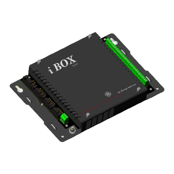
Carriers may not assume responsibility for damage after the customer accepts delivery. Unpacking Carefully remove the iBox from its shipping package. Visually inspect the unit to ensure it has not sustained any visible damage during transit. The figure below shows an iBox removed from the shipping package. - Page 21 GE Grid Solutions Installation and Maintenance Guide Unpacking and Inspection , Continued Part Numbers This table contains part numbers and descriptions for each iBox variant: Part Number iBox Description 505-0100 24 V Digital Input and 4 Trip/Close Control Outputs 505-0101...
-
Page 22: Storage
If you are storing a new iBox which has the battery “PULL” tab in place, you do not need to remove the battery for storage; the “PULL” tab disconnects (insulates) the battery function. -
Page 23: Installation Tools
Kit GE Grid Solutions Installation and Maintenance Guide 1.4. Installation Tools Tools for the Before beginning the installation procedure, ensure you have the following tools and equipment: • A Windows PC with HyperTerminal (or any Windows based terminal emulation software) loaded •... -
Page 24: Ibox Installation And Maintenance
Kit GE Grid Solutions Installation and Maintenance Guide Section 2: iBox Installation and Maintenance Overview Introduction This section covers the following topics: • Familiarization of the iBox Installing the iBox • • Configuring the iBox • Testing the iBox •... -
Page 25: Familiarization
(power connection), and a protective earth terminal. • Right side has a 28-position terminal block for field I/O, separable in pairs. Operation and You can operate and maintain the iBox configuration through the WESMAINT port. Maintenance Inputs/ The iBox provides the following: Outputs •... - Page 26 Installation and Maintenance Guide Continued on next page Familiarization , continued Control The iBox provides the following control outputs: Outputs • Four Trip/Close pairs, or two Trip/Close pairs and two Form A contacts. • Separate Master Trip and Master Close relays •...
-
Page 27: Installing The Ibox
Installation and Maintenance Guide 2.2. Installing the iBox Overview Safety Before beginning to install the iBox, thoroughly review the “Safety Precautions” for Precautions guidelines and warnings regarding the safe handling and installation of the product. Installation Installing the iBox involves the following main steps:... - Page 28 (windblown dust and dirt, for example) unless you install it in a secondary protective enclosure. Never operate an iBox in the field with the top cover removed. Operation with the top cover removed may alter product performance specifications, and result in component damage from foreign matter entry.
- Page 29 Installation and Maintenance Guide Installation Guidelines , continued Power Fusing Always replace fuses with the same type and rating used by GE Digital Energy. The fuse types and ratings are stated in “Fuse Replacement” on page 59. Always fuse-protect field power sources. Grounding...
- Page 30 Align the iBox in its proper position on a flat mounting surface. iBox Install and tighten the four screws, holding the iBox firmly in place on the mounting surface. Loosen the iBox top cover and remove the battery “PULL” tab. The iBox is delivered with this tab in place to insulate the battery during shipment.
- Page 31 The iBox’s power supply connection is a three-position terminal block located on the bottom left side of the iBox. This removable terminal block must be disconnected to turn off the power supply input. The iBox does not have an ON/OFF switch.
- Page 32 Once power is applied, the iBox automatically boots and conducts a series of self- Diagnostics diagnostic tests. If the iBox fails to boot up properly (which indicates that a self- diagnostic failure has occurred), it might have sustained internal damage during shipping.
- Page 33 GE Grid Solutions Installation and Maintenance Guide Connecting Serial Interfaces WESMAINT The iBox is equipped with a WESMAINT port. By attaching a WESMAINT cable Port between the WESMAINT port and your PC, the iBox can: • Provide local maintenance and diagnostic functionality •...
- Page 34 IRIG-B receivers are available with modulated and/or unmodulated output options. If Options the unmodulated output of the receiver is a coaxial connection, a converter will be required to interface to the iBox. COM Ports COM ports provide the following: •...
- Page 35 Radio Key Open Collector Output for COM Port 1 only (jumper selected with JP3 installed). 2-Wire RS-485 The following schematic shows the cable wiring necessary for 2-wire RS-485 Cable operation. iBox Connectors J2, J3 or J4 Description PIN # - TX / RX Data - Data -...
-
Page 36: Configuring Your Ibox
You can create a project for configuring your iBox device using SGConfig. Configuration A sample configuration is included on the CD with the iBox. You can create the Template iBox device configuration starting from the sample configuration or create a new configuration from scratch. - Page 37 Click SGConfig, > SGConfig. Project Result: SGConfig opens. Importing the Factory Configuration Click GE > Archive > Project > Restore. Click Restore. Result: The Restore Project Details window appears: Insert your configuration CD in the drive. Navigate to the configuration file in the Archive File Name field.
- Page 38 This procedure assumes that you are using the default firmware already loaded in the iBox or have created a firmware set. iBox Device When you create a new iBox device, select the iBox device template to see the Icon appropriate configuration screens.
- Page 39 Click Close to complete the creation of the new iBox device. The wizard closes. New Device After you complete these steps, an iBox icon, representing your new device, appears in the main proje Icon window. The new iBox device is now ready to be configured.
- Page 40 GE Grid Solutions Installation and Maintenance Guide Configuring Application Firmware The iBox uses the D25 Plant I/O Subsystem (P097) Data Collection Application to Overview configure the digital inputs. Configure the iBox Plant I/O before you configure the points in the System Point Database application.
- Page 41 Downloading your iBox Configuration Procedure: Step Action Downloading If you have not already done so, connect your PC to the iBox your iBox WESMAINT port and open SGConfig. Configuration In the SGConfig Project window, click the iBox device icon. Click Communications group > Connect > TeraTerm command.
- Page 42 Downloading On the SGConfig click Terminal Emulator Connectivity group, click your iBox Connect. Configuration Result: SGConfig connects to the iBox and the 68K Monitor command (continued) line appears. On the SGConfig click Terminal Emulator Actions menu, click Sync To Device.
- Page 43 Refer to Appendix F: Installing and Connecting DNP3 I/O Modules for installation and connection instructions. Use SGConfig to configure the DNP3 DCA in the iBox so that it communicates with your DNP3 I/O module. There are three tables to configure: •...
- Page 44 Installation and Maintenance Guide Configuring the iBox to work with a DNP3 I/O Module , continued For example, when configuring your iBox RTU Master to work with a DNP Example Digital Input Module, assume that you have a DNP Digital Input Module: Configuration •...
-
Page 45: Testing Your Ibox
In the event that you do not have a valid configuration file loaded into your iBox’s NVRAM, or the file becomes corrupted before the unit is installed, you must reload the file before performing these verification tests. - Page 46 GE Grid Solutions Installation and Maintenance Guide LED Descriptions Overview You can verify the iBox is operating properly by inspecting the LEDs on the iBox chassis. Description The iBox has the following LED indicators, all of which are GREEN. Location...
- Page 47 For further information about using WESMAINT software, refer to the WESMAINTII+ User’s Guide (Document Number B014-1UG). 68K Monitor The iBox’s 68K Monitor is a debugging and diagnostics tool that is accessible in two ways: • As a menu selection available through WESMAINT •...
- Page 48 Boot Test Verification System The iBox software includes a Power On Self-Test (POST) process, which runs when Diagnostics the unit is powered ON and determines whether or not the iBox circuitry is working (POST) properly. Terminal Terminal emulation software is not part of the iBox system, but you can use terminal ®...
- Page 49 Boot Up The iBox automatically boots as soon as the power is turned on. If the iBox fails to boot up, it may have sustained damage during shipping. Contact GE Digital Energy for assistance. 994-0047-5.10-4...
- Page 50 Note: If the Welcome banner does not appear, and only a <iBoxS prompt displays, a valid code or configuration file is not loaded into the iBox’s memory. Stop this procedure and refer to “Downloading Code Files” on page 65 for procedures for...
-
Page 51: Connecting And Testing Field Wiring
Kit GE Grid Solutions Installation and Maintenance Guide 2.5. Connecting and Testing Field Wiring Overview Introduction This section describes the process for making and testing field connections to the iBox. 994-0047-5.10-4 GE Information... - Page 52 DI is receiving a sufficient wetting voltage, the green LED associated with the DI will light. Digital Input The following table shows the iBox’s ON and OFF state thresholds. Verify that Thresholds inputs do not exceed the maximum overload voltage; otherwise, the iBox may be damaged.
- Page 53 Kit GE Grid Solutions Installation and Maintenance Guide Digital Input Configuration Digital Input Field wiring for all digital input variants are made through the iBox’s terminal Field blocks, separable in pairs. Connections Digital Input The digital input is wetted (or turned ON) by closing a contact across the two input Wetting termination points.
- Page 54 Kit GE Grid Solutions Installation and Maintenance Guide Digital Outputs Operating iBox control outputs have two modes of operation: Modes • Trip/Close (T/C) pairs • Digital Output (DO) isolation Form A contacts. Note: Using SGConfig, you must configure the digital outputs for four Trip/Close outputs or two Trip/Close and two digital outputs, depending on the part number.
- Page 55 “Boot Test Verification” on page 48. Note The quantity and relative position of data points in the iBox’s System Point Database is determined by the version of the iBox Plant I/O software application present in your iBox’s firmware.
- Page 56 Note The quantity and relative position of data points in the iBox’s System Point Database is determined by the version of the iBox Plant I/O software application present in the iBox’s firmware. You can determine the actual point number that you want to test by viewing the point descriptions in WESMAINT or in the SGConfig configuration tables for your iBox.
- Page 57 If relays do not operate: 1. Ensure that the CONTROLS enable jumper is in the REMOTE position. No error message appears in WESMAINT if the test fails 2. Reboot the iBox, and repeat the procedure 3. Call GE Digital Energy for assistance Repeat Test...
-
Page 58: Servicing Your Ibox
Installation and Maintenance Guide 2.6. Servicing your iBox Introduction This section provides information and procedures for maintaining the iBox. The iBox does not require any scheduled maintenance, other than periodic inspection to ensure that the: • Unit has sustained no accidental physical damage, •... - Page 59 Fuse Location The fuse is located in position F1 on the main board. To find the fuse, remove the iBox top cover, and look to the bottom left corner of the main board, close to the protective earth terminal. Procedure...
- Page 60 Battery The battery is located in position BT1 on the main board. To find the battery, remove Location the iBox top cover, and look to the bottom center-right of the main board, close to the column of relays. Battery Type The iBox uses a 3 V, BR2/3A, lithium battery, GE part number 980-0026.
-
Page 61: Maintaining Your Ibox Software
Kit GE Grid Solutions Installation and Maintenance Guide 2.7. Maintaining your iBox Software Overview Introduction The iBox is factory pre-configured and tested. It contains all required operating software, and is able to upload and download configuration files. 994-0047-5.10-4 GE Information... - Page 62 Background iBox operation requires two different files: • Code File: This file defines the applications that can be supported by the iBox. • Configuration File: This file, which is generated using SGConfig, is used to enable and configure the applications’ operating characteristics.
- Page 63 1. Every time the iBox reboots, a counter increments File Mismatch 2. If the iBox runs for two minutes without a reboot, the counter clears. 3. If the counter reaches 20, the base system invalidates the configuration and forces a system reset.
- Page 64 GE Grid Solutions Installation and Maintenance Guide Deleting Configuration Files Erase a configuration file from the iBox’s NVRAM before downloading a new code Erasing a file into FLASH memory, unless the code file is exactly the same as the one that was Configuration in use before the download.
- Page 65 If the iBox software program features need to be changed or upgraded, the existing flash memory can be erased, and new code downloaded. Programming There are three ways to program iBox flash memory (the one you use will depend on Flash Memory your system options and network type): •...
- Page 66 GE Grid Solutions Installation and Maintenance Guide Downloading Code Files , continued Serial Code You will need the following before you can download a code file into the iBox flash Download: memory: Requirements • Windows PC with HyperTerminal (or equivalent) communication software.
- Page 67 , continued Download Procedure, continued Note If the iBox does not have a code file loaded, or if it has detected a corrupt flash file, you will have to go directly to Step 8 and log directly into the monitor. Step...
- Page 68 If the transfer does not complete or it stalls, halt and restart the transfer. Download is Reboot the iBox, watching the display on the PC monitor. Note that the iBox Successful monitor speed returns to 9600 bps, if it was changed during the procedure.
-
Page 69: Troubleshooting Your Ibox
Kit GE Grid Solutions Installation and Maintenance Guide 2.8. Troubleshooting your iBox Overview Introduction This section provides instructions on what to do if the system malfunctions, or when error messages appear in WESMAINT. 994-0047-5.10-4 GE Information... - Page 70 Reboot the iBox. Press ENTER Result: A low-level error log displays. If these tables fail to help remedy the situation, or if you need help interpreting error messages, contact GE Digital Energy for assistance. Continued on next page 994-0047-5.10-4 GE Information...
- Page 71 Move the Controls Jumper Aborted position (JP2 is removed). to the Remote position (Install JP2). Active Requests The iBox Plant I/O Subsystem Verify coil status. Aborted monitoring detects a conflict between desired and actual coil status (a coil is not energized when it should be).
- Page 72 Kit GE Grid Solutions Installation and Maintenance Guide Runtime and Startup Errors, Continued Symptom Possible Causes Suggestions NVRAM Check Failure System start-up fails Use WESMAINT to view the error message, and refer to related configuration guide for suggestions. Application Checksum...
- Page 73 Kit GE Grid Solutions Installation and Maintenance Guide Initialization Errors Overview Several error situations, related to initialization, can occur with file transfers. The most common case will be that the configuration and code in the Boot File are those in the memory of the client causing the client to initialize immediately.
- Page 74 Kit GE Grid Solutions Installation and Maintenance Guide Errors Indicated by LEDs Overview The following errors are indicated by the LEDs: Symptom Possible Causes Suggestions Unit is not receiving power PWR LED does not Confirm that power light source is working...
-
Page 75: Replacing Your Ibox
Needed • Replacement iBox. Before Verify that the replacement iBox unit is fitted with the same options and connectors Installing as the original unit, before proceeding. Refer to “Product Identification” on page 20 for detailed information. Since hazardous voltages can cause shock, burns or death: •... - Page 76 Action iBox Removing the Existing iBox Power down the iBox by unplugging power from TB1. Disconnect ground from the iBox. Ensure no voltage or current is applied to any of the terminals on the iBox. Use a meter if necessary.
-
Page 77: Ibox Kit Installation And Maintenance
In addition to the iBox features, the 19” rack-mountable iBox Kit can be optioned to provide DC analog inputs AC analog inputs, an Ethernet connection, and support for a wide range of power supply input voltages. Examples of DC and AC iBox Kits are shown below. - Page 78 DC Analog Input Module (optional, eight DC analog inputs) • AC Analog Input Module (optional, 3 CT and 3 PT inputs) An example configuration of the iBox AC Kit is illustrated below (other options of the iBox Kit are equipped differently): AC Kit...
- Page 79 Maintenance connection. If you configure the iBox Kit to operate over a LAN, you can maintain the iBox configuration over the LAN or directly through the WESMAINT port. If you operate the iBox Kit through a serial connection, you can only maintain the iBox configuration through the WESMAINT port.
- Page 80 − Power Supply: 6 VA max Power Supply The power supply provides 24 VDC power to all iBox Kit components. It can also deliver limited 24 VDC power to customer-provided equipment. The power supply comes in two input voltage-range options: •...
- Page 81 Ethernet Module IP #1 and IP #3 are both accessible from the LAN. IP #2 is internal to the iBox Kit and is not accessible from the LAN. You set IP #2 and IP #3 when you configure the Ethernet Module. The Ethernet Module calculates IP #1 (equal to IP #2 + 1), and assigns this address to the iBox through PPP.
-
Page 82: Installing The Ibox Kit
GE Grid Solutions Installation and Maintenance Guide 3.2. Installing the iBox Kit Overview Safety Before beginning to install the iBox Kit, thoroughly review the “Safety Precautions” Precautions for guidelines and warnings regarding the safe handling and installation of the product. Installation... - Page 83 Physical Mounting Rack Spacing When mounting the iBox Kit in a rack with other equipment, leave at least one rack unit (RU) of space above and below the equipment to allow for cooling air flow and cable routing (1 RU = 1.75 inches or 44.5 mm).
- Page 84 Kit GE Grid Solutions Installation and Maintenance Guide Connections Ground Connect site ground to the iBox Kit protective earth terminal. We recommend 12 Connection AWG wire, a ring connector and a toothlock washer. iBox Kit (DC) Protective Earth Terminal...
- Page 85 GE Grid Solutions Installation and Maintenance Guide Communications Cabling Communi- If your iBox is equipped with an Ethernet module, connect the LAN to the iBox by cations plugging a CAT5 cable equipped with an RJ45 connector into the Ethernet module: Cabling -...
- Page 86 Kit GE Grid Solutions Installation and Maintenance Guide Communications Cabling , continued Communic- As necessary, connect the appropriate iBox COM port to your equipment using serial ations cables with male DB-9 connectors: Cabling - Serial WESMAINT COM 1 COM 2...
-
Page 87: Configuring The Ibox Kit Components
Installation and Maintenance Guide 3.3. Configuring the iBox Kit Components Introduction Your iBox Kit modules have been pre-configured based on your order. However, you need to configure, or confirm the configuration of, the following items: iBox Kit Module Configurable Settings iBox •... - Page 88 SGConfig installed on your PC. • Serial number of your iBox, from the iBox circuit board To configure an iBox Kit with a LAN connection, you will need, in addition to the above: • IP address/subnet mask of the LAN, iBox and Ethernet Module •...
- Page 89 GE Grid Solutions Installation and Maintenance Guide Configuring and Testing your iBox Kit Components , continued Configuration The procedures for configuring an iBox Kit with a serial connection are as follows: Procedures – • Restoring your SGConfig Project on page 91 Serial Connection •...
- Page 90 Options for LAN Connection Note: The first time you configure the iBox in an iBox Kit, you will do it through the WESMAINT serial port. Once you have configured the iBox, you will be able to download subsequent configurations over the LAN.
-
Page 91: Restoring Your Sgconfig Project
Result: The configuration file uploads to your PC, and your project appears in an SGConfig project tab. Next Step If you are operating the iBox Kit through a serial connection, the next step is: • Configuring Project Properties - Serial on page 92 If you are operating the iBox Kit through a LAN connection, the next step is: •... -
Page 92: Configuring Project Properties - Serial
Use the following procedure to configure Project Properties if you are operating the iBox Kit through a serial connection. Procedure: Step Action Configuring In SGConfig, click GE > Project > Properties. Project Result: The Select Project window appears: Properties - Serial Select your project under SGConfig Projects and click OK. - Page 93 Click GE > Copy Project. [continued] Result: The Copy Project window appears: Type in a New Project Name for your project. Click OK to save. Next Step The next step is: • Configuring iBox Device Properties - Serial on page 94 994-0047-5.10-4 GE Information...
-
Page 94: Configuring Ibox Device Properties - Serial
Configuring iBox Device Properties - Serial Procedure: Refer to “iBox Device Properties” on page 36 for instructions on configuring iBox Configuring Device Properties, when you are connecting to the iBox Kit through a serial port. iBox Device Properties - Serial... -
Page 95: Configuring Ibox Communications Options - Serial
Kit GE Grid Solutions Installation and Maintenance Guide Configuring iBox Communications Options - Serial Introduction Use the following procedure to configure iBox Communications Options if you are operating the iBox Kit through a serial connection. Procedure: Step Action Configuring In the Project tab area, right-click the iBox device icon. -
Page 96: Configuring The Application Firmware
Application Firmware Next Step If you are operating the iBox Kit through a serial connection, the next step is: • Downloading your iBox Configuration - Serial on page 97 If you are operating the iBox Kit through a LAN connection, the next step is: •... -
Page 97: Downloading Your Ibox Configuration - Serial
If your iBox Kit is equipped with an AC Analog Input Module, the next step is: • Configuring the AC Analog Module on page 130 If your iBox Kit is not equipped with a DC or AC Analog Input Module, the next step is: •... - Page 98 Kit GE Grid Solutions Installation and Maintenance Guide Configuring Project Properties - LAN Introduction Use the following procedure to configure Project Properties if you are operating the iBox Kit through a LAN connection. 994-0047-5.10-4 GE Information...
- Page 99 Installation and Maintenance Guide Procedure: Step Action Configuring In SGConfig, click GE > Project > Properties. Project Result: The Select Project window appears: Properties - Select your project under SGConfig Projects and click OK. Result: The Project Properties window appears: Continued on next page 994-0047-5.10-4...
- Page 100 Note: Even if your LAN has a default gateway, you do not need to enter it here. Click OK to save. Next Step The next step is: • Configuring iBox Device Properties - LAN on page 101 994-0047-5.10-4 GE Information...
- Page 101 Result: The iBOX Device Wizard appears. Verify LAN based device is selected. In the Description box, type in a name for the iBox. In the Serial Number box, type i the serial number of the iBox. Continued on next page 994-0047-5.10-4...
- Page 102 Action Configuring Click the Processor tab. Device Properties On the Memory Model tab, ensure that Derive From iBox Hardware - LAN Setting is selected. [continued] Confirm the settings are as shown above, and modify them if they are not. Click the LAN Settings tab, and then click the General tab.
- Page 103 ® corresponding changes to the Digi One Ethernet Module, if equipped, or to the equipment to which the iBox Ethernet port is connected. See “Configuring the Ethernet Module” on page 109. Close the PPP Driver window. Click Yes to save your changes.
- Page 104 Kit GE Grid Solutions Installation and Maintenance Guide Configuring the iBox PPP Driver and Internet Data Links , continued Procedure: Step Action Configuring On the Data Translation Applications tab, double-click the DNP the PPP Internet Data Link icon. Driver...
- Page 105 Kit GE Grid Solutions Installation and Maintenance Guide Configuring iBox Communications Options - LAN Introduction Use the following procedure to configure iBox Communications Options if you are operating the iBox Kit through a LAN connection. 994-0047-5.10-4 GE Information...
- Page 106 GE Grid Solutions Installation and Maintenance Guide Procedure: Step Action Configuring In the Project window, right-click the iBox device icon, click Communi- Communications, and then click Options. cations Options - LAN On the Interface tab, click iSCS LAN and LAN A.
- Page 107 Click the Communications tab, then click the LAN tab. In LAN A, select from the list the source IP address that you will use to communicate with the iBox Kit over the LAN. Click OK. Next Step The next step is: •...
- Page 108 GE Grid Solutions Installation and Maintenance Guide Downloading your iBox Configuration - LAN Introduction The first time you configure your iBox, you will need to connect your PC to the iBox WESMAINT port, as shown below: PC running SGConfig iBOX Kit...
- Page 109 Kit GE Grid Solutions Installation and Maintenance Guide Configuring the Ethernet Module Introduction The following procedure describes the configuration of the Digi One IAP Ethernet Module. Procedure: You need to set the Digi One Ethernet and PPP IP addresses. Refer to “IP Configuring Addressing”...
- Page 110 Kit GE Grid Solutions Installation and Maintenance Guide Configuring the Ethernet Module , continued Procedure: Step Action Configuring Configuring your PC’s Proxy Settings (Windows 2000) the Digi One (continued) If your PC is configured to use a proxy server, follow the procedure below to add the Digi One IP address to Exceptions so you can browse directly into the Digi One Web server.
- Page 111 Kit GE Grid Solutions Installation and Maintenance Guide Configuring the Ethernet Module , continued Procedure: Step Action Configuring In Exceptions, add the default Digi One Ethernet IP address, the Digi One 192.168.1.100. (continued) Note: You can use the wildcard character (*) to specify a range of IP addresses;...
- Page 112 Example: In the following example, the PPP IP address is set to 192.168.1.19: set user name=”link1” localipaddr=192.168.1.19 netrouting=off In this example, the iBox IP address will automatically be set to 192.168.1.20 (192.168.1.19 + 1) over PPP. Save the modified configuration file as DigiDefaultConfig_Modified.txt.
- Page 113 Kit GE Grid Solutions Installation and Maintenance Guide Configuring the Ethernet Module , continued Procedure: Step Action Configuring Starting the Digi Device Setup Wizard the Digi One (continued) Insert the Digi Software and Documentation CD in your CD ROM drive.
- Page 114 Kit GE Grid Solutions Installation and Maintenance Guide Configuring the Ethernet Module , continued Procedure: Step Action Configuring Select your device. the Digi One Note: The MAC address of your Digi One IAP is located on the white (continued) label on the bottom or back of the device.
- Page 115 Kit GE Grid Solutions Installation and Maintenance Guide Configuring the Ethernet Module , continued Procedure: Step Action Configuring Click Next. the Digi One (continued) Result: The Select Scenario page appears: Downloading the Configuration to the Digi One In the drop-down list under Scenario List, select Custom Configuration.
- Page 116 Kit GE Grid Solutions Installation and Maintenance Guide Configuring the Ethernet Module , continued Procedure: Step Action Configuring Click Next. the Digi One (continued) Result: The Verify Configuration page appears: Continued on next page 994-0047-5.10-4 GE Information...
- Page 117 Kit GE Grid Solutions Installation and Maintenance Guide Configuring the Ethernet Module , continued Procedure: Step Action Configuring Do one of the following: the Digi One (continued) • If the configuration parameters are not correct, click Back and make the necessary corrections.
- Page 118 Kit GE Grid Solutions Installation and Maintenance Guide Configuring the Ethernet Module , continued Procedure: Step Action Configuring Connecting to the Digi One Web Server the Digi One (continued) When the reboot completes, the Saved configuration successfully screen appears: Make sure Register my Digi One IAP on the Digi website is not selected, and click Finish.
- Page 119 Kit GE Grid Solutions Installation and Maintenance Guide Configuring the Ethernet Module , continued Procedure: Step Action Configuring Enter User Name root and Password dbps and click OK. the Digi One (continued) Result: The Digi One IAP Configuration and Management home...
- Page 120 Kit GE Grid Solutions Installation and Maintenance Guide Configuring the Ethernet Module , continued Procedure: Step Action Configuring Downloading the Configuration File to the Digi One the Digi One (continued) Under Administration, click Backup/Restore. Result: The Backup/Restore page appears: Click Browse and enter the location of the Digi One configuration file on your PC.
- Page 121 Kit GE Grid Solutions Installation and Maintenance Guide Configuring the Ethernet Module , continued Procedure: Step Action Configuring To confirm that it is correctly configured, ping the Digi One through the the Digi One DOS command line. (continued) Under Configuration, click Security.
- Page 122 If your iBox Kit is equipped with a DC Analog Input Module, the next step is: • Configuring the DC Analog Module on page 123 If your iBox Kit is not equipped with a DC Analog Input Module, the next step is: • Testing the iBox Kit on page 131 994-0047-5.10-4...
- Page 123 The following procedure is intended as a high-level overview. For detailed instructions and settings, refer to the following documents: • ADAM 4000 Data Acquisition Modules User’s Manual – Available from the Advantech CD that shipped with your iBox Kit (accessible through Manual > ADAM 4000 > ADAM-4000.pdf) ® •...
- Page 124 Step Action Power down the iBox Kit. Disconnect the cable between the ADAM-4017+ and iBox COM2, at the ADAM-4017+ end. Connect the RS-485 side of the RS-485/RS-232 converter to the DATA+ and DATA- terminals on the ADAM-4017+. Connect the RS-232 side of the converter to one of your PC’s COM ports.
- Page 125 Kit GE Grid Solutions Installation and Maintenance Guide Configuring the DC Analog Module , continued Procedure: Step Action Configuring Install the ADAM-4000 utility from the Advantech CD (accessible the ADAM- through Install Products > ADAM-4000 Utility). 4017+ (continued) Open the ADAM-4000 Utility:...
- Page 126 Kit GE Grid Solutions Installation and Maintenance Guide Configuring the DC Analog Module , continued Procedure: Step Action Configuring In the left-hand pane, select the COM port to which the ADAM-4017+ is the ADAM- 4017+ connected, and click Search ( ) in the toolbar.
- Page 127 For detailed instructions and settings, refer to the ADAM 4000 Data Acquisition Modules User’s Manual – Available from the Advantech CD that shipped with your iBox (accessible through Manual > ADAM 4000 > ADAM-4000.pdf) Continued on next page 994-0047-5.10-4...
- Page 128 DC analog inputs. Descriptors Step Action Open the iBox Kit device in SGConfig, open the Applications List, and click the System Point Database Applications tab. Double-click the System Point Database icon. Result: The System Point Database Properties window displays.
- Page 129 If your iBox Kit is equipped with a AC Analog Input Module, the next step is: • Configuring the AC Analog Module on page 130 If your iBox Kit is not equipped with a AC Analog Input Module, the next step is: • Testing the iBox Kit on page 131 994-0047-5.10-4...
- Page 130 AC analog inputs. Descriptors Step Action Open the iBox Kit device in SGConfig, open the Applications List, and click the System Point Database Applications tab. Double-click the System Point Database icon. Result: The System Point Database Properties window displays.
- Page 131 Pinging the If the iBox Kit modules are operating correctly, and it is configured for LAN Ethernet and connection, you will be able to ping the Ethernet Module and iBox IP addresses from iBox your PC. 994-0047-5.10-4...
-
Page 132: Connecting Field Wiring
Testing Field Wiring” on page 51 for information on how to connect field wiring to the iBox, and how to map and test these connections. AC Analog AC analog inputs are connected to the iBox Kit through the AC Analog Input Inputs module, as shown below:... - Page 133 Kit GE Grid Solutions Installation and Maintenance Guide Connecting Field Wiring , continued DC Analog DC analog inputs are connected to the iBox Kit through the DC Analog Input Inputs module, as shown below: Vin 5+ Vin 4- Vin 5-...
-
Page 134: Servicing Your Ibox Kit
Location of fuses • Updating your iBox configuration Procedure: For instructions on how to service the iBox, refer to “Servicing your iBox” on page Servicing the iBox Connections The other modules in the iBox Kit require very little servicing. Verify that connections are tight, and LEDs are operating correctly. -
Page 135: Maintaining Your Ibox Kit Software
The iBox software may need occasional maintenance. Although other modules may also contain firmware, this firmware will typically not need to be upgraded. Maintaining For information about your iBox software and instructions on how to maintain it, your iBox refer to “Maintaining your iBox Software” on page 61. - Page 136 Downloading your iBox Configuration over the LAN Introduction Once you have configured the iBox PPP Driver and Ethernet Module, you can download subsequent changes to the iBox configuration over the LAN. To do this, configure your PC with an IP address in the LAN’s subnet. This is illustrated below:...
- Page 137 Result: SGConfig downloads the new configuration to the iBox. SGConfig displays progress messages until the new configuration has been successfully downloaded. Note: The iBox does not need to be rebooted for the new configuration to be effective. Exit SGConfig. 994-0047-5.10-4...
-
Page 138: Troubleshooting Your Ibox Kit
3.7. Troubleshooting your iBox Kit Overview The LED indicators on each iBox Kit device can be used to troubleshoot most iBox Kit problems. If device configuration files are those supplied with the iBox Kit, most problems are the result of failed cabling or connection. -
Page 139: Replacing Your Ibox Kit
Fully unscrew the lower mounting screws. Loosen the upper mounting screws, then raise and remove the iBox Kit from the rack. Check the jumpers and settings on the replacement iBox Kit and make sure they are the same as those on the failed unit. -
Page 140: Removing Configuration Data And Sensitive Information
In the event that it is necessary to remove the configuration data and sensitive information from the iBox (for example, the iBox is being disposed of or being returned for maintenance [i.e., RMA]), this section provides the data removal procedure. -
Page 141: From The Pc Running Configuration Software
Installation and Maintenance Guide 4.2. From the PC Running Configuration Software Method If SGConfig have been used to configure the iBox processor, configuration data resides on the data storage media (e.g., hard drives, memory cards, etc.) of the PC running SGConfig. - Page 142 Kit GE Grid Solutions Installation and Maintenance Guide 994-0047-5.10-4 GE Information...
-
Page 143: Appendix A: Technical Specifications
Kit GE Grid Solutions Installation and Maintenance Guide Appendix A: Technical Specifications iBox Power Power Supply Input Options 20-60 Vdc Requirements Power Consumption 7 Watts (maximum) Inrush Current Less than 0.5A peak Power Supply Protection Input fuse Reverse polarity protection provided... - Page 144 Kit GE Grid Solutions Installation and Maintenance Guide Technical Specifications – iBox , continued Digital General Up to four relay outputs: 4 Trip/Close pairs or 2 Trip/Close pairs and 2 Form A contacts Outputs Security features Separate Master Trip and Master Close relays Single point of failure integrity, select-before- operate (SBO) functionality.
- Page 145 Kit GE Grid Solutions Installation and Maintenance Guide Technical Specifications – iBox , continued EMI/EMC CISPR11 Limits and methods of measurement of electromagnetic disturbance characteristics of Compliance industrial, scientific and medical (ISM) radio- frequency equipment. EN61000-4-2 Immunity Test EN61000-4-3...
- Page 146 8.75” high x 19” wide x 2” deep Dimensions (22.23 cm high x 48.26 cm wide x 5.08 cm deep) 19” rack mounting Mounting iBox: -40° to +80°C DC Analog Module: -10° to +70°C Operational AC Analog Module: -20° to +70°C Temperature Ethernet Module: 0°...
- Page 147 Kit GE Grid Solutions Installation and Maintenance Guide Technical Specifications – iBox Kit , continued Digital Inputs Up to eight bipolar optically isolated (2000 V General 250 V rated compression termination consisting of a header and removable plugs suitable for 12 – 24 AWG Physical wire 0.01A/150V...
- Page 148 Kit GE Grid Solutions Installation and Maintenance Guide Technical Specifications – iBox Kit , continued AC Analog , Phase Angle, Frequency, Power Factor, Real Analog Input Options Inputs Power (W), Reactive Power (VAR), Apparent Power (VA), Watt-Hour (optional) Nominal PT Input Range...
-
Page 149: Appendix B: Ibox Kit Default Configurations
Kit GE Grid Solutions Installation and Maintenance Guide Appendix B: iBox Kit Default Configurations When shipped as part of an iBox Kit, the iBox COM port default configurations are set to one of the following: iBox (IBOX-BSC Configuration Details Comments iBox DNP 3.0 Master Address: 10... - Page 150 Communication Type: RS-232 User Name: westronic WESMAINT Password: rd Control Password: control Note: COM3 is used to connect the AC analog input module to the iBox. IBOX Kit with DC Analogs (IBOX-DCA) Configuration Details Comments iBox DNP 3.0 Master Address: 10 Refer to point map tables for more detail.
- Page 151 Slave IP Address: 192.168.1.20 Subnet Mask: 255.255.255.0 User Name: westronic WESMAINT Password: rd Control Password: control Note: COM2 is used to connect to the Ethernet Module via PPP/TCP/IP. Note: COM3 is used to connect the AC Module to the iBox. 994-0047-5.10-4 GE Information...
- Page 152 -32768 Zero input Maximum positive input 32767 However, for the 4-20 mA input, the following values are returned by the iBox to the master: Input Value Value Returned to Master Any input in the range of 0 to 4 mA...
-
Page 153: Appendix C: Resetting The Digi One Configuration
Kit GE Grid Solutions Installation and Maintenance Guide Appendix C: Resetting the Digi One Configuration You can restore your Digi One configuration to the factory default configuration, as follows: Procedure: Step Action Resetting the Turn off power to the Digi One. - Page 154 Kit GE Grid Solutions Installation and Maintenance Guide 994-0047-5.10-4 GE Information...
-
Page 155: Appendix D: Setting Your Pc Ip Address
Select Internet Protocol (TCP/IP). Click Properties. Select Use the following IP address, Enter an IP address that is in the same subnet as the iBox, but not used by any other devices. Enter the same subnet mask as the iBox. Click OK. - Page 156 Kit GE Grid Solutions Installation and Maintenance Guide 994-0047-5.10-4 GE Information...
-
Page 157: Appendix E: Dpa Default Point Mapping
Installation and Maintenance Guide Appendix E: DPA Default Point Mapping For point mapping of individual standard iBox kits, please look in the Source column of the table below. Point mapping corresponding to Plant I/O applies to all types of standard iBox kits. - Page 158 Kit GE Grid Solutions Installation and Maintenance Guide COM1 COM2 MODBUS DCA Data Source Register Point Description DNP DPA MODBUS DPA DNP TCP/IP Type Address Point Point Address DPA Point ADAM-4017 AI CH: 00 ADAM-4017 AI CH: 01 ADAM-4017 AI CH: 02...
- Page 159 Kit GE Grid Solutions Installation and Maintenance Guide COM1 COM2 MODBUS DCA Data Source Register Point Description DNP DPA MODBUS DPA DNP TCP/IP Type Address Point Point Address DPA Point WATT PHASE B INST WATT PHASE C INST VAR PHASE A INST...
- Page 160 Kit GE Grid Solutions Installation and Maintenance Guide COM1 COM2 Data MODBUS DCA Source Point Description DNP DPA MODBUS DPA DNP TCP/IP Type Register Address Point Point Address DPA Point VA PHASE A AVG VA PHASE B AVG VA PHASE C AVG...
- Page 161 Kit GE Grid Solutions Installation and Maintenance Guide COM1 COM2 MODBUS DCA Data Source Register Point Description DNP DPA MODBUS DPA DNP TCP/IP Type Address Point Point Address DPA Point VAR MIN VA MIN PF MIN FREQ MIN 1282...
- Page 162 Kit GE Grid Solutions Installation and Maintenance Guide 994-0047-5.10-4 GE Information...
-
Page 163: Appendix F: Installing And Connecting Dnp3 I/O Modules
To install and connect DNP3 I/O modules: 1. Configure the DNP3 DCA in the iBox so that it communicates with your DNP3 I/O module. Refer to section: Configuring the iBox to work with a DNP3 I/O Module on page 43. - Page 164 Kit GE Grid Solutions Installation and Maintenance Guide Installing DNP3 I/O Modules in a Rack Rack Spacing When mounting multiple DNP3 I/O modules in a rack, or when mounting DNP3 I/O modules in a rack with other equipment , verify that there is at least one rack unit (RU) of space above and below the DNP03 I/O module to allow for cooling air flow and cable routing (1 RU = 1.75 inches or 44.5 mm).
- Page 165 Kit GE Grid Solutions Installation and Maintenance Guide Connecting to Protective Ground Connect your DNP3 I/O module to site ground, using a separate 2.05 mm (12 AWG) Yellow/ Green wire. Each type of DNP I/O Module has a different ground point, as shown in the examples below.
- Page 166 Connect the power supply to the last DNP3 I/O module in the chain. The cable from J2 on the last DNP3 I/O module to the power source (GE part number 977-0500) provides the connections shown in the following wiring diagram.
- Page 167 2. Connect pins 1 and 2 (and also pins 3 and 4 if a redundant power supply is used) on TB2 to an External Power Supply (40 to 150 VDC) as shown below: To iBox (RTU Master) To Ext Power...
- Page 168 Installation and Maintenance Guide Connecting to a iBox The cable from an iBox RTU Master to the first DNP I/O Module (GE Part Number 977-0502) has the following connections and jumpers: Note: Make sure the iBox RTU Master is configured for RS-485, 2W mode.
- Page 169 Kit GE Grid Solutions Installation and Maintenance Guide Appendix G: Error Messages When processing an output request, the Plant I/O Subsystem (P097) DCA may not be able to execute the request. If this occurs, the Plant I/O Subsystem DCA will set the status code returned with the request to the appropriate error code, and negatively acknowledge (NACK) the control request.
- Page 170 Kit GE Grid Solutions Installation and Maintenance Guide Online Configuration Wev List Not Available The WEV (WIN event) list request is not available. (0x001D) Online Configuration Out of Timers (0x001E) Lacked timed event buffers Online Configuration Sendx Fail (0x001F) Message send failed 994-0047-5.10-4...
- Page 171 Added Appendix F: Installing and Connecting DNP3 I/O Modules Sep 11, 2014 Fixed links. May 15, 2017 Replaced references to ConfigPro with SGConfig. Updated GE branding and contact information. Added information on battery “PULL” tab removal during iBox installation. AUTHENTICATION RECORD VERSION REV. DATE...
Need help?
Do you have a question about the iBox and is the answer not in the manual?
Questions and answers