Table of Contents
Advertisement
INSTALLATION AND OPERATION
SX TRANSISTOR CONTROL
Note: The information
to assist OEM's, Dealers and
the application, installation and service of GE solid-state controllers. This manual does not purport to cover all
variations in OEM vehicle types. Nor does it provide for every possible contingency to be met involving vehicle
installation, operation or maintenance. For additional information and/or problem resolution, please refer the matter to
the OEM vehicle manufacturer through his normal field service channels. Do not contact GE directly for this
assistance.
Section 1.0
INTRODUCTION .................................................................................................................. 3
1.1
1.2
1.3
1.4
Section 2.0
FEATURES OF SX FAMILY OF MOTOR CONTROLLERS ............................................... 4
2.1
2.1.1
2.1.2
2.1.3
2.1.4
2.1.5
2.1.6
2.2
2.2.1
SEPARATELY EXCITED (SX) TRANSISTORIZED MOTOR
FOR NEIGHBORHOOD ELECTRIC VEHICLE APPLICATIONS
INSTALLATION AND OPERATION MANUAL
General Electric Company October 2005
Table of Contents
Motor Characteristics ........................................................................................ 3
Solid-State Reversing ........................................................................................ 4
Flexible System Application ............................................................................... 4
More Features with Fewer Components ........................................................... 4
Performance ...................................................................................................... 4
Oscillator Card Features ............................................................................. 4
Standard Operation..................................................................................... 4
Control Acceleration ................................................................................... 5
Current Limit ............................................................................................... 5
Regenerative Braking to Base Speed ......................................................... 5
Auxiliary Speed Control ............................................................................... 5
Field Weakening......................................................................................... 5
Speed Limits .............................................................................................. 5
Top Speed Regulation .................................................................................5
Ramp Start .................................................................................................. 5
On-Board Coil Drivers and Internal Coil Suppression ................................ 6
System Protective Override ............................................................................... 6
Static Return to Off (SRO) ......................................................................... 6
CONTROLLERS
GE MODEL IC3645SR7A353T4
Page 1
contained herein is intended
Users of electric vehicles in
Updated Sept 2019
Advertisement
Table of Contents
Troubleshooting

Subscribe to Our Youtube Channel
Related Manuals for GE IC3645SR7A353T4


Summary of Contents for GE IC3645SR7A353T4
-
Page 1: Table Of Contents
Users of electric vehicles in the application, installation and service of GE solid-state controllers. This manual does not purport to cover all variations in OEM vehicle types. Nor does it provide for every possible contingency to be met involving vehicle installation, operation or maintenance. - Page 2 INSTALLATION AND OPERATION SX TRANSISTOR CONTROL Page 2 Table of Contents ( Continued ) 2.2.2 Accelerator Volts Hold Off ................6 2.2.3 Pulse Monitor Trip (PMT) ................6 2.2.4 Thermal Protector (TP)................6 2.2.5 Low Voltage ....................6 Diagnostics..........
-
Page 3: Introduction
GE has introduced a second generation system using separately excited DC shunt wound motors. The separately excited DC motor system... -
Page 4: Solid-State Reversing
12KHZ to 15KHZ, a frequency range normally above human For GE, the future is now, as we make available a new hearing. This high frequency, coupled with the elimination generation of electric traction motor systems for electric... -
Page 5: Control Acceleration
Section 2.1.2 Current Limit This feature requires a system tachometer. The standard GE system tach is built into the motor and provides four This circuit monitors motor current by utilizing sensors in pulses per armature revolution. Once the control has been series with the armature and field windings. -
Page 6: On-Board Coil Drivers And Internal Coil Suppression
BASIC OPERATION AND FEATURES SX TRANSISTOR CONTROL Page 6 Section 2.1.6 On-Board Coil Drivers and Internal Coil operate improperly, however, the resulting PMT should open the Line contactor, in the event of a failure. Suppression Section 2.3 Diagnostics A coil driver for the LINE contactor is on-board the control card. -
Page 7: Rs-232 Communication Port
BASIC OPERATION AND FEATURES SX TRANSISTOR CONTROL Page 7 Section 2.3.3 RS 232 Communication Port This serial communication port can be used with Interactive Custom Dash Displays to allow changes to vehicle operating parameters by the operator. Or, it can be used by service personnel to dump control operating information and settings into a personal computer program. -
Page 8: Ordering Information, Elementary And Outline Drawings
OUTLINE DRAWINGS, ELEMENTARY DRAWINGS AND INPUTS/OUTPUTS SX TRANSISTOR CONTROL Page 8 Section 3.0 ORDERING INFORMATION, ELEMENTARY AND OUTLINE DRAWINGS Section 3.1 Ordering Information for Separately Excited Controls Example: Part Number: IC3645 Argument Number: Argument 01: Basic Electric Vehicle Control Number Argument 02: Control Type: Separately Excited Control ( Plugging ) -
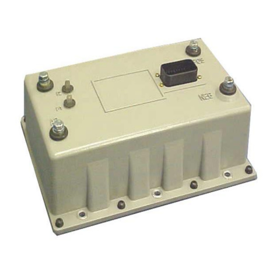
Page 9: Outline: Sx-2 Package Size
OUTLINE DRAWINGS, ELEMENTARY DRAWINGS AND INPUTS/OUTPUTS SX TRANSISTOR CONTROL Page 9 Section 3.2 Outline: Package Size Updated Sept 2019... -
Page 10: Standard Elementary For Neighborhood Electric Vehicle Application
OUTLINE DRAWINGS, ELEMENTARY DRAWINGS AND INPUTS/OUTPUTS SX TRANSISTOR CONTROL Page 10 Section 3.3 Standard Elementary for Neighborhood Electric Vehicle Application FUSE Updated Sept 2019... -
Page 11: Standard Neighborhood Electric Vehicle Application Input/Output List
OUTLINE DRAWINGS, ELEMENTARY DRAWINGS AND INPUTS/OUTPUTS SX TRANSISTOR CONTROL Page 11 Section 3.4 Neighborhood Electric Vehicle Application Input/Output List PIN MAIN PLUG INPUT/OUTPUT DESCRIPTION BATTERY VOLTS POS FROM KEY BATTERY VOLTS POS FROM KEY BATTERY NEG FROM ACCELERATOR START SWITCH BATTERY VOLTS POS FROM FORWARD SWITCH BATTERY VOLTS POS FROM REVERSE SWITCH BATTERY VOLTS POS FROM TURF SPEED LIMIT SWITCH... -
Page 12: Troubleshooting And Diagnostic Status Codes
The transistor control, like all electrical apparatus, does have some thermal losses. The semiconductor junctions GE does not recommend that any type of welding be have finite temperature limits, above which these devices performed on the vehicle after the installation of the may be damaged. -
Page 13: High Level Signals (Level H)
INSTALLATION AND OPERATION SX TRANSISTOR CONTROL Page 13 above. Intermixing cannot be allowed, unless noted Dash display cabling by exception. RS-232 cabling Interconnecting wire runs should carry a level designation. Note: Signal inputs to analog and digital blocks should be ... -
Page 14: Recommended Lubrication Of Pins And Sockets Prior To Installation
EV100/EV200 and Gen II products. Any connection made by GE to the A, B, X, Y, or Z plugs, includes the lubricant NYE 760G to prevent fretting of these connections during vehicle operation. -
Page 15: General Troubleshooting Instructions
INSTALLATION AND OPERATION SX TRANSISTOR CONTROL Page 15 Section 4.4 General Troubleshooting Instructions Check resistance on R x 1000 scale from frame to power and control terminals. A resistance of less than 20,000 Trouble-shooting the ZX family of controls should be quick ohms can cause misleading symptoms. -
Page 16: Traction Controller Status Codes
INSTALLATION AND OPERATION SX TRANSISTOR CONTROL Page 16 Section 4.5 Traction Control Codes TRACTION DESCRIPTION OF STATUS CAUSE OF STATUS INDICATION STATUS CODE Start switch fails to close. This status code will be displayed when the accelerator voltage at P7 is >1.4V, with the start switch open (P3 >... - Page 17 INSTALLATION AND OPERATION SX TRANSISTOR CONTROL Page 17 TRACTION DESCRIPTION OF STATUS CAUSE OF STATUS INDICATION STATUS CODE Accelerator voltage input is too high on This status code will be displayed when the power up after initial key switch accelerator input voltage at P7 >0.9V when the closure.
- Page 18 INSTALLATION AND OPERATION SX TRANSISTOR CONTROL Page 18 TRACTION DESCRIPTION OF STATUS CAUSE OF STATUS INDICATION STATUS CODE Start switch closed on power up after initial This status code will be displayed when P3 is key switch closure. less than 2.5 volts when the key switch is closed.
- Page 19 INSTALLATION AND OPERATION SX TRANSISTOR CONTROL Page 19 TRACTION DESCRIPTION OF STATUS CAUSE OF STATUS INDICATION STATUS CODE Battery voltage is too low at initial key switch This status code will be displayed when the closure. battery volts are less than 68.3 volts at initial key switch on.
- Page 20 INSTALLATION AND OPERATION SX TRANSISTOR CONTROL Page 20 TRACTION DESCRIPTION OF STATUS CAUSE OF STATUS INDICATION STATUS CODE Accelerator voltage is too high. This status code will be displayed when the accelerator voltage at P7 is greater than 4.5 volts. MEMORY RECALL CORRECTIVE ACTIONS TROUBLE-SHOOTING DIAGRAM...
- Page 21 INSTALLATION AND OPERATION SX TRANSISTOR CONTROL Page 21 TRACTION DESCRIPTION OF STATUS CAUSE OF STATUS INDICATION STATUS CODE Motor field current is too high when the This status code will be displayed when the current key switch is turned on. draw in the motor field is too high on start up.
- Page 22 (Values of less than 1.5 V at the thermal protector are typically indicative of a failed control.) GE Sentry for Windows software can be used to monitor control operation, and it will display a value for the thermal protector that is greater than 84 (corresponding to 1.65V), triggering this...
- Page 23 Traction Defective control. Controller Replace controller unit. GE Sentry for Windows software can be used to monitor control operation, and it will display a value for the motor amps that is less than 123 (corresponding to 2.4V), triggering this status code.
- Page 24 INSTALLATION AND OPERATION SX TRANSISTOR CONTROL Page 24 TRACTION DESCRIPTION OF STATUS CAUSE OF STATUS INDICATION STATUS CODE Armature transistor did not turn on This status code will be displayed when, during properly. control operation, the armature transistor fails to turn on properly.
- Page 25 INSTALLATION AND OPERATION SX TRANSISTOR CONTROL Page 25 TRACTION DESCRIPTION OF STATUS CAUSE OF STATUS INDICATION STATUS CODE Motor field current is too low during the This status code will be displayed when the current run mode. draw in the motor field is less than 1.3 amps and armature current is greater than 100 amps for more than 1.27 seconds during the run mode.
- Page 26 INSTALLATION AND OPERATION SX TRANSISTOR CONTROL Page 26 TRACTION DESCRIPTION OF STATUS CAUSE OF STATUS INDICATION STATUS CODE Controller “motor current sensor” input This status code will be displayed when the voltage is too low during running. input from the current sensor is too low (less than 1.0V, 416 amps) during running.
- Page 27 INSTALLATION AND OPERATION SX TRANSISTOR CONTROL Page 27 TRACTION DESCRIPTION OF CAUSE OF STATUS INDICATION STATUS CODE STATUS The line coil current is too high This status code will be displayed when the current limit in the during the run mode line coil is exceeded during the run mode.
- Page 28 INSTALLATION AND OPERATION SX TRANSISTOR CONTROL Page 28 TRACTION DESCRIPTION OF STATUS CAUSE OF STATUS INDICATION STATUS CODE Capacitor (1C) voltage too high during This status code will be displayed when the voltage at pedal up regen braking. 1C exceeds 96 volts during the regenerative braking cycle.
- Page 29 INSTALLATION AND OPERATION SX TRANSISTOR CONTROL Page 29 TRACTION DESCRIPTION OF STATUS CAUSE OF STATUS INDICATION STATUS CODE No tachometer signal is detected. This status code will be displayed when no tachometer signal is detected. MEMORY RECALL CORRECTIVE ACTIONS TROUBLE-SHOOTING DIAGRAM SYMPTOM +72V +72V...
-
Page 30: Set Up Functions Fortraction Controller
Page 30 Section 5 Setup Functions for Traction Controller Range 0 to 225 amps With GE intelliGEnce for Palm OS or GE Sentry for Windows, the user 0 to 255 can access any E Prom setting, quickly perform various maintenance, Resolution 0.5 amps per unit... - Page 31 Example Setting of 103 = 103 x 0.1 GE and OEM engineers at the time of vehicle = 10.3 to 1 gear ratio development. This setting must not be changed by field personnel without the permission of the OEM.
- Page 32 Example Setting of 60 = 60 x 0.5 = 30 minutes control performance and this setting will be determined by GE and OEM engineers at the time of vehicle development. This setting must not be changed by field FUNCTION 28 STORED STATUS CODE COUNT personnel without the permission of the OEM.
-
Page 33: Memory Map
RS-232 MEMORY MAP TABLES SX TRANSISTOR CONTROL Page Section 7.0 MEMORY MAP Func Traction Control Access By Restrictions Function NOT USED PC or PDA None Creep Speed PC or PDA None Armature Acceleration Rate PC or PDA None Max Armature Current Limit PC or PDA None Plug Current Limit... - Page 34 RS-232 MEMORY MAP TABLES SX TRANSISTOR CONTROL Page Func Traction Control Access By Restrictions Function BDI 4 PC or PDA Reset to Zero Only Hours (Tens/Ones) 4 PC or PDA Reset to Zero Only Hours (Thou/Hun) 4 PC or PDA Reset to Zero Only Stored Status Code #5 PC or PDA...
- Page 35 Field Offset PC or PDA OEM Read Only Armature Offset PC or PDA OEM Read Only Reserved PC or PDA GE Future Use OEM Use PC or PDA None OEM Use PC or PDA None OEM Use PC or PDA...
Need help?
Do you have a question about the IC3645SR7A353T4 and is the answer not in the manual?
Questions and answers