
Related Manuals for Keithley 2182


Summary of Contents for Keithley 2182
- Page 1 Model 2182/2182A Nanovoltmeter User’s Manual 2182A-900-01 Rev. B / May 2017...
- Page 2 Keithley Instruments warrants the following items for 90 days from the date of shipment: probes, cables, software, rechargeable batteries, diskettes, and documentation. During the warranty period, Keithley Instruments will, at its option, either repair or replace any product that proves to be defective.
- Page 3 This User’s Manual supports both the Models 2182 and 2182A: References to the Model 2182 apply to both the Models 2182 and 2182A. References to the Model 2182/2182A apply to the Model 2182 with firmaware version A10 or higher, and the Model 2182A with firmware version C01 or higher.
- Page 4 Revision A (Document Number 2182A-900-01) ............. June 2004 Revision B (Document Number 2182A-900-01) ............. May 2017 All Keithley product names are trademarks or registered trademarks of Keithley Instruments. Other brand names are trademarks or registered trademarks of their respective holders.
-
Page 5: Safety Precautions
Service personnel are trained to work on live circuits, perform safe installations, and repair products. Only properly trained service personnel may perform installation and service procedures. Keithley Instruments products are designed for use with electrical signals that are rated Measurement Category I and Measurement Category II, as described in the International Electrotechnical Commission (IEC) Standard IEC 60664. - Page 6 (note that selected parts should be purchased only through Keithley Instruments to maintain accuracy and functionality of the product). If you are unsure about the applicability of a replacement component, call a Keithley Instruments office for information.
-
Page 7: Table Of Contents
Table of Contents Getting Started General information ....................Warranty information ..................Contact information ..................Safety symbols and terms ................Inspection ......................Options and accessories ................... Nanovoltmeter features ................... Front and rear panel familiarization ................ Front panel summary ..................Rear panel summary ..................1-11 Cleaning input connectors .................. - Page 8 Temperature configuration ................... 2-18 Measuring voltage and temperature ..............2-19 SCPI programming - voltage and temperature measurements ...... 2-20 Low-level considerations ..................2-22 Thermal EMFs ....................2-22 Noise ......................2-22 Applications ......................2-23 Low-resistance measurements ............... 2-23 Standard cell comparisons ................2-26 Heated Zener Reference and Josephson Junction Array comparisons ..
- Page 9 SCPI programming - ratio and delta ..............5-16 Programming examples ................. 5-16 Applications ......................5-18 Testing superconductor materials ..............5-19 Buffer Buffer operations ..................... Store ......................... Recall ....................... Buffer statistics ....................SCPI programming - buffer ..................Programming example ..................Triggering Trigger model ......................
- Page 10 Stepping and Scanning Step/Scan overview ....................Internal Stepping/Scanning (Channels 1 and 2) ..........External Stepping/Scanning ................Front panel trigger models ..................Internal scanning ..................... Other Stepping/Scanning operations ............... Stepping/Scanning controls ..................Step/Scan configuration .................. Stepping/Scanning examples .................. Internal scanning ..................... Internal stepping ....................
- Page 11 ........12-10 *RCL – Recall Return to setup stored in memory ........12-11 *RST – Reset Return 2182 to *RST defaults ..........12-12 *SAV – Save Save present setup in memory ..........12-12 *SRE <NRf>...
- Page 12 Additional SCPI Commands DISPlay subsystem ....................15-3 :TEXT commands ..................15-3 FORMat subsystem ....................15-4 :DATA command ..................15-4 :BORDer command ..................15-6 :ELEMents command ..................15-6 STATus subsystem ....................15-7 [:EVENt]? command ..................15-7 :ENABle command ..................15-11 :CONDition? command ................15-13 :PRESet command ..................
- Page 13 One-shot triggering ..................Generating SRQ on buffer full ................ Storing readings in buffer ................Taking readings using the :READ? command ..........Controlling the Model 2182 via the RS-232 COM2 port ....... IEEE-488 Bus Overview Introduction ......................Bus description ......................Bus lines ........................
- Page 14 One-shot reading, DC volts, bus trigger, auto ranging ........One-shot reading, external trigger, auto delay enabled ........Delta, Pulse Delta, and Differential Conductance Overview ......................... Keithley instrumentation requirements ............Operation overview ..................Test system configurations ..................Delta measurement process ..................
- Page 15 List of Illustrations Getting Started Figure 1-1 Model 2182 front panel ..................Figure 1-2 Model 2182 rear panel ..................1-11 Figure 1-3 Power module ....................1-14 Voltage and Temperature Measurements Figure 2-1 Line cycle synchronization ................. Figure 2-2 Model 2107 input cable ..................
- Page 16 External scanning example with Model 7001 ..........9-11 Figure 9-4 Waveform to be programmed into Model 2400 ..........9-14 Figure 9-5 Setup of Model 2182 and Model 2400 ............. 9-15 Remote Operation Figure 11-1 IEEE-488 connector ..................11-6 Figure 11-2 IEEE-488 connections ..................
- Page 17 Common Commands Figure 12-1 Standard event enable register ................12-5 Figure 12-2 Standard event status register ................12-7 Figure 12-3 Service request enable register ............... 12-13 Figure 12-4 Status byte register ..................12-15 Additional SCPI Commands Figure 15-1 ASCII data format ..................... 15-4 Figure 15-2 IEE754 single precision data format (32 data bits) ...........
-
Page 19: List Of Tables
List of Tables Getting Started Table 1-1 Fuse ratings ....................... 1-15 Table 1-2 Factory defaults ....................1-17 Voltage and Temperature Measurements Table 2-1 Measurement channels ..................Table 2-2 SCPI commands - ACAL, Front Autozero, Autozero, LSYNC, and Low Charge Injection .................. 2-10 Table 2-3 SCPI commands - voltage and temperature measurements ...... - Page 20 Analog Output Table 10-1 Analog output examples* ................. 10-3 Table 10-2 SCPI commands - analog output ..............10-6 Remote Operation Table 11-1 General bus commands and associated statements .......... 11-9 Table 11-2 RS-232 connector pinout ................11-29 Table 11-3 PC serial port pinout ..................11-30 Common Commands Table 12-1...
- Page 21 Table F-4 Typical addressed common command sequence ..........F-11 Table F-5 IEEE command groups ..................F-12 Table F-6 Model 2182 interface function codes ..............F-13 IEEE-488 and SCPI Conformance Information Table G-1 IEEE-488 documentation requirements ............. Table G-2 Coupled commands ...................
-
Page 23: Getting Started
Getting Started Getting Started... - Page 24 NOTE This User’s Manual supports both the Models 2182 and 2182A: References to the Model 2182 apply to both the Models 2182 and 2182A. References to the Model 2182/2182A apply to the Model 2182 with firmaware ver- sion A10 or higher, and the Model 2182A with firmware version C01 or higher.
-
Page 25: General Information
General information Warranty information Warranty information is located at the front of this manual. Should your Model 2182 require warranty service, contact the Keithley representative or authorized repair facility in your area for further information. When returning the instrument for repair, be sure to fill out and include the service form at the back of this manual to provide the repair facility with the necessary information. -
Page 26: Options And Accessories
Model 2182) on one end and four copper spade lugs (for connection to DUT) on the other. The Model 2107-4 (which is a supplied accessory to the Model 2182) is 1.2m (4 ft) in length and the Model 2107-30 is 9m (30 ft) in length. Also included are four copper alligator clips that attach to the copper lugs of the cable, and DeoxIt copper cleaning solution. - Page 27 Getting Started Rack mount kits Model 4288-1 Single Fixed Rack Mount Kit — Mounts a single Model 2182 in a standard 19-inch rack. Model 4288-2 Side-by-Side Rack Mount Kit — Mounts two instruments (Models 182, 428, 486, 487, 2000, 2001, 2002, 2010, 2182, 2400, 2410, 2420, 6517, 7001) side-by-side in a standard 19-inch rack.
-
Page 28: Nanovoltmeter Features
(V1t1–V1t2)/2. Enhanced Delta, Pulse Delta, and Differential Conductance — The following tests • can be performed when using a Model 2182/2182A with a Model 6220 or 6221 Current Source: — Delta - Uses a square wave output and a 3-point measurement algorithm to cancel the effects of thermal EMFs. -
Page 29: Front And Rear Panel Familiarization
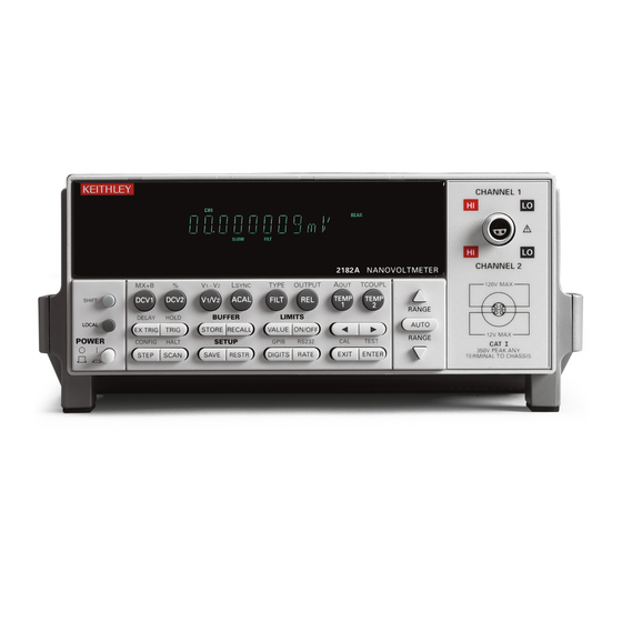
SHIFT key and then the function/operation key. 1 Special keys and power switch SHIFT Use to select a shifted function or operation. LOCAL Cancels GPIB remote mode. POWER Power switch. In position turns 2182 on (1), out position turns it off (0). -
Page 30: Getting Started
Getting Started 2 Function and operation keys Top Row Un-shifted DCV1 Selects Channel 1 voltage measurement function. DCV2 Selects Channel 2 voltage measurement function. V1/V2 Selects Ratio (Channel 1 voltage reading / Channel 2 voltage reading). ACAL Selects automatic gain calibration. FILT Enables/disables filter for selected measurement function. -
Page 31: Getting Started
Getting Started Bottom Row Un-shifted STEP Steps through channels; sends a trigger after each channel. SCAN Scans through channels; sends a trigger after last channel. SAVE Saves present configuration for power-on user default. RESTR Restores factory or user default configuration. DIGITS Changes number of digits of reading resolution. - Page 32 1-10 Getting Started 4 Display annunciators * (asterisk) Readings being stored in buffer. ↔ (more) Indicates additional selections are available. (speaker) Beeper on for limit testing. AUTO Autorange enabled. BUFFER Recalling readings stored in buffer. Channel 1 input displayed. Channel 2 input displayed. CH1 and CH2 Ratio (V1/V2) reading displayed.
-
Page 33: Rear Panel Summary
Getting Started 1-11 Rear panel summary The rear panel of the Model 2182 is shown in Figure 1-2. This figure includes important abbreviated information that should be reviewed before operating the instrument. Figure 1-2 Model 2182 rear panel WARNING: WARNING: NO INTERNAL OPERATOR SERVICABLE PARTS,SERVICE BY QUALIFIED PERSONNEL ONLY. - Page 34 1-12 Getting Started 1 ANALOG OUTPUT Provides a scaled non-inverting DC voltage. With analog output gain set to one, a full range input will result in a 1V analog output. 2 TRIGGER LINK Eight-pin micro-DIN connector for sending and receiving trigger pulses among connected instruments.
-
Page 35: Cleaning Input Connectors
Apply one drop of DeoxIT to each of the four contacts of the LEMO input connector on the Model 2182. You can use a clean wire (such as a resistor lead) to carry a drop of the solution from the bottle of DeoxIT to the connector. -
Page 36: Power-Up
1-14 Getting Started Power-Up Line power connection Perform the following procedure to connect the Model 2182 to line power and turn on the instrument. Check to be sure the line voltage setting on the power module (see Figure 1-3) is correct for the operating voltage in your area. -
Page 37: Setting Line Voltage And Replacing Fuse
FU-91 Power-up sequence On power-up, the Model 2182 performs self-tests on its EPROM and RAM, and momentarily lights all digit segments and annunciators. If a failure is detected, the instrument momentarily displays an error message and the ERR annunciator turns on. Error messages are listed in... -
Page 38: Line Frequency
50Hz (or 400Hz), while 60 indicates that it is set for 60Hz. Display The display of the Model 2182 is primarily used to display readings, along with the units and type of measurement. Annunciators are located at the top, bottom, left, and right of the reading or display message. -
Page 39: Table 1-2 Factory Defaults
Getting Started 1-17 To restore factory or user settings: Press RESTR. Use the keys to display FACT (factory) or USER defaults. Press ENTER. NOTE The basic measurement procedure in the next section (Section 2) assumes factory defaults (Table 1-2). Reset the instrument to the factory default settings when following that step-by-step procedure. - Page 40 1-18 Getting Started Table 1-2 Factory defaults (cont.) Setting Factory Default Scanning Type Internal Timer Channel 1 count Reading count TEMP1 and TEMP2 Digits Filter Analog filter Digital filter Count Mode Moving average Window 0.01% Rate 5 PLC (Slow) Reference junction Internal Relative (REL) Sensor...
-
Page 41: Voltage And Temperature Measurements
Voltage and Temperature Measurements Voltage and Temperature Measurements... - Page 42 Includes the SCPI commands for remote operation. • Low-level considerations — Explains two external factors that can corrupt low-level measurements; thermal EMFs and noise. • Applications — Provides some typical applications for the Model 2182. These include Testing Switch Contacts.
-
Page 43: Measurement Overview
Channel 1 and TEMP2 is available for Channel 2. Depending on which thermocouple type is used (J, K, T, E, R, S, B, or N), the Model 2182 can measure temperature from -200˚C to 1820˚C. The specifications... - Page 44 The thermocouple wires are connected to the copper lugs of the supplied input cable. The connection points are then immersed in the ice bath. The temperature of the ice bath must be entered into the Model 2182 as the simulated reference temperature.
-
Page 45: Performance Considerations
Performance considerations The following aspects of operation affect accuracy and speed. Warm-up After the Model 2182 is turned on, it must be allowed to warm up for at least 2 ⁄ hours to allow the internal temperature to stabilize. After the warm-up period, an ACAL must be performed if the present internal temperature and TCAL differ by more than 1°C. -
Page 46: Autozeroing Modes
This process is known as autozeroing. Internally, the Model 2182 has two amplifiers that have an impact on speed, noise, drift, and offset. These performance aspects can be controlled to some degree by controlling the available autozeroing modes. - Page 47 With Front Autozero for the front-end amplifier enabled (which is the default setting), the Model 2182 performs two A/D measurement cycles for each reading. The first one is a normal measurement cycle, and the second one is performed with the polarity of the amplifier reversed.
-
Page 48: Lsync (Line Cycle Synchronization)
Voltage and Temperature Measurements Controlling autozeroing modes For front panel operation, the two autozeroing modes are controlled from the SHIFT > CONFIG menu as follows: NOTE For remote programming, the commands to control the two autozeroing modes are listed in Table 2-2. -
Page 49: Pumpout Current (Low Charge Injection Mode)
Voltage and Temperature Measurements Perform the following steps to enable or disable line cycle synchronization: Press SHIFT and then LSYNC to display the present state of line synchronization (OFF or ON). key to display “ON” or “OFF.” Press ENTER. The instrument returns to the normal display state. NOTE Line cycle synchronization is not available for integration rates <1 PLC, regardless of the LSYNC setting. -
Page 50: Scpi Programming - Acal, Front Autozero, Autozero, Lsync, And Low Charge Injection
Enable or disable Low Charge Injection Mode for Channel 2 (see “Pumpout current (low charge injection mode)” for details). Note: After sending :DONE, the 2182 goes into the idle state. An INITiate command is needed to trigger readings (see Program Example 1). - Page 51 NOTE: After sending the following commands, the :DONE and :INIT commands will not execute until calibration is completed. CALL SEND(7,”:cal:unpr:acal:init”,status%) ‘ Prepares 2182 for ACAL. CALL SEND(7,”:cal:unpr:acal:step2”,status%) ’ Performs low-level ACAL. CALL SEND(7,”:cal:unpr:acal:done”,status%) ‘ Exits ACAL mode. CALL SEND(7, “:init:cont on”, status%) ‘...
-
Page 52: Connections
The Model 2107 Input Cable, which is a supplied accessory, is terminated with a LEMO con- nector on one end and copper lugs on the other end. The cable is shielded to chassis ground when connected to the Model 2182. The cable wires are made from twisted silver wire. The input cable is shown in Figure 2-2. -
Page 53: Figure 2-2 Model 2107 Input Cable
Temperature measurements using the internal reference junction require that the thermocouple wires be soldered directly to a LEMO connector that mates to the input of the Model 2182. Silver solder should be used to minimize thermal EMFs. Figure 2-3 shows terminal identification for a LEMO connector. -
Page 54: Voltage Only Connections
2182 Test Circuit A. Channel 1 Measurements B. Channel 2 Measurements Dual Channel Measurement Connections — The dual channel feature of the Model 2182 allows you to make comparison measurements within a test circuit. Figure 2-5A shows typical connections to make comparison measurements of two devices in a test circuit. For this measurement configuration, there is no voltage differential between the two measurement... -
Page 55: Temperature Only Connections
A. Typical Measurement Configuration B. Voltage Differential Between Channels Temperature only connections Channel 1 of the Model 2182 can be used to make temperature measurements. Figure 2-6 shows connections using the internal reference junction. Keep in mind that the thermocouple wires must be soldered directly to a LEMO connector as previously explained. -
Page 56: Voltage And Temperature Connections
Test Circuit green CH 2 Ice Bath white 2182 Cable-to-thermocouple wire connection (one of two) Voltage and temperature connections Channel 1 should be used for voltage measurements since it supports a wider range of measurements, leaving Channel 2 to measure temperature. -
Page 57: Cleaning Test Circuit Connectors
Make sure that the copper contact surfaces are free of oxidation before making the connection. DeoxIT can be used to clean copper connectors. A small bottle of DeoxIT is supplied with the Model 2182. The Model 2107 Input Cable is terminated with copper lugs, and the connection terminals of a LEMO connector are copper. - Page 58 2-18 Voltage and Temperature Measurements Temperature configuration If you are going to perform temperature measurements, you have to configure the Model 2182 appropriately from the temperature configuration menu: Temperature configuration menu The items of the temperature configuration menu are explained as follows: •...
-
Page 59: Measuring Voltage And Temperature
Whenever the LEMO connector of the Model 2107 Input Cable (or customized cable) is disconnected from the input of the Model 2182 for a long period of time, the input connectors will have to be cleaned to remove oxidation (see “Cleaning input... -
Page 60: Scpi Programming - Voltage And Temperature Measurements
If not using AUTO range, select the lowest possible measurement range to display the voltage offset. On the Model 2182, press the REL key to zero the display. If applicable, repeat steps 2 through 4 for the other channel. Connect the source. Subsequent readings will not include the thermal EMFs that were nulled out. - Page 61 ‘Select DCV1. CALL SEND(7,“:sens:data:fres?”,status%) ‘Request a fresh ‘reading. reading$ = SPACE$(80) CALL ENTER(reading$, length%, 7, status%) ‘Address 2182 to talk. PRINT reading$ ‘Display reading on CRT. ‘ Measure temperature on Channel 2: CALL SEND(7,“:sens:chan 2”,status%) ‘Select Channel 2. CALL SEND(7,“:sens:func ‘temp’”,status%) ‘Select TEMP2.
-
Page 62: Low-Level Considerations
Effects not noticeable when working with higher voltages are significant in nanovolt signals. The Model 2182 reads only the signal received at its input; therefore, it is important that this signal be properly transmitted from the source. Two principal factors that can corrupt measurements are thermal EMFs and noise induced by AC interference. -
Page 63: Applications
Applications Low-resistance measurements The Model 2182 can be used with a current source to measure resistances at levels well below the capabilities of most conventional instruments. The following paragraphs discuss low- resistance measurement techniques and include some applications to test switches. -
Page 64: Figure 2-11 Measuring Switch Contact Resistance
2-10) to the measured voltage. The Relative feature of the Model 2182 can be used to null out the offset voltage. In general, this is done by disconnecting the current source and zeroing the reading on the Model 2182 by pressing the REL key (see “Measuring voltage and... -
Page 65: Figure 2-12 Measuring Switch Contact Resistance And Temperature
TEMP2 2182 The Model 2182 measures both the voltage across the switch contact and the temperature. These measurements allow you to develop a resistance vs. temperature profile. With current known and voltage measured, resistance can be calculated using Ohms Law: R = V/I. -
Page 66: Figure 2-13 Standard Cell Comparison Measurements
LO inputs of the nanovoltmeter, as shown in Figure 2-13A. The Model 2107 Input Cable (supplied with the Model 2182) should be used to connect the cells to the nanovoltmeter in order to minimize errors caused by thermal EMFs (V Figure 2-13... -
Page 67: Heated Zener Reference And Josephson Junction Array Comparisons
Channel 1 of the Model 2182 measures 0V ±10µV. The null condition indicates that the Heated Zener Reference voltage is the same as the JJ Array voltage. Channel 2 of the Model 2182 is used to determine the exact step that the JJ Array is on. Channel 1 can then be monitored to study noise and drift characteristics of the Heated Zener Reference. - Page 68 2-28 Voltage and Temperature Measurements...
-
Page 69: Range, Digits, Rate, And Filter
Range, Digits, Rate, and Filter Range, Digits, Rate, and Filter... - Page 70 Range, Digits, Rate, and Filter • Range — Provides details on measurement range selection for DCV1 and DCV2. Includes the SCPI commands for remote operation. • Digits — Provides details on selecting display resolution for voltage and temperature measurements. Includes the SCPI commands for remote operation. •...
-
Page 71: Range
Range, Digits, Rate, and Filter Range The selected range affects both accuracy of the voltage measurement as well as the maximum voltage that can be measured. The DCV1 function has five measurement ranges; 10mV, 100mV, 1V, 10V, and 100V. The DCV2 function has three measurement ranges; 100mV, 1V, and 10V. The range setting (fixed or AUTO) is remembered by each voltage function. -
Page 72: Table 3-1 Spci Commands - Range
Range, Digits, Rate, and Filter Autoranging To enable autoranging, press the AUTO key. The AUTO annunciator turns on when autoranging is selected. While autoranging is enabled, the instrument automatically selects the best range to measure the applied signal. Autoranging should not be used when optimum speed is required. -
Page 73: Table 3-2 Spci Commands - Digits
Range, Digits, Rate, and Filter Digits The DIGITS key sets display resolution for the Model 2182. Display resolution for voltage readings can be set from 3 ⁄ to 7 ⁄ digits. For temperature readings, resolution can be set from 4 to 7 digits. -
Page 74: Figure
3-1. The Model 2182 is optimized for the 1 PLC to 5 PLC reading rate. At these speeds (Lowest noise region in the graph), the Model 2182 will make corrections for its own internal drift and still be fast enough to settle a step response <100ms. -
Page 75: Table 3-3 Scpi Commands - Rate
Range, Digits, Rate, and Filter NOTE For remote operation, the integration time can be set from 0.01 PLC to 60 PLC (50 PLC for 50Hz line power). Integration time can instead be set as an aperture time from 166.67µsec (200µsec for 50Hz) to 1 second. Perform the following steps to set the integration rate: Select the desired function. -
Page 76: Filter
20dB/decade starting at 18Hz. A primary use of the Analog Filter is to keep the high-gain input stage of the Model 2182 from saturating due to the presence of high AC and DC voltage. Note, however, that the filter only attenuates AC voltages for the 10mV range of the Model 2182. - Page 77 Range, Digits, Rate, and Filter Filter window — The digital filter uses a window to control filter threshold. As long as the input signal remains within the selected window, A/D conversions continue to be placed in the stack. If the signal changes to a value outside the window, the filter resets, and the filter starts processing again starting with a new initial conversion value from the A/D converter.
-
Page 78: Figure 3-2 Moving And Repeating Filters
3-10 Range, Digits, Rate, and Filter Figure 3-2 Moving and repeating filters Conversion #11 Conversion #12 Conversion #10 Reading Reading Reading Conversion Conversion #3 Conversion #1 A. Type - Moving Average, Readings = 10 Conversion #10 Conversion #20 Conversion #30 Reading Reading Reading... - Page 79 Range, Digits, Rate, and Filter 3-11 Filter control and configuration The FILT key toggles the state of the Filter. When the Filter is enabled, the FILT annunciator is on. When disabled, the FILT annunciator is off. The analog and digital filters can be configured while the Filter is enabled or disabled.
-
Page 80: Relative
3-12 Range, Digits, Rate, and Filter SCPI programming - filter NOTE All the filter commands are part of the SENSe Subsystem. Table 3-4 SCPI commands - filter Commands Description Default For DCV1: :SENSe: SENSe Subsystem: :VOLTage Volts function: [:CHANnel1] Channel 1 (DCV1): :LPASs <b>... -
Page 81: Digital Filter
Range, Digits, Rate, and Filter 3-13 Programming example The following program fragment configures the Filter for Channel 2 voltage (DCV2). It disables the analog filter and enables the digital filter (5% window, count 10, moving). ‘Analog Filter: CALL SEND(7,“:sens:volt:chan2:lpas off”,status%) ‘Disable analog filter. - Page 82 3-14 Range, Digits, Rate, and Filter...
-
Page 83: Mx+B And Percent (%)
Relative, mX+b, and Percent Relative, mX+b, and Percent (%) -
Page 84: Percent (%)
Relative, mX+b, and Percent (%) • Relative — Explains how to null an offset or establish a baseline value. Includes the SCPI commands for remote operation. • mX+b and Percent (%) — Covers these two basic math operations, and includes the SCPI commands for remote operation. - Page 85 Relative with Ratio and Delta. For offsets that vary, the DC current-reversal technique should be used instead of REL. This technique uses the Delta measurement mode of the Model 2182 to cancel offsets. See “Delta” Section 5 for details.
-
Page 86: Scpi Programming - Relative
Relative, mX+b, and Percent (%) SCPI programming - relative Table 4-1 SCPI commands - relative Commands Description Default For DCVI and DCV2: :SENSe SENSe Subsystem: :VOLTage Volts function: [:CHANnel1] Channel 1 (DCV1): :REFerence <n> Specify rel value: –120 to 120 (volts). :STATe <b>... - Page 87 Relative, mX+b, and Percent (%) Programming examples - relative Program Example 1 — This program fragment shows how to null out zero offset for the DCV1 function. Be sure to short the Channel 1 input. CALL SEND(7,“:syst:pres”,status%) ‘Selects DCV1 and enables ‘autorange.
- Page 88 Relative, mX+b, and Percent (%) mX+b and percent (%) mX+b This math operation manipulates normal display readings (X) mathematically according to the following calculation: Y = mX+b where: X is the normal display reading m and b are user-entered constants for scale factor and offset Y is the displayed result To configure and control the mX+b calculation, perform the following steps: Press SHIFT and then MX+B to display the present scale factor:...
- Page 89 Relative, mX+b, and Percent (%) Percent (%) This math function determines percent deviation from a specified reference value. The percent calculation is performed as follows: Input – Reference Percent = ––––––––––––––––– × 100% Reference where: Input is the normal display reading Reference is the user entered constant Percent is the displayed result To configure and control the percent calculation, perform the following steps:...
-
Page 90: Scpi Programming - Mx+B And Percent
Relative, mX+b, and Percent (%) SCPI programming - mX+b and percent Table 4-2 SCPI commands - mX+b and percent Commands Description Default :CALCulate :FORMat <name> Select calculation; NONE, MXB or PERCent. NONE :KMATh Path to configure mX+b and Percent: :MMFactor <NRf> Specify scale factor (M) for mX+b: –100e6 to 100e6. -
Page 91: Ratio And Delta
Ratio and Delta Ratio and Delta... -
Page 92: Ratio
Delta — Explains how to perform Delta measurements, which are used to cancel the effects of thermal EMFs in the test leads. Features the use of a Keithley SourceMeter with the Model 2182 to perform Delta measurements. Includes the effects of Filter on Delta measurements. - Page 93 Ratio and Delta Step 1 Connect voltages to be measured to the Model 2182. Details on connecting the Model 2182 to the voltages to be measured are provided in Section 2 (see “Connections”). WARNING A hazardous voltage condition exists at or above 42V peak. To prevent electric shock that could result in injury or death, NEVER make or break connections while hazardous voltage is present.
-
Page 94: Filter, Rel, And Ranging Considerations
Ratio and Delta Filter, Rel, and Ranging considerations Filter considerations As explained in Section 3, a unique Filter configuration can be established for each voltage channel. However, the Filter configuration for Channel 1 is applied to both channels when Ratio is enabled. - Page 95 Ratio and Delta NOTE The previous calculation shows Filter enabled. If Filter is not used, remove the “Filt” component from the calculation. When Ratio is enabled, the state (on or off) of the REL annunciator depends on which measurement function was last selected. If on DCV1 when Ratio is enabled, the state of the REL annunciator (on or off) will indicate the state (enabled or disabled) of Rel for DCV1.
-
Page 96: Delta
Rel V1 is the Rel value established for DCV1. The “REL” annunciator will be on when Rel is enabled. The Model 2182 is optimized to provide low-noise readings when measurement speed is set from 1 to 5 PLC. At 1 PLC, current can be reversed after 100msec. At 5 PLC, current can be reversed after 333msec. -
Page 97: Figure
Figure 5-1B shows what happens when the current is reversed. The measurement by the Model 2182 still includes the 10µV of thermal EMF, but the voltage across the DUT is now negative. Therefore, the Model 2182 will measure 90µV: 2182 THERM = 10µV - 100µV... -
Page 98: Figure
Figure 5-2. The current source will alternate between +1mA and –1mA. When using Delta, the Model 2182 performs the first voltage measurement (V1t1) while sourcing +1mA. The second voltage measurement (V1t2) is performed while sourcing –1mA: NOTE When using the Model 2182 to perform Delta measurements, RATE must be set to 1 PLC or 5 PLC to optimize measurement performance. -
Page 99: Selecting Delta
• Delta cannot be selected if stepping or scanning. • Reading HOLD cannot be used with Delta. Delta measurements by the Model 2182 require the use of an alternating polarity source. The source must have external triggering capabilities that are compatible with the external triggering capabilities of the Model 2182. - Page 100 (Model 8501) from the Model 2182 to the SourceMeter. NOTE This procedure assumes that the Model 2182 is using the factory default Trigger Link line configuration; Line 1 is VMC (output), Line 2 is EXT TRIG (input).
-
Page 101: Figure
Ratio and Delta 5-11 Figure 5-3 Delta measurement connections 8501 Trigger Link Cable 2182 SourceMeter CH 1 0.1Ω Step 3 Configure the trigger model of the SourceMeter. The menu structure to configure triggers is accessed by pressing CONFIG and then TRIG. - Page 102 C. Press EX TRIG to place the instrument in the external trigger mode. This will halt measurements. D. If a longer settling time is required before performing each measurement, set a manual delay from the Model 2182. Press SHIFT and then DELAY to select and set delay. NOTE Do not set a delay on the SourceMeter, as this may adversely affect trigger synchronization between the SourceMeter and the Model 2182.
- Page 103 Step 9 Set up the Model 2182 to store readings in the buffer (optional). On the Model 2182, press STORE and set the number of Delta readings to store in the buffer. Press ENTER to enable the buffer. Step 10 Start the sweep from the SourceMeter.
-
Page 104: Figure
A/D conversion for the V1t1 phase of the Delta measurement, and then triggers the SourceMeter to output the second point of the sweep (-1mA). At this point, the Model 2182 does not wait for the return trigger from the SourceMeter to perform the V1t2 phase of the Delta measurement. -
Page 105: Filter Considerations
On each V1t2 A/D conversion, the Delta calculation is performed using the filtered V1t1 and V1t2 values and the result is displayed on the Model 2182. For every subsequent Delta measurement, the operation is basically the same except that each stack only requires one reading to fill it. -
Page 106: Scpi Programming - Ratio And Delta
‘ range control. CALL SEND (7, “:sens:volt:ratio”, status%) ‘ Enable Ratio. CALL SEND (7, “:sens:data:fresh?”, status%) ‘ Request a fresh reading. reading$ = SPACE$(80) CALL ENTER(reading$, length%, 7, status%) ‘ Address 2182 to talk. PRINT reading$ ‘ Display Ratio reading on CRT. - Page 107 Autozero is disabled to double the speed of Delta. Three Delta measurements will be performed; one at a source value of 10µA, one at 20µA, and one at 50µA. The three readings will be stored in the buffer of the Model 2182. CALL SEND (7, “:syst:pres”, status%) ‘...
-
Page 108: Figure
(1kΩ × 1mA = 1V) or autorange. Channel 2, which is used to measure the 10kΩ resistance component, should be set to the 10V range (or autorange). When Ratio is enabled, the Model 2182 will display the result of V1 (≈1V) divided by V2 (≈10V): Filt V1 ≈1V... -
Page 109: Testing Superconductor Materials
Ratio and Delta 5-19 For even greater precision, the Relative feature of the Model 2182 can be used to null out thermal EMFs, which can corrupt low voltage measurements. Use Rel as follows: While displaying the Ratio result, disconnect the current source from the network. -
Page 110: Figure
Keithley SourceMeter (Model 2400, 2410, or 2420) is used to source current through the DUT and the Model 2182 measures the voltage across the DUT. Keep in mind that the I-Source of the SourceMeter is a constant current source. Therefore, the current through the DUT will remain constant as the resistance of the DUT increases. -
Page 111: Figure 5-7 H-V Curve (Fixed I)
fixed current of 1mA, the custom sweep can be configured to alternate between +1mA and -1mA (see Figure 5-8). By enabling Delta measurements on the Model 2182, the effects of thermal EMFs in the test leads will automatically be canceled during the source-measure process. Figure 5-8 SourceMeter output—2-point custom sweep +1mA –1mA... -
Page 112: Figure 5-9 I-V Curve (Fixed H)
(10µA × 100Ω = 1mV) and stores the reading in its buffer at location 1. At the same time, Model 2182 #2 measures the DUT and stores that reading in its buffer at location 1. At the next sweep point (20µA), Model 2182 #1 measures 2mV and stores the reading in its buffer at location 2, and Model 2182 #2 measures the DUT and stores the reading in its buffer at location 2. -
Page 113: Figure 5-10 Test Circuit-Fixed H (Vary I)
Source ±I <4K Cryostat The readings in the buffer of Model 2182 #1 correspond to the current sweep values. You can then use the buffer location numbers to reference DUT readings to current amplitudes: Model 2182 #1 Buffer Model 2182 #2 Buffer RDG NO. - Page 114 Therefore, the custom sweep in Figure 5-11 would be made up of 30 points (P0 through P29). The procedure to use the SourceMeter and Model 2182 to perform Delta measurements is provided in “Delta measurement procedure using a SourceMeter.” That procedure (presented earlier in this section under “Delta”) uses a 2-point custom sweep and will have to be modified...
-
Page 115: Figure 5-11 Sourcemeter Output-30-Point Custom Sweep
Ratio and Delta 5-25 Figure 5-11 SourceMeter output—30-point custom sweep +50µA +20µA +10µA –10µA –20µA –50µA... -
Page 116: Figure 5-12 Trigger Link Connections Using Two Model 2182S
(VMC) required from the Model 2182s is provided by unit #1. VMC from unit #2 must not be used. Figure 5-12 Trigger link connections using two Model 2182s SourceMeter 2182 #1 2182 #2 Rear Panel Rear Panel Rear Panel... -
Page 117: Buffer
Buffer Buffer... -
Page 118: Buffer Operations
SCPI programming — Covers the SCPI commands used to control buffer operations. Buffer operations The Model 2182 has a buffer to store from two to 1024 readings and units. It also stores the channel number for step/scan readings and overflow readings. In addition, recalled data includes statistical information (minimum, maximum, peak-to-peak, average, and standard deviation). -
Page 119: Figure 6-1 Buffer Locations
Buffer Recall Perform the following steps to view stored readings and buffer statistics: Press RECALL. The BUFFER annunciator turns on to indicate that stored readings are being displayed. The arrow annunciator (↔) also turns on to indicate that additional data is available for viewing. -
Page 120: Buffer Statistics
∑ – -- - ------------------------------------------------------------- - where: X i is a stored reading. n is the number of stored readings. NOTE The Model 2182 uses IEEE-754 floating point format for math calculations. -
Page 121: Scpi Programming - Buffer
Buffer SCPI programming - buffer Buffer commands are summarized in Table 6-1. TRACe subsystem commands are used to store and recall readings in the buffer, and CALCulate2 commands are used to obtain statistics from the buffer data. Additional information on these commands is provided after the table. Table 6-1 SCPI commands - buffer Commands... -
Page 122: Programming Example
‘Start storing readings. CALL SEND(7,“:trac:data?”,status%) ‘Request all stored ‘readings. reading$ = SPACE$(80) CALL ENTER(reading$, length%, 7, status%) ‘Address 2182 to talk. PRINT reading$ ‘Display all buffer ‘readings on CRT. ‘ Calculate Mean of Buffer Readings: CALL SEND(7,“:calc2:form mean”,status%) ‘Select mean calculation. -
Page 123: Triggering
Triggering Triggering... - Page 124 Reading hold — Explains the Reading Hold feature which is used to screen out readings that are not within a specified reading window. • External triggering — Explains external triggering which allows the Model 2182 to trigger other instruments, and be triggered by other instruments. •...
-
Page 125: Figure
From the front panel, the unit is considered idle at the end of a step or scan operation when the reading for the last channel remains displayed. To restore triggers, press SHIFT and then HALT. Once the Model 2182 is taken out of idle, operation proceeds through the trigger model. -
Page 126: Table 7-1 Auto Delay Times
A programmable delay is available after event detection. It can be set manually or an auto delay can be used. With auto delay, the Model 2182 selects a delay based on the selected voltage range. The auto delays are listed in Table 7-1. -
Page 127: Figure
Triggering Device action The primary device action is a measurement. However, the device action block could include the following additional actions (refer to Figure 7-2): Figure 7-2 Device action From Delay block To Output Trigger of Figure 7-1 block of Figure 7-1 Hold Chan Filter... -
Page 128: Reading Hold (Autosettle)
Press DCV1 to measure voltage on Channel 1. Apply the test signal to Channel 1 of the Model 2182. Once the signal becomes stable enough to satisfy the hold condition, the reading is released and the beeper sounds (if enabled). -
Page 129: Figure 7-3 Rear Panel Pinout
Pressing the EX TRIG key again toggles back to continuous triggers. The Model 2182 uses two lines of the Trigger Link rear panel connector as External Trigger (EXT TRIG) input and Voltmeter Complete (VMC) output. The EXT TRIG line allows the Model 2182 to be triggered by other instruments. -
Page 130: Trigger Link Input Pulse Specifications (Ext Trig)
Figure 7-4. In general, external triggers can be used to control measure operations. For the Model 2182 to respond to external triggers, the trigger model must be configured for it. Figure 7-4 Trigger link input pulse specifications (EXT TRIG) -
Page 131: Dut Test System
7-7. Trigger Link of the Model 2182 is connected to Trigger Link (either IN or OUT) of the Model 7001/7002. Note that with the default trigger settings on the Model 7001/7002, line #1 is an input and line #2 is an output. -
Page 132: Operation Model For Triggering Example
Number of scans = 1 Channel spacing = TrigLink To run the test and store readings in the Model 2182 with the unit set for external triggers, press STEP or SCAN. The Model 2182 waits (with the asterisk annunciator lit) for an external trigger from the Model 7001/7002. - Page 133 Triggering 7-11 A. Pressing EX TRIG then STEP or SCAN on the Model 2182 places it at point A in the flowchart, where it is waiting for an external trigger. B. Pressing STEP on the Model 7001/7002 takes it out of the idle state and places operation at point B in the flowchart.
-
Page 134: Figure
Keithley Model 220 Current Source can be connected to the Trigger Link of the Model 2182 using the adapter cable. When used with the STEP mode of the Model 220, you can perform synchronized source-measure operations without the use of a computer. -
Page 135: Trigger Model (Remote Operation)
Triggering 7-13 SCPI programming - triggering Trigger model (remote operation) The following paragraphs describe how the Model 2182 operates for remote operation. The flowchart in Figure 7-10 summarizes operation over the bus. The flowchart is called the trigger model because operation is controlled by SCPI commands from the Trigger subsystem. Key SCPI commands are included in the trigger model. - Page 136 7-14 Triggering Idle and initiate The instrument is considered to be in the idle state whenever operation is at the top of the trigger model. As shown in Figure 7-10, initiation needs to be satisfied to take the instrument out of idle.
-
Page 137: Trigger Model Operation
five readings in the buffer. Output trigger — The Model 2182 will send one or more output triggers. The output trigger is applied to the Trigger Link connector on the rear panel. It can be used to trigger an external instrument to perform an operation. -
Page 138: Triggering Commands
Beeper control: :STATe <b> Enable or disable the beeper. *RST Restore *RST defaults (see “Default” column of this table). Places 2182 in the idle state. Notes: 1. Defaults for continuous initiation: SYSTem:PRESet enables continuous initiation. *RST disables continuous initiation. 2. Defaults for trigger count: SYSTem:PRESet sets the count to INF (infinite). -
Page 139: Programming Example
7-17 Reference: ABORt — With continuous initiation disabled, the 2182 goes into the idle state. With continuous initiation enabled, operation continues at the top of the trigger model. INITiate — Whenever the instrument is operating within the trigger model, sending this command causes an error and will be ignored. - Page 140 7-18 Triggering...
- Page 141 Limits Limits...
-
Page 142: Limits
Limits • Limit operations — Explains Limit 1 and Limit 2 testing operations. • SCPI programming — Covers the SCPI commands for remote operation. • Application — Provides an application that sorts resistors by tolerances. -
Page 143: Figure 8-1 Default Limits
Limits Limit operations Limit operations set and control the values that determine the HI/IN/LO status of subsequent measurements. The limit test is performed on the result of an enabled Rel, mX+b, or Percent operation. There are two sets of limits. Limit 1 uses high and low limits (HI1 and LO1) as does Limit 2 (HI2 and LO2). -
Page 144: Setting Limit Values
Limits Setting limit values Use the following steps to enter high and low limit values: Press the Limits VALUE key to view the present HI1 limit value: HI1:+1.000000 ^ (default) To change the HI1 limit, use the cursor keys ( ) and the manual range keys ( and ) to display the desired value. -
Page 145: Scpi Programming - Limits
Limits SCPI programming - limits For remote operation, the testing capabilities of Limit 1 and Limit 2 are the same. Limit 1 and/or Limit 2 can be enabled. The commands to configure and control limit testing are listed in Table 8-1. - Page 146 Programming example The following program fragment performs limit tests on a voltage input to Channel 1: ‘Configure 2182 for one-shot DCV1 measurements: CALL SEND(7, “*rst”,status%) ‘Put 2182 in a one-shot mode. ‘ Configure limit tests: CALL SEND(7,“:calc3:lim:upp 0.1”,status%)
-
Page 147: Setup To Test 10Ω Resistors
Limits can be used to sort resistors. Figure 8-2 shows a basic setup to test 10Ω resistors. The Model 220 is used to source a constant 1mA through the resistor and the Model 2182 measures the voltage drop. Figure 8-2 Setup to test 10 Ω... -
Page 148: Figure
Nulling thermal EMFs — To maximize handling speed, quick-disconnect test clips are typically used for the resistor connections. Unfortunately, these connections may contribute enough thermal EMFs to corrupt the measurement. The Relative feature of the Model 2182 can be used to null out this offset as follows:... -
Page 149: Stepping And Scanning
Stepping and Scanning Stepping and Scanning... - Page 150 Stepping and Scanning • Step/Scan overview — Summarizes the stepping and scanning operations. • Front panel trigger models — Uses the trigger model to illustrate how stepping and scanning operates. • Stepping/Scanning controls — Covers the front panel keys used to configure and control stepping/scanning.
-
Page 151: Step/Scan Overview
Stepping and Scanning Step/Scan overview The Model 2182 can step or scan its two input channels or be used with external scanner cards installed in switching mainframes such as Models 707, 7001, and 7002. The following paragraphs summarize the various aspects of stepping/scanning using the Model 2182. -
Page 152: Front Panel Trigger Models
• Device action — Measurements are performed at this block. The first measurement is performed on Channel 2 of the Model 2182. Subsequent measurements are performed on Channel 1. Note that every reading is automatically stored in the buffer. •... -
Page 153: Figure
Stepping and Scanning Figure 9-1 Front panel triggering (internal scanning) Idle Another Trigger Counter Scan? Event Control Detection Source Output Trigger Immediate External Timer Another Sample Reading Counter Delay Device Action Figure 9-2 Front panel triggering (other step/scan operations) Idle Another Trigger Reading... -
Page 154: Other Stepping/Scanning Operations
• Device action — Measurements are performed at this block. For internal stepping, the first measurement is performed on Channel 2 of the Model 2182. Subsequent measurements are performed on Channel 1. For internal scanning and external scanning, each measurement corresponds to a channel in the step/scan list. All readings are automatically stored in the buffer. - Page 155 Stepping and Scanning Step/Scan configuration Internal Stepping/Scanning The settings for internal stepping and scanning are explained as follows: Timer — The maximum timer interval is 99H:99M:99.999S (Hour:Minute:Second format). Channel 1 Count — This specifies the number of measurements to be performed while on Channel 1.
-
Page 156: Stepping/Scanning Examples
Stepping and Scanning External Stepping/Scanning The settings for external stepping/scanning are explained as follows: Min/Max Values — These two values specify the beginning and ending channels for the step/scan list. Valid values for Min is 1 to 799, and valid values for Max is 2 to 800. However, the Max value must be larger than the Min value. -
Page 157: Internal Stepping
Stepping and Scanning Operation: When the SCAN key is pressed, operation proceeds to Device Action where a measurement on Channel 2 is performed. The sample counter is decremented to 4 causing operation to loop back to Device Action for a measurement on Channel 1. Operation loops back to Device Action three more times to complete the scan cycle. -
Page 158: External Scanning
Figure 7-8 shows trigger model operation for the test. Both instrument setups assume factory defaults. Note that Channel 1 of the Model 2182 must be used for external scanning. On the Model 7001 Switch System, enter a scan list of channels 1 to 8 on card 1. -
Page 159: Figure 9-3 External Scanning Example With Model 7001
Stepping and Scanning 9-11 Figure 9-3 External scanning example with Model 7001 Model 7001 Model 2182 (from “reset setup”) (from “factory setup”) SCAN CHANNELS 1!1-1!8 CONFIGURE SCAN CHAN-CONTROL CHANNEL-SPACING TRIGLINK ASYNCHRONOUS CHAN-COUNT SCAN-CONTROL SCAN-COUNT SHIFT-CONFIG TYPE:EXT MIN CHAN: 001 MAX CHAN: 008... -
Page 160: Scpi Programming - Stepping And Scanning
9-12 Stepping and Scanning SCPI programming - stepping and scanning Commands to scan are listed in Table 9-1. Notice that many commands from the TRIGger Subsystem are used for scanning. See Section 7 for details on triggering. Table 9-1 SCPI commands - stepping and scanning Commands Description Default... -
Page 161: Programming Example
CALL SEND(7,“:rout:scan:int:cco 4”,status%) 'Set channel 1 count to 4. CALL SEND(7,“:rout:scan:lsel int”,status%) 'Enable internal scan. CALL SEND(7,“:read?”,status%) 'Trigger scan and request 'readings. reading$ = SPACE$ (80) CALL ENTER (reading$,length%,7,status%) 'Address 2182 to talk. PRINT reading$ 'Display the 5 readings on 'the CRT. -
Page 162: Figure 9-4 Waveform To Be Programmed Into Model 2400
9-4. This sweep will store into the 2182 memory and can be recalled at the end of the sweep. By having the 2400 and 2182 in a tight hardware control, the DC current-reversal technique can be run at a rate of 8/sec. at a 1PLC integration time. This will greatly reduce any thermal EMFs in the system by being able to reverse the DC current before any temperature effects can occur. -
Page 163: Setup Of Model 2182 And Model 2400
; Note Ch1 will store 3 readings / 2400 programmed current level. Ch2 will store 1 reading / 2400 programmed current level. Rdg Count 48 Figure 9-5 Setup of Model 2182 and Model 2400 8501 Trigger Link Cable 2400 2182 2107 100Ω... - Page 164 ON the 2400, enable SWEEP (Note: Arm annunciator comes on). Press Trig on 2400. After completion of the sweep, recall the data from the 2182 using the “TRACe” command. To remove thermal EMFs from the readings, do the following math on the recalled data:...
- Page 165 An example program using “QBASIC ” was written that sets up an Array for all the data out of the 2182 buffer, parses the comma separated data into the array, and calculates the DC current reversal data for both Channel 1 and Channel 2.
- Page 166 DIM Readings!(1 TO NumRdgs) 'array of the 48 individual readings in 'numerical representation form - converted from 'ASCII CALL send(Addr, "TRACE:DATA?", status%) 'ask 2182 for the buffer response CALL enter(AsciiRdgsBuf$, length%, Addr, status%) 'read in buffer response ' Start Parsing the data readings...
- Page 167 Stepping and Scanning 9-19 FOR j = 1 TO (CalcReadings) Chan2! = Readings!(k%) - Reading!(k% + NumRdgsPerStep) Chan2! = Chan2! / 2 DataCH2$(j) = STR$(Chan2!) CH1pos! = 0! CH1neg! = 0! FOR i = 1 TO (NumRdgsPerStep - 1) CH1pos! = CH1pos! + Reading!(k% + i) CH1neg! = CH1neg! + Reading!(k% + i + NumRdgsPerStep) NEXT i Chan1! = ((CH1pos! - CH1neg!) / ((NumRdgsPerStep - 1) * 2))
- Page 168 9-20 Stepping and Scanning...
- Page 169 Analog Output Analog Output...
- Page 170 10-2 Analog Output • Overview — Covers the capabilities of the Analog Output. • Operation — Explains how to configure and control the Analog Output. • SCPI programming — Covers the SCPI commands associated with the Analog Output.
-
Page 171: Overview
The Analog Output voltage is calculated as follows: Analog Output = (Gain × Rdg/Rng) – Offset where: Gain is the user entered gain factor. Rdg is the reading on the Model 2182. Rng is the measurement range. Offset is the user entered offset value. NOTE... - Page 172 10-4 Analog Output Temperature The analog output voltage for temperature measurements depends on thermocouple type and the selected units (°C, °F, or K). The 1.2V analog output is scaled to the maximum positive temperature reading. For example, the measurement range for the Type J thermocouple is -200°C to +760°C.
-
Page 173: Operation
Analog Output 10-5 Operation Analog output connections The analog output is accessed from the rear panel BNC connector that is labeled “ANALOG OUTPUT.” This connector requires a cable that is terminated with a standard male BNC connector. Output resistance — The output resistance of Analog Output is 1kΩ ±5%. To minimize the effects of loading, the input resistance of the device connected to Analog Output should be as high as possible. -
Page 174: Scpi Programming - Analog Output
10-6 Analog Output SCPI programming - analog output Commands for analog output are summarized in Table 10-2. Additional information on these commands follows the table. The Ref column in the table provides reference for this information. Table 10-2 SCPI commands - analog output Commands Description Default... - Page 175 Remote Operation Remote Operation...
- Page 176 11-2 Remote Operation • Selecting and configuring an interface — Explains how to select and configure an interface: GPIB or RS-232. • GPIB operation and reference — Covers the following GPIB topics: • GPIB Bus Standards • GPIB Bus Connections •...
-
Page 177: Interfaces
GPIB interface — The GPIB is the IEEE-488 interface. The Model 2182 must be assigned to a unique address. At the factory the address is set to 07, but can be set to any value from 0 to 30. - Page 178 11-4 Remote Operation Interface selection and configuration procedures When you select (enable) the GPIB interface, the RS-232 interface disables. Conversely, selecting (enabling) the RS-232 interface disables the GPIB interface. GPIB interface The GPIB interface is selected and configured from the GPIB menu structure. From this menu, you can enable or disable the GPIB interface, and check or change the following settings: •...
-
Page 179: Remote Operation
Remote Operation 11-5 Perform the following steps to select and configure the RS-232 interface: NOTE To retain a present RS-232 setting, press ENTER with the setting displayed. You can exit from the menu structure at any time by pressing EXIT. Press SHIFT and then RS232 to access the RS-232 menu. -
Page 180: Figure 11-1 Ieee-488 Connector
IEEE-488-1987.2 and defines a standard set of commands to control every programmable aspect of an instrument. GPIB bus connections To connect the Model 2182 to the GPIB bus, use a cable equipped with standard IEEE-488 connectors as shown in Figure 11-1. -
Page 181: Ieee-488 Connections
IEEE-488 cables. Available shielded cables from Keithley are Models 7007-1 and 7007-2. To connect the Model 2182 to the IEEE-488 bus, follow these steps: Line up the cable connector with the connector located on the rear panel. The connector is designed so that it will fit only one way. -
Page 182: Primary Address Selection
Programming examples used throughout this manual presume Microsoft QuickBASIC version 4.5 (or higher) and a Keithley KPC-488.2 or Capital Equipment Corporation IEEE interface with CEC driver 2.11 or higher. The Model 2182 must be set to address 07 for the IEEE-488 bus. -
Page 183: General Bus Commands
Model 2182. If the program message includes a query command, then the CALL ENTER command is required to get the response message from the Model 2182. The CALL ENTER command addresses the Model 2182 to talk. The following example program fragment demonstrates how CALL SEND and CALL ENTER commands are used. - Page 184 The General Bus Commands are explained as follows: REN (remote enable) The remote enable command is sent to the Model 2182 by the controller to set up the instrument for remote operation. Generally, the instrument should be placed in the remote mode before you attempt to program it over the bus.
- Page 185 CALL TRANSMIT (“UNL LISTEN 7 SDC”, status%)‘ Clears 2182. GET (group execute trigger) GET is a GPIB trigger that is used as an event to control operation. The Model 2182 reacts to this trigger if it is the programmed control source. The control source is programmed from the SCPI TRIGger subsystem.
-
Page 186: Front Panel Gpib Operation
Remote Operation SPE, SPD (serial polling) Use the serial polling sequence to obtain the Model 2182 serial poll byte. The serial poll byte contains important information about internal functions. Generally, the serial polling sequence is used by the controller to determine which of several instruments has requested service with the SRQ line. -
Page 187: Status Structure
Status structure Figure 11-4 for the Model 2182’s status structure. Instrument events, such as errors, are monitored and manipulated by four status register sets. Notice that these status register sets feed directly into the Status Byte Register. More detailed illustrations of these register sets are... -
Page 188: Figure 11-4 Model 2182 Status Model Structure
11-14 Remote Operation Figure 11-4 Model 2182 status model structure Questionable Event Questionable Questionable Enable Condition Event Register Register Register & & & & Temperature Summary Temp Temp & Temp & & Logical & Calibration Summary & ACAL Summary Acal... - Page 189 Remote Operation 11-15 Condition registers Figure 11-4 shows, some register sets have a condition register. A condition register is a real-time, read-only register that constantly updates to reflect the present operating conditions of the instrument. For example, while a measurement is being performed, bit B4 (Meas) of the Operation Condition Register is set.
-
Page 190: Figure 11-5 Standard Event Status
(B15 - B11) (B10) (B9) (B8) (B7) (B6) (B5) (B4) (B3) (B2) (B1) (B0) (See Figure 11-9). Idle = Idle state of the 2182 & = Logical AND Filt = Filter Settled OR = Logical OR Trig = Trigger Layer... -
Page 191: Figure 11-7 Measurement Event Status
Remote Operation 11-17 Figure 11-7 Measurement event status BHF BAV Measurement (B15 - B10) (B9) (B8) (B7) (B6) (B5) (B4) (B3) (B1) (B0) Condition Register (B2) Measurement Event (B15 - B10) (B9) (B8) (B7) (B6) (B5) (B4) (B3) (B2) (B1) (B0) Register &... - Page 192 Queue is considered cleared when it is empty. An empty Output Queue clears the MAV bit in the Status Byte Register. Read a message from the Output Queue by addressing the Model 2182 to talk after the appropriate query is sent.
-
Page 193: Status Byte And Service Request
Remote Operation 11-19 Status byte and service request (SRQ) Service request is controlled by two 8-bit registers: the Status Byte Register and the Service Request Enable Register. Figure 11-9 shows the structure of these registers. Figure 11-9 Status byte and service request Status Summary Messages Read by Serial Poll Service... - Page 194 Typically, service requests (SRQs) are managed by the serial poll sequence of the Model 2182. If an SRQ does not occur, bit B6 (RQS) of the Status Byte Register will remain cleared, and the program will simply proceed normally after the serial poll is performed.
-
Page 195: Programming Syntax
Remote Operation 11-21 The serial poll automatically resets RQS of the Status Byte Register. This allows subsequent serial polls to monitor bit B6 for an SRQ occurrence generated by other event types. After a serial poll, the same event can cause another SRQ, even if the event register that caused the first SRQ has not been cleared. - Page 196 11-22 Remote Operation • Parameter types – The following are some of the common parameter types: <b> Boolean – Used to enable or disable an instrument operation. 0 or OFF disables the operation, and 1 or ON enables the operation. :OUTPut:RELative ON Enable Analog Output Rel <name>...
- Page 197 Remote Operation 11-23 Query commands The Query command requests the presently programmed status. It is identified by the question mark (?) at the end of the fundamental form of the command. Most commands have a query form. :TRIGger:TIMer?Queries the timer interval Most commands that require a numeric parameter(<n>) can also use the DEFault, MINimum, and MAXimum parameters for the query form.
- Page 198 11-24 Remote Operation Short-form rules Use the following rules to determine the short-form version of any SCPI command: • If the length of the command word is four letters or less, no short form version exists. :auto = :auto These rules apply to command words that exceed four letters: •...
- Page 199 Remote Operation 11-25 Single command messages The above command structure has three levels. The first level is made up of the root command (:STATus) and serves as a path. The second level is made up of another path (:OPERation) and a command (:PRESet).
- Page 200 Sending a response message After sending a query command, the response message is placed in the Output Queue. When the Model 2182 is addressed to talk, the response message is sent from the Output Queue to the computer. Multiple response messages If you send more than one query command in the same program message (see “Multiple...
-
Page 201: Rs-232 Interface Reference
Make sure that the programming terminal that you are connecting to the Model 2182 can support the baud rate you selected. Both the Model 2182 and the other device must be configured for the same baud rate. To select a baud rate, follow these steps:... - Page 202 Flow control (signal handshaking) Signal handshaking between the controller and the instrument allows the two devices to communicate to each other regarding being ready or not ready to receive data. The Model 2182 does not support hardware handshaking (flow control).
-
Page 203: Figure 11-10 Rs-232 Interface Connector
Remote Operation 11-29 RS-232 connections The RS-232 serial port can be connected to the serial port of a controller (i.e., personal computer) using a straight through RS-232 cable terminated with DB-9 connectors. Do not use a null modem cable. The serial port uses the transmit (TXD), receive (RXD), and signal ground (GND) lines of the RS-232 standard. -
Page 204: Table 11-3 Pc Serial Port Pinout
11-30 Remote Operation Table 11-3 PC serial port pinout DB-9 DB-25 Signal Pin Number Pin Number DCD, data carrier detect RXD, receive data TXD, transmit data DTR, data terminal ready GND, signal ground DSR, data set ready RTS, request to send CTS, clear to send RI, ring indicator Error messages... - Page 205 Common Commands Common Commands...
-
Page 206: Common Commands
*RCL <NRf> Recall command Returns the 2182 to the user-saved setup. *RST Reset command Returns the 2182 to the *RST default conditions. *SAV <NRf> Save command Saves the present setup as the user-saved setup. *SRE <NRf>... - Page 207 12-3 *CLS — Clear Status Clear status registers and error queue Description Use the *CLS command to clear (reset to 0) the bits of the following registers in the Model 2182: • Standard Event Register • Operation Event Register •...
- Page 208 12-4 Common Commands *ESE <NRf> – Event Enable Program the standard event enable register *ESE? – Event Enable Query Read the standard event register Parameters <NRf> Clear register Set OPC (B0) Set QYE (B2) Set DDE (B3) Set EXE (B4) Set CME (B5) Set URQ (B6) Set PON (B7)
-
Page 209: Figure 12-1 Standard Event Enable Register
Common Commands 12-5 If a command error (CME) occurs, bit B5 of the Standard Event Status Register sets. If a query error (QYE) occurs, bit B2 of the Standard Event Status Register sets. Since both of these events are unmasked (enabled), the occurrence of any of them causes the ESB bit in the Status Byte Register to set. - Page 210 Bit B3, Device-Dependent Error (DDE) – A set bit indicates that an instrument operation did not execute properly due to some internal condition. • Bit B4, Execution Error (EXE) – A set bit indicates that the Model 2182 detected an error while trying to execute a command. •...
- Page 211 Model 2182 front panel was pressed. • Bit B7, Power ON (PON) – A set bit indicates that the Model 2182 has been turned off and turned back on since the last time this register has been read. Figure 12-2...
- Page 212 When used with the immediate initiation command (:INITiate), the OPC bit in the Standard Event Status Register will not set until the Model 2182 goes back into the idle state. The :INIT command operation is not considered finished until the Model 2182 goes back into the idle state.
- Page 213 ‘ Sends the OPC command *ESR? ‘ Reads the Standard Event Status Register. After addressing the Model 2182 to talk, the returned value of 0 denotes that the bit (bit 0) is not set indicating that the :INITiate operation is not complete. ABORt ‘...
- Page 214 After all five measurements are performed and the instrument returns to idle state, an ASCII ‘1’ will be placed in the Output Queue. After addressing the Model 2182 to talk, the ‘1’ from the Output Queue is sent to the computer.
- Page 215 After all five measurements are performed and the instrument has returned to the idle state, an ASCII ‘1’ will be placed in the Output Queue. 5. Addresses the Model 2182 to talk. This sends the ‘1’ from the Output Queue to the computer.
- Page 216 *RST – Reset Return 2182 to *RST defaults Description When the *RST command is sent, the Model 2182 performs the following operations: Returns the Model 2182 to the *RST default conditions (see SCPI tables). Cancels all pending commands. Cancels response to any previously received *OPC and *OPC? commands.
-
Page 217: Figure 12-3 Service Request Enable Register
Common Commands 12-13 Description Use the *SRE command to program the Service Request Enable Register. Send this command with the decimal equivalent of the binary value that determines the desired state (0 or 1) of each bit in the register. This register is cleared on power-up. This enable register is used along with the Status Byte Register to generate service requests (SRQ). - Page 218 • Bit 4, Message Available (MAV) – A set bit indicates that a message is present in the Output Queue. The message is sent to the computer when the Model 2182 is addressed to talk. • Bit 5, Event Summary Bit (ESB) – A set bit indicates that an enabled standard event has occurred.
-
Page 219: Figure 12-4 Status Byte Register
Send bus trigger to 2182 Description Use the *TRG command to issue a GPIB trigger to the Model 2182. It has the same effect as a group execute trigger (GET). Use the *TRG command as an event to control operation. The Model 2182 reacts to this trigger if BUS is the programmed control source. - Page 220 The :INITiate commands remove the Model 2182 from the idle state. The device operations of :INITiate are not considered complete until the Model 2182 returns to idle. By sending the *WAI command after the :INITiate command, all subsequent commands will not execute until the Model 2182 goes back into idle.
- Page 221 SCPI Signal Ori- ented Measure- ment Commands SCPI Signal Oriented Measurement Commands...
-
Page 222: Configure:
This command places the instrument in a “one-shot” measurement mode. You can then use the :READ? command to trigger a measurement and acquire a reading (see :READ?). When this command is sent, the Model 2182 will be configured as follows: •... -
Page 223: Fetch?
Description This command requests the latest post-processed reading. After sending this command and addressing the Model 2182 to talk, the reading is sent to the computer. This command does not affect the instrument setup. This command does not trigger a measurement. The command simply requests the last available reading. -
Page 224: Measure:
13-4 SCPI Signal Oriented Measurement Commands If the instrument is in the idle state, :INITiate takes the instrument out of the idle state. If continuous initiation is enabled, (:INITiate:CONTinuous ON), then the :INITiate command generates an error and ignores the command. NOTE You cannot use the :READ? command if sample count >1 (see Trigger subsystem) and there are readings stored in the buffer (error -225, out of memory).? - Page 225 SCPI Refer- ence Tables SCPI Reference Tables...
-
Page 226: Table 14-1 Calculate Command Summary
14-2 SCPI Reference Tables • Table 14-1 — CALCulate command summary • Table 14-2 — CALibrate command summary • Table 14-3 — DISPlay command summary • Table 14-4— FORMat command summary • Table 14-5 — OUTPut command summary • Table 14-6 —... - Page 227 SCPI Reference Tables 14-3 Table 14-1 CALCulate command summary Default Command Description Parameter SCPI :CALCulate[1] Path to configure and control KMATh calculations. Sec 4 √ :FORMat <name> Select math format; NONE, MXB or PERCent. NONE √ :FORMat? Query math format. √...
- Page 228 Note: The above table only provides the commands to perform ACAL, which is a procedure to be performed by the operator. The formal calibration is to be performed by qualified service personnel and is provided in the Model 2182 Service Manual.
- Page 229 SCPI Reference Tables 14-5 Table 14-3 DISPlay command summary Default Command Description Parameter SCPI :DISPlay Sec 15 :ENABle <b> Turn front panel display on or off. (Note 1) √ √ :ENABle? Query display state. [:WINDow[1]] Path to control user test messages: √...
-
Page 230: Table 14-6 Route Command Summary
14-6 SCPI Reference Tables Table 14-5 OUTPut command summary Default Command Description Parameter SCPI :OUTPut Sec 10 :GAIN <NRf> Set analog output gain (M); -100e6 to 100e6 :GAIN? Query analog output gain. :OFFSet <NRf> Set analog output offset (B); -1.2 to 1.2. :OFFSet? Query analog output offset. -
Page 231: Table 14-7 Sense Command Summary
SCPI Reference Tables 14-7 Table 14-7 SENSe command summary Default Command Description Parameter SCPI :SENSe[1] :FUNCtion <name> Select function; ‘VOLTage[:DC]’ or ‘TEMPerature’. ‘VOLT’ Sec 2 √ √ :FUNCtion? Query measurement function. :DATA Path to return instrument readings: Sec 2 √ [:LATest]? Return the last instrument reading. - Page 232 14-8 SCPI Reference Tables Table 14-7 SENSe command summary (cont.) Default Command Description Parameter SCPI :REFerence? Query Rel value. √ :LPASs Control analog filter for DCV1: Sec 3 [:STATe] <b> Enable or disable analog filter. [:STATe]? Query state of analog filter. :DFILter Configure and control digital filter: Sec 3...
- Page 233 SCPI Reference Tables 14-9 Table 14-7 SENSe command summary (cont.) Default Command Description Parameter SCPI :TEMPerature Path to configure temperature: :TRANsducer <name> Specify transducer; TCouple or INTernal. TCouple Sec 2 :TRANsducer? Query transducer. :TCouple Thermocouple (TC): Sec 2 [:TYPE] <type> Set TC type;...
- Page 234 14-10 SCPI Reference Tables Table 14-7 SENSe command summary (cont.) Default Command Description Parameter SCPI :CHANnel2 Channel 2 temperature commands: :REFerence <n> Specify reference (Rel) value for Channel 2; Sec 4 –328 to 3310. :STATe <b> Enable or disable Rel. :STATe? Query state of Rel.
- Page 235 SCPI Reference Tables 14-11 Table 14-8 STATus command summary Default Command Description Parameter SCPI :STATus (Note 1) Sec 15 :MEASurement Measurement event registers: [:EVENt]? Read the event register. (Note 2) :ENABle <NRf> Program the enable register. (Note 3) :ENABle? Read the enable register. :CONDition? Read the condition register.
-
Page 236: Table 14-10 Trace Command Summary
14-12 SCPI Reference Tables Table 14-9 SYSTem command summary Default Command Description Parameter SCPI :SYSTem Sec 15 :PRESet Return to SYSTem:PRESet defaults. √ :FAZero Path to control Front Autozero. [:STATe] <b> Enable or disable Front Autozero. [:STATe]? Query state of Front Autozero. :AZERo Path to control Autozero: [:STATe] <b>... -
Page 237: Table 14-11 Trigger Command Summary
SCPI Reference Tables 14-13 Table 14-11 Trigger command summary Default Command Description Parameter SCPI Sec 7 :INITiate Path to Initiate measurement cycle(s): √ √ [:IMMediate] Initiate one cycle. :CONTinuous <b> Enable or disable continuous initiation. (see Note 1) √ :CONTinuous? Query state of continuous initiation. -
Page 238: Table 14-12 Unit Command Summary
14-14 SCPI Reference Tables Table 14-12 UNIT command summary Default Command Description Parameter SCPI :UNIT :TEMPerature <name> Select temperature units; C, F, or K. √ √ :TEMPerature? Query temperature units. - Page 239 Additional SCPI Com- mands Additional SCPI Commands...
-
Page 240: Additional Scpi Commands
15-2 Additional SCPI Commands • DISPlay subsystem — Covers the SCPI commands that are used to control the display. • FORMat subsystem — Covers the SCPI commands to configure the format for read- ings that are sent over the bus. •... -
Page 241: Display Subsystem
Additional SCPI Commands 15-3 DISPlay subsystem The commands in this subsystem are used to control the display of the Model 2182 and are summarized in Table 14-3. :ENABle <b> :DISPlay:ENABle <b> Control display circuitry Parameters <b> = 0 or OFF... -
Page 242: Figure 15-1 Ascii Data Format
15-4 Additional SCPI Commands FORMat subsystem The commands in this subsystem are used to select the data format for transferring instrument readings over the bus. The BORDer command and DATA command only affect readings transferred from the buffer (i.e., SENSE:DATA? or CALC:DATA? are always sent in ASCII). These commands are summarized in Table 14-4. -
Page 243: Figure 15-2 Iee754 Single Precision Data Format (32 Data Bits)
Additional SCPI Commands 15-5 SREal will select the binary IEEE754 single precision data format. Figure 15-2 shows the normal byte order format for each data element. For example, if three valid elements are specified, the data string for each reading conversion is made up of three 32-bit data blocks. Note that the data string for each reading conversion is preceded by a 2-byte header that is the binary equivalent of an ASCII # sign and 0. -
Page 244: Border Command
15-6 Additional SCPI Commands :BORDer command :BORDer <name> :FORMat:BORDer <name> Specify binary byte order Parameters <name> = NORMal Normal byte order for binary formats SWAPped Reverse byte order for binary formats Description This command is used to control the byte order for the IEEE754 binary formats. For normal byte order, the data format for each element is sent as follows: Byte 1 Byte 2... -
Page 245: Status Subsystem
These query commands are used to read the event registers. After sending one of these commands and addressing the Model 2182 to talk, a decimal value is sent to the computer. The binary equivalent of this value determines which bits in the appropriate register are set. The... -
Page 246: Figure 15-4 Measurement Event Register
15-8 Additional SCPI Commands Measurement Event Register: Bit B0, Reading Overflow (ROF) – Set bit indicates that the reading exceeds the measure- ment range of the instrument. Bit B1, Low Limit1 (LL1) – Set bit indicates that the reading is less than the Low Limit 1 setting. -
Page 247: Figure 15-5 Questionable Event Register
Additional SCPI Commands 15-9 Questionable Event Register: Bits B0 through B3 – Not used. Bit B4, Temperature Summary (Temp) – Set bit indicates that an invalid reference junction measurement has occurred for thermocouple temperature measurements. Bits B5 through B7 – Not used. Bit B8, Calibration Summary (Cal) –... -
Page 248: Figure 15-6 Operation Event Register
(2 ) (2 ) (2 ) (2 ) Value Events : Idle = Idle state of the 2182 Value : 1 = Operation Event Set Filt = Filter Settled 0 = Operation Event Cleared Trig = Trigger Layer Meas = Measuring... -
Page 249: Enable Command
Additional SCPI Commands 15-11 :ENABle command :ENABle <NRf> :STATus:MEASurement:ENABle <NRf> Program Measurement Event Enable Register :STATus:QUEStionable:ENABle <NRf> Program Questionable Event Enable Register :STATus:OPERation:ENABle <NRf> Program Operation Event Enable Register Parameters <NRf> = 0 Clear register <NRf> = 128 Set bit B7 Set bit B0 Set bit B8 Set bit B1... -
Page 250: Figure 15-7 Measurement Event Enable Register
15-12 Additional SCPI Commands Figure 15-7 Measurement event enable register Bit Position B15 - B10 Event BHF BAV 256 128 Decimal Weighting (2 ) (2 ) (2 ) (2 ) (2 ) (2 ) (2 ) (2 ) (2 ) Value Value : 1 = Measurement Event Set Events : BFL = Buffer Full... -
Page 251: Condition? Command
See [:EVENt] for register bit descriptions. After sending one of these commands and addressing the Model 2182 to talk, a decimal value is sent to the computer. The binary equivalent of this decimal value indicates which bits in the register are set. -
Page 252: Preset Command
(+) numbers are used for Keithley defined messages. The messages are listed in Appendix After this command is sent and the Model 2182 is addressed to talk, the “oldest” message in the queue is sent to the computer. NOTE The :STATus:QUEue[:NEXT]? query command performs the same function as the :SYSTem:ERRor? query command (see System subsystem). - Page 253 Additional SCPI Commands 15-15 :ENABle <list> :STATus:QUEue:ENABle <list> Enable messages for Error Queue Parameter <list> = (numlist) where numlist is a specified list of messages that you wish to enable for the Error Queue. Description On power-up, all error messages are enabled and will go into the Error Queue as they occur. Status messages are not enabled and will not go into the queue.
-
Page 254: System Subsystem
15-16 Additional SCPI Commands :CLEar :STATus:QUEue:CLEar Clears all messages from Error Queue Description This command is used to clear the Error Queue of all messages. :SYSTem subsystem The SYSTem subsystem commands are summarized in Table 14-9. :PRESet command :PRESet :SYSTem:PRESet Return to :SYSTem:PRESet defaults Description This command returns the instrument to states optimized for front panel operation. - Page 255 Read power line frequency setting Description On power-up, the Model 2182 detects the line power frequency and automatically selects the proper line frequency setting. The line frequency setting can be checked using this command. The response message will be 50 or 60. The value 50 indicates that the line frequency is set...
-
Page 256: Beeper Command
15-18 Additional SCPI Commands :BEEPer command :STATe <b> :SYSTem:BEEPer:STATe <b> Enable or disable beeper Parameters <b> = 1 or ON Enable beeper 0 or OFF Disable beeper Description This command is used to enable or disable the beeper for limit tests and HOLD. :KCLick command :KCLick <b>... -
Page 257: Version? Command
“0, No error” message is placed in the Error Queue. The messages in the queue are preceded by a number. Negative (–) numbers are used for SCPI defined messages, and positive (+) numbers are used for Keithley defined messages. Appendix B lists the messages. -
Page 258: Key
The queue for the :KEY? query command can only hold one key-press. When :KEY? is sent over the bus, and the Model 2182 is addressed to talk, the key-press code number for the last key pressed (either physically or with :KEY) is sent to the computer.Command -
Page 259: Figure 15-10 Key-Press Codes
STEP SCAN CH10 MATH REAR TALK LSTN SHIFT TIMER HOLD TRIG FAST SLOW FILT AUTO BUFFER STAT CHANNEL 2 2182 NANOVOLTMETER 120V MAX MX+B SYNC TYPE OUTPUT TCOUPL TEMP TEMP SHIFT DCV1 DCV2 ACAL FILT RANGE DELAY HOLD BUFFER LIMITS... - Page 260 15-22 Additional SCPI Commands...
- Page 261 Specifications Specifications...
-
Page 262: Specifications
Specifications Specifications For instrument specifications, visit the Keithley Instruments support website (http://www.tek.com/keithley). - Page 263 Status and Error Messages Status and Error Messages...
-
Page 264: Table B-1 Status And Error Messages
Status and Error Messages Table B-1 Status and error messages Number Description Event -440 Query unterminated after indefinite response -430 Query deadlocked -420 Query unterminated -410 Query interrupted -363 Input buffer overrun -350 Queue overflow -330 Self-test failed -314 Save/recall memory lost -315 Configuration memory lost -260... - Page 265 Status and Error Messages Table B-1 (cont.) Status and error messages Number Description Event -148 Character data not allowed -144 Character data too long -141 Invalid character data -140 Character data error -128 Numeric data not allowed -124 Too many digits -123 Exponent too large -121...
- Page 266 Status and Error Messages Table B-1 (cont.) Status and error messages Number Description Event +308 Buffer available +309 Buffer half full +310 Buffer full Calibration messages: +400 10m vdc zero error +401 1 vdc zero error +402 10 vdc zero error +403 100 vdc zero error +404...
- Page 267 Internal System Error +953 DDC Uncalibrated Error DDC Status Model: +960 DDC Mode IDDC Error +961 DDC Mode IDDCO Error Keithley 182 Serial Poll Byte Events: +962 DDC Ready +963 DDC Reading Done +964 DDC Buffer Half Full +965 DDC Buffer Full +966 DDC Reading overflow...
- Page 268 Status and Error Messages...
-
Page 269: Measurement Considerations
Measurement Consider- ations Measurement Considerations... -
Page 270: Measurement Considerations
Measurement Considerations Measurement considerations Low-level voltage measurements made using the Model 2182 can be adversely affected by various types of noise or other unwanted signals that can make it very difficult to obtain accurate voltage readings. Some of the phenomena that can cause unwanted noise include thermoelectric effects (thermocouple action), source resistance noise, magnetic fields, and radio frequency... -
Page 271: Figure
0.2µV/°C. Since the two materials will frequently have a several degree temperature differential, it is easy to see how thermal potentials of several microvolts can be generated even if reasonable precautions are taken. Figure C-1 Thermal EMF generation – T 2182... -
Page 272: Source Resistance Noise
Even if all reasonable precautions are taken, some residual thermal offsets may still be present. These offsets can be minimized by using the Model 2182 Relative feature to null them out. To do so, place the instrument on the 3mV range and short the end of the connecting cable nearest the measured source (first disconnect the cable from the source to avoid shorting out the... - Page 273 Measurement Considerations Johnson noise equation The amount of noise present in a given resistance is defined by the Johnson noise equation as follows: 4kTRF where: E = rms value of the noise voltage –23 k = Boltzmann's constant (1.38 × 10 J/K) T = Temperature (K) R = Source resistance (ohms)
-
Page 274: Radio Frequency Interference
RFI can be minimized in several ways. The most obvious method is to keep the Model 2182 voltage source and signal leads as far away from the RFI source as possible. Additional shielding of the instrument, signal leads, sources, and other measuring instruments will often reduce RFI to an acceptable level. -
Page 275: Figure C-2 Power Line Ground Loops
Here, only one instrument is connected to power line ground. Ground loops are not normally a problem with instruments like the Model 2182 that have isolated LO terminals. However, all instruments in the test setup may not be designed in this manner. -
Page 276: Figure C-4 Shielding Example
LO shield with a second safety shield that is insulated from the inner shield. Connect this safety shield to safety earth ground using #18 AWG minimum wire before use. Figure C-4 Shielding example 2182 Noise Shield Safety Shield... -
Page 277: Figure C-5 Meter Loading
------------------ - Percent error From the above equation, it is obvious that the input resistance of the Model 2182 must be at least 999 times the value of source resistance if loading error is to be kept to within 0.1%. - Page 278 C-10 Measurement Considerations...
- Page 279 Model 182 Emulation Com- mands Model 182 Emulation Commands...
-
Page 280: Table D-1 Model 182 Device-Dependent Command Summary
Model 182 Instruction Manual. Since the architecture of the Model 2182 differs from that of the Model 182, some commands are different and cannot be used. Be sure to refer to the notes at the end of the table for information on command restrictions. - Page 281 Model 182 Emulation Commands Table D-1 Model 182 device-dependent command summary (cont’d) Mode Command Description Note Enable EOI, disable bus hold-off on X Disable EOI, disable bus hold-off on X Save/Recall Setup Save current setup as power-on Recall factory default setup Recall power-on setup SRQ Mask Disable SRQ...
- Page 282 Model 182 Emulation Commands Table D-1 Model 182 device-dependent command summary (cont’d) Mode Command Description Note Multiple on X One-shot on X Multiple on external One-shot on external Multiple on manual (TRIG key) or bus H0X One-shot on manual (TRIG key) or bus H0X Disable all triggers Alternate Output Send machine status...
- Page 283 “I” Commands — The minimum buffer size for the Model 2182 is 2, while the minimum buffer size for the Model 182 is 1. Therefore, to set minimum buffer size, I1,0 is valid for the Model 182 and I1,2 is valid for the Model 2182. The I2 command (circular buffer) is not supported.
- Page 284 Model 182 Emulation Commands...
- Page 285 Example Pro- grams Example Programs...
-
Page 286: Program Examples
Example Programs Program examples All examples presume QuickBASIC version 4.5 or higher and a CEC IEEE-488 interface card with CEC driver version 2.11 or higher, with the Model 2182 at address 7 on the IEEE-488 bus. Changing function and range The Model 2182 has independent range control for each of its two voltage measurement functions. - Page 287 Example Programs 'Example program to demonstrate changing voltage function and range, 'taking readings on DCV1 and DCV2 'For QuickBASIC 4.5 and CEC PC488 interface card 'Edit the following line to where the QuickBASIC 'libraries are on your computer '$INCLUDE: 'c:\qb45\ieeeqb.bi' 'Initialize the CEC interface as address 21 CALL initialize(21, 0) 'Reset the SENSe1 subsystem settings, along with the trigger...
-
Page 288: One-Shot Triggering
Changing any of the settings in the TRIGger subsystem does not automatically arm the Model 2182 for triggers. The following program sets up the Model 2182 to take one reading each time it receives an external trigger pulse. 'Example program to demonstrate one-shot external triggering 'For QuickBASIC 4.5 and CEC PC488 interface card... -
Page 289: Generating Srq On Buffer Full
When your program must wait until the Model 2182 has completed an operation, it is more efficient to program the Model 2182 to assert the IEEE-488 SRQ line when it is finished, rather than repeatedly serial polling the instrument. An IEEE-488 controller will typically address the instrument to talk and then unaddress it each time it performs a serial poll. -
Page 290: Storing Readings In Buffer
TRACe:FEED:CONTrol NEXT start now, stop when buffer is full The following example program sets up the Model 2182 to take 20 readings as fast as it can into the buffer, and then reads the data back after the buffer has filled. -
Page 291: Taking Readings Using The :Read? Command
' on your computer ' $INCLUDE: 'c:\qb45\ieeeqb.bi ' Initialize the CEC interface as address 21 CALL initialize(21, 0) ' Reset controls, clear buffer and place 2182 in idle CALL SEND(7, "*rst", status%) CALL SEND(7, "trac:cle", status%) CALL SEND(7, "sample:coun 10", status%) CALL SEND(7, "form:elem read,unit", status%) -
Page 292: Controlling The Model 2182 Via The Rs-232 Com2 Port
This example program illustrates the use of the Keithley Model 2182 interfaced to the RS-232 COM2 port. The Model 2182 is set up to take 100 readings at the fastest possible rate (2000 per second). The readings are taken, sent across the serial port, and displayed on the screen. -
Page 293: Ieee-488 Bus Overview
IEEE-488 Bus Overview IEEE-488 Bus Overview... -
Page 294: Introduction
IEEE-488 Bus Overview Introduction The IEEE-488 bus is a communication system between two or more electronic devices. A device can be either an instrument or a computer. When a computer is used on the bus, it serves as a supervisor of the communication exchange between all the devices and is known as the controller. -
Page 295: Figure
TO OTHER DEVICES DEVICE 1 ABLE TO TALK, LISTEN AND CONTROL (COMPUTER) DATA BUS DEVICE 2 ABLE TO TALK AND LISTEN DATA BYTE 2182 TRANSFER CONTROL DEVICE 3 ONLY ABLE TO LISTEN GENERAL (PRINTER) INTERFACE MANAGEMENT DEVICE 4 DIO 1–8 DATA... -
Page 296: Bus Lines
The IEEE-488 standards also include another addressing mode called secondary addressing. Secondary addresses lie in the range of $60-$7F. Note, however, that many devices, including the Model 2182, do not use secondary addressing. Once a device is addressed to talk or listen, the appropriate bus transactions take place. For example, if the instrument is addressed to talk, it places its data string on the bus one byte at a time. -
Page 297: Figure
IEEE-488 Bus Overview EOI (End or Identify) — The EOI line is used to mark the end of a multi-byte data transfer sequence. SRQ (Service Request) — The SRQ line is used by devices when they require service from the controller. Handshake lines The bus handshake lines operate in an interlocked sequence. -
Page 298: Bus Commands
IEEE-488 Bus Overview Once all NDAC and NRFD are properly set, the source sets DAV low, indicating to accepting devices that the byte on the data lines is now valid. NRFD will then go low, and NDAC will go high once all devices have accepted the data. Each device will release NDAC at its own rate, but NDAC will not be released to go high until all devices have accepted the data byte. -
Page 299: Uniline Commands
IEEE-488 Bus Overview Table F-1 IEEE-488 bus command summary Command State of type Command ATN line Comments Uniline REN (Remote Enable) Set up devices for remote operation. Marks end of transmission. IFC (Interface Clear) Clears interface. ATN (Attention) Defines data bus contents. Controlled by external device. -
Page 300: Universal Multiline Commands
IEEE-488 Bus Overview Figure F-3 ATN (Attention) — The controller sends ATN while transmitting addresses or multiline Command commands. codes SRQ (Service Request) — SRQ is asserted by a device when it requires service from a controller. Universal multiline commands Universal commands are those multiline commands that require no addressing. -
Page 301: Addressed Multiline Commands
ORing the address with $40. Talk commands are used to address devices to talk. SCG (Secondary Command Group) — Commands in this group provide additional addressing capabilities. Many devices (including the Model 2182) do not use these commands. Unaddress commands The two unaddress commands are used by the controller to remove any talkers or listeners from the bus. -
Page 302: Figure F-3 Command Codes
F-10 IEEE-488 Bus Overview Common commands Common commands are commands that are common to all devices on the bus. These commands are designated and defined by the IEEE-488.2 standard. Generally, these commands are sent as one or more ASCII characters that tell the device to perform a common operation, such as reset. -
Page 303: Table F-3 Typical Addressed Bus Sequence
IEEE-488 Bus Overview F-11 Typical command sequences For the various multiline commands, a specific bus sequence must take place to properly send the command. In particular, the correct listen address must be sent to the instrument before it will respond to addressed commands. Table F-3 lists a typical bus sequence for sending the addressed multiline commands. -
Page 304: Table F-5 Ieee Command Groups
F-12 IEEE-488 Bus Overview IEEE command groups Command groups supported by the Model 2182 are listed in Table F-5. Common commands and SCPI commands are not included in this list. Table F-5 IEEE command groups HANDSHAKE COMMAND GROUP NDAC = NOT DATA ACCEPTED... -
Page 305: Interface Function Codes
Open collector bus drivers No Extended Talker capability No Extended Listener capability The codes define Model 2182 capabilities as follows: SH (Source Handshake Function) — SH1 defines the ability of the instrument to initiate the transfer of message/data over the data bus. - Page 306 DC (Device Clear Function) — DC1 defines the ability of the instrument to be cleared (initialized). DT (Device Trigger Function) — DTI defines the ability of the Model 2182 to have readings triggered. C (Controller Function) — The instrument does not have controller capabilities (C0).
- Page 307 IEEE-488 and SCPI Conform- ance Informa- tion IEEE-488 and SCPI Conformance Information...
- Page 308 The Model 2182 complies with SCPI version 1991.0. Table 14-2 through Table 14-11 list the SCPI confirmed commands and the non-SCPI commands implemented by the Model 2182. Table G-1 IEEE-488 documentation requirements Requirements Description or reference IEEE-488 Interface Function Codes.
-
Page 309: Table G-2 Coupled Commands
IEEE-488 and SCPI Conformance Information Table G-1 (cont.) IEEE-488 documentation requirements Requirements Description or reference (15) Macro information. Not applicable. (16) Response to *IDN (identification). “Common Commands” Section (17) Storage area for *PUD and *PUD? Not applicable. (18) Resource description for *RDT and *RDT? Not applicable. - Page 310 IEEE-488 and SCPI Conformance Information...
- Page 311 Measurement Queries Measurement Queries...
-
Page 312: Fetch?
Measurement Queries :FETCh? What it does This command will simply return the latest available reading from an instrument. Limitations If the instrument does not have a reading available (indicated by dashes in the display), sending this command will cause a –230, “Data corrupt or stale” error. This query will not cause the box to trigger a reading, nor will it “wait”... -
Page 313: Limitations
(:INIT:CONT ON), sending this query may cause a –213, “Init ignored” error, but will still give a new reading. When appropriate If the Model 2182 receives a *RST command, then it defaults to :INIT:CONT OFF, :TRIG:SOUR IMM, and :TRIG:COUNT 1. Sending a “:READ?” query under these conditions will trigger a new reading. -
Page 314: Sense[1]]:Data:fresh?
Measurement Queries [:SENSe[1]]:DATA:FRESh? What it does This query is similar to the “:FETCh?” in that it returns the latest reading from the instrument, but has the advantage of making sure that it does not return the same reading twice. Limitations Like the “:FETCh?”... -
Page 315: Examples
Measurement Queries Examples One-shot reading, DC volts, no trigger, fastest rate *RST :INITiate:CONTinuous OFF;:ABORt :SENSe:FUNCtion ‘VOLTage:DC’ :SENSe:VOLTage:DC:RANGe 10 // Use fixed range for fastest readings. :SENSe:VOLTage:DC:NPLC 0.01 // Use lowest NPLC setting for fastest readings. :DISPlay:ENABle OFF // Turn off display to increase speed. :SYSTem:AZERo:STATe OFF // Disable autozero to increase speed, but may cause // drift over time. - Page 316 Measurement Queries...
-
Page 317: Delta, Pulse Delta And Differential Conductance
Delta, Pulse Delta and Dif- ferential Con- ductance Delta, Pulse Delta, and Differential Conductance... -
Page 318: Overview
Delta, Pulse Delta, and Differential Conductance Overview NOTE With the use of a bi-polar current source, the Model 2182 can perform basic Delta measurements. See Section 5 of this manual for details on basic Delta measure- ments. This appendix summarizes the enhanced Delta, Pulse Delta, and Differential Conductance measurement processes that can be performed with the use of the Keithley Model 622x Current Source. -
Page 319: Operation Overview
Delta, Pulse Delta, and Differential Conductance Operation overview The Model 6220 or 6221 Current Source can be used with a Model 2182/2182A Nanovolt- meter to perform Delta and Differential Conductance. The Model 2182A/6221 combina- tion can also perform Pulse Delta. These operations use a delta current-reversal technique to cancel the effects of thermal EMFs. -
Page 320: Figure I-1 Delta, Pulse Delta, And Differential Conductance Measurements
Delta, Pulse Delta, and Differential Conductance Figure I-1 Delta, Pulse Delta, and Differential Conductance measurements A) Delta measurements DELTA DELTA Reading Reading DELTA DELTA Reading Reading B) Pulse Delta measurements Pulse Delta Pulse Delta Pulse Delta Reading Reading Reading C) Differential Conductance measurements dV Calc dV Calc dV Calc... -
Page 321: Figure
(PC control system). Both systems use serial communications (via RS-232 interface) between the Model 622x and the Model 2182/2182A. The Model 622x sends setup commands to the Model 2182/2182A, and the Model 2182/2182A sends Delta, Pulse Delta, or Differential Conductance readings to the buffer of the Model 622x. -
Page 322: Figure
Delta reading. When Delta starts, three Model 2182/2182A A/Ds (A, B, and C) are performed and the Delta reading is calculated. After the 1st Delta cycle, the moving-average technique is then used. As shown, a Delta reading is yielded for every subsequent Model 2182/2182A A/D. - Page 323 Delta, Pulse Delta, and Differential Conductance The following equation can be used to calculate any Delta reading: X 2Y – ------------------------- - Delta • 1 – Where: X, Y, and Z are the three A/D measurements for a Delta reading. n = Delta Cycle Number –...
- Page 324 The error contributed by EMF can be eliminate by using Delta. Assume the square wave output of the Model 622x is set to 10mA (high) and -10mA (low) and the following Model 2182/2182A measurement conversions (A/Ds) are made for the first Delta cycle. A/D A = 10.01mV A/D B = -9.99mV...
-
Page 325: Pulse Delta 3-Point Measurement Technique
Delta, Pulse Delta, and Differential Conductance Pulse Delta process Pulse Delta measurements For Pulse Delta, the Model 6221 outputs current pulses. Current pulses that have a short pulse width are ideal to test a low-power DUT that is heat sensitive. By default, Pulse Delta uses a 3-point repeating-average algorithm to calculate readings. - Page 326 I-10 Delta, Pulse Delta, and Differential Conductance Pulse Delta calculation example 3-point measurement technique – Assume you want to measure the voltage across a low power 1Ω DUT. The Pulse Delta process will reduce DUT heating and eliminate the effects of thermal EMFs. Assume the Model 6221 is configured to output +10mA and 0mA pulses.
-
Page 327: Figure
Delta, Pulse Delta, and Differential Conductance I-11 Measurement units The fundamental Pulse Delta measurement explained on the previous page is in volts. The reading can instead be converted into an Ohms (W), Siemens (S), or Power (W) reading by the Model 622x. With Power (W) units selected, a Pulse Delta reading can be expressed (and displayed) as a Peak power reading or an Average power reading: W (peak power) = I x V... -
Page 328: Figure I-5 Pulse Timing
I-12 Delta, Pulse Delta, and Differential Conductance Figure I-5 Pulse timing The three available sweeps include (1) staircase sweep, (2) logarithmic sweep and (3) cus- tom sweep. Examples of these Sweep outputs are shown in Figure I-6. Staircase sweep – Figure I-6A shows an example of a staircase Sweep output. -
Page 329: Pulse Sweep Output Examples
Delta, Pulse Delta, and Differential Conductance I-13 Figure I-6 Pulse sweep output examples A) Staircase sweep pulse train: 2 to 10mA in 2mA steps B) Logarithmic sweep pulse train: 1 to 10mA using 5 logarithmic C) Custom sweep pulse train: 1mA, 2mA, 4mA, 8mA and 16mA (5 points) -
Page 330: Differential Conductance Process
As shown, each differential voltage calculation (dV Calc) uses the three previous Model 2182/2182A A/D measurement conversions. Keep in mind that dI (Delta) is the same for all calculated points. With dI known and dV calculated, the Model 622x can also calculate, display, and store the differential conductance (dG) or differential resistance (dR) for each calculated point. -
Page 331: Figure I-7 Differential Conductance Measurement Process
Delta, Pulse Delta, and Differential Conductance I-15 Figure I-7 Differential Conductance measurement process dV Calc dV Calc dV Calc dV Calc dV Calc dV Calc dV Calculations · · · · · · dG and dR Calculations... -
Page 332: Differential Conductance Calculations
I-16 Delta, Pulse Delta, and Differential Conductance Differential Conductance calculations dV calculations While the dV calculations for the first six dV readings are shown in , the follow- Figure I-7 ing formula can be used to calculate any dV reading in the test: –... - Page 333 Delta, Pulse Delta, and Differential Conductance I-17 Measurement units The fundamental measurement for Differential Conductance is differential voltage (dV). However, the dV reading can be converted into a differential conductance (dG), differen- tial resistance (dR), or power (Watts) reading by the Model 622x. With Ohms (dR) or Siemens (dG) measurement units selected, the reading is calculated as follows: dR = dV/dI...
- Page 334 I-18 Delta, Pulse Delta, and Differential Conductance Power calculation With WATTS (power) measurement units selected, power for Differential Conductance is calculated using Average Voltage (see “Average Voltage calculation”) and Average Cur- rent. Average Current is calculated by the Model 622x as follows: ----------------- - ----------------- ------------------------------------------ -...
-
Page 335: Configure And Control Analog Output
Connections 2-12 Contact information *STB? – Status Byte Query 12-14 *TRG – Trigger 12-15 Control source and event detection Controlling the Model 2182 via the RS-232 *TST?– Self-Test Query 12-15 COM2 port *WAI – Wait-to-Continue 12-16 Cryostat 5-20, 5-23 Numerics... -
Page 336: Magnetic Fields
Enabling limits Josephson Junction Arra 2-27 Example Programs External Stepping/Scanning External trigger Languages 11-3 External triggering Limit operations External triggering example Limits External triggering with BNC connections 7-12 Line power connection 1-14 Log sweep 5-24 Low power switches 2-24 Filter Low-level considerations 2-22 Filter considerations... -
Page 337: Selecting And Configuring An Interface
SCPI programming - ratio and delta 5-16 SCPI programming - relative Percent (%) SCPI programming - stepping and Performance commands 15-16 scanning 9-12 Performance considerations SCPI programming - triggering 7-13 Power-Up 1-14 SCPI programming - voltage and temperature Power-up sequence 1-15 measurements 2-20... - Page 338 Trigger model (remote operation) 7-13 Trigger model operation 7-15 Voltage and temperature connections 2-16 trigger synchronization 5-14 Voltage and Temperature Measurements Triggering Voltage measurements Triggering commands 7-16 Voltage only connections 2-14 Typical command sequences F-11 Voltmeter complete Unaddress commands Warm-up UNIT command summary 14-14 Warranty information...
- Page 339 All Keithley trademarks and trade names are the property of Keithley Instruments. All other trademarks and trade names are the property of their respective companies. Keithley Instruments Corporate Headquarters • 28775 Aurora Road • Cleveland, Ohio 44139 • 440-248-0400 • Fax: 440-248-6168 • 1-800-935-5595 • www.tek.com/keithley 12/06...
Need help?
Do you have a question about the 2182 and is the answer not in the manual?
Questions and answers