Sign In
Upload
Manuals
Brands
Keithley Manuals
Measuring Instruments
2182
Keithley 2182 Manuals
Manuals and User Guides for Keithley 2182. We have
3
Keithley 2182 manuals available for free PDF download: User Manual, Service Manual, Quick Reference Manual
Keithley 2182 User Manual (339 pages)
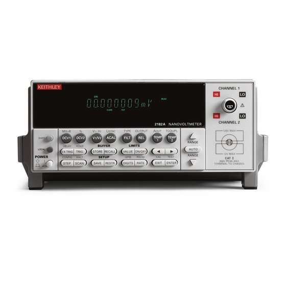
Nanovoltmeter
Brand:
Keithley
| Category:
Measuring Instruments
| Size: 2.07 MB
Table of Contents
Safety Precautions
5
Table of Contents
7
List of Tables
19
Getting Started
23
General Information
25
Warranty Information
25
Contact Information
25
Safety Symbols and Terms
25
Inspection
25
Options and Accessories
26
Nanovoltmeter Features
28
Front and Rear Panel Familiarization
29
Front Panel Summary
29
Figure 1-1 Model 2182 Front Panel
29
Getting Started
30
Getting Started
31
Rear Panel Summary
33
Figure 1-2 Model 2182 Rear Panel
33
Cleaning Input Connectors
35
Power-Up
36
Line Power Connection
36
Figure 1-3 Power Module
36
Setting Line Voltage and Replacing Fuse
37
Power-Up Sequence
37
Table 1-1 Fuse Ratings
37
Line Frequency
38
Display
38
Status and Error Messages
38
Default Settings
38
Table 1-2 Factory Defaults
39
Voltage and Temperature Measurements
41
Measurement Overview
43
Voltage Measurements
43
Temperature Measurements
43
Performance Considerations
45
Warm-Up
45
ACAL (Calibration)
45
Autozeroing Modes
46
LSYNC (Line Cycle Synchronization)
48
Figure
48
Line Cycle Synchronization
48
Pumpout Current (Low Charge Injection Mode)
49
SCPI Programming - ACAL, Front Autozero, Autozero, LSYNC, and Low Charge Injection
50
Connections
52
Connection Techniques
52
Figure 2-2 Model 2107 Input Cable
53
Figure
53
LEMO Connector - Terminal Identification
53
Voltage Only Connections
54
Connections - Single Channel Voltage
54
Figure
54
Figure 2-5 Connections - Dual Channel Voltage
55
Figure 2-6 Connections - Temperature (Internal Reference)
55
Temperature Only Connections
55
Connections - Temperature (Simulated Reference)
56
Connections - Voltage and Temperature (Internal Reference)
56
Cleaning Test Circuit Connectors
57
Figure
57
Figure
56
Voltage and Temperature Connections
56
Connections - Voltage and Temperature (Simulated Reference)
57
Measuring Voltage and Temperature
59
SCPI Programming - Voltage and Temperature Measurements
60
Low-Level Considerations
62
Applications
63
Figure 2-11 Measuring Switch Contact Resistance
64
Figure 2-12 Measuring Switch Contact Resistance and Temperature
65
Figure 2-13 Standard Cell Comparison Measurements
66
Standard Cell Comparisons
66
Heated Zener Reference and Josephson Junction Array Comparisons
67
Range, Digits, Rate, and Filter
69
Range
71
Autoranging
72
Table 3-1 SPCI Commands - Range
72
Table 3-2 SPCI Commands - Digits
73
Figure
74
Speed Vs. Noise Characteristics
74
3 Range, Digits, Rate, and Filter
72
Rate
74
SCPI Programming - Rate
75
Table 3-3 SCPI Commands - Rate
75
Filter
76
Figure 3-2 Moving and Repeating Filters
78
Relative
80
Digital Filter
81
MX+B and Percent (%)
83
Percent (%)
84
SCPI Programming - Relative
86
SCPI Programming - MX+B and Percent
90
Ratio and Delta
91
Ratio
92
Filter, Rel, and Ranging Considerations
94
Delta
96
Figure
97
Test Circuit Using Constant Current Source
97
Figure 5-1 Test Circuit Using Constant Current Source
97
Figure
98
Delta Measurement Using Bipolar Source
98
Figure 5-2 Delta Measurement Using Bipolar Source
98
Selecting Delta
99
Figure
101
Delta Measurement Connections
101
Figure 5-3 Delta Measurement Connections
101
Figure
104
Triggering Timing Diagram
104
Figure 5-4 Triggering Timing Diagram
104
Filter Considerations
105
SCPI Programming - Ratio and Delta
106
Figure
108
Calibrating 1:10 Divider
108
Applications
108
Testing Superconductor Materials
109
Figure
110
Test Circuit-Fixed I (Vary H)
110
Figure 5-6 Test Circuit—Fixed I (Vary H)
110
Figure 5-7 H-V Curve (Fixed I)
111
Figure
111
Sourcemeter Output-2-Point Custom Sweep
111
Figure 5-9 I-V Curve (Fixed H)
112
Figure 5-10 Test Circuit-Fixed H (Vary I)
113
Figure 5-11 Sourcemeter Output-30-Point Custom Sweep
115
Figure 5-12 Trigger Link Connections Using Two Model 2182S
116
Buffer
117
Buffer Operations
118
Figure 6-1 Buffer Locations
119
Recall
119
Buffer Statistics
120
SCPI Programming - Buffer
121
Programming Example
122
Triggering
123
Figure
125
Front Panel Trigger Model (Without Stepping/Scanning)
125
Trigger Model
125
Control Source and Event Detection
126
Table 7-1 Auto Delay Times
126
Figure
127
Device Action
127
Reading Hold (Autosettle)
128
Figure 7-3 Rear Panel Pinout
129
Figure
129
External Triggering
129
Trigger Link Input Pulse Specifications (EXT TRIG)
130
Figure
130
Trigger Link Output Pulse Specifications (VMC)
130
External Trigger
130
7 Triggering
126
DUT Test System
131
Figure
131
Trigger Link Connections
131
External Triggering Example
131
Operation Model for Triggering Example
132
Figure
132
External Triggering with BNC Connections
134
Figure
134
SCPI Programming - Triggering
135
Trigger Model Operation
137
Triggering Commands
138
Programming Example
139
Trigger Model (Remote Operation)
135
Limits
142
Figure 8-1 Default Limits
143
Figure
143
Limit Operations
143
Setting Limit Values
144
SCPI Programming - Limits
145
Setup to Test 10Ω Resistors
147
Application
147
Figure
148
Figure 8-3 Limits to Sort 10Ω Resistors (1%, 5%, and >5%)
148
Limits to Sort 10Ω Resistors (1%, 5%, and >5%)
148
Stepping and Scanning
149
Step/Scan Overview
151
Front Panel Trigger Models
152
Figure
153
Front Panel Triggering (Internal Scanning)
153
Front Panel Triggering (Other Step/Scan Operations)
153
Figure 9-1 Front Panel Triggering (Internal Scanning)
153
Other Stepping/Scanning Operations
154
Stepping/Scanning Examples
156
Internal Stepping
157
External Scanning
158
Figure 9-3 External Scanning Example with Model 7001
159
Figure
159
SCPI Programming - Stepping and Scanning
160
Programming Example
161
Figure 9-4 Waveform to be Programmed into Model 2400
162
Application — I-V Curves Using Internal Scan
162
Setup of Model 2182 and Model 2400
163
Overview
171
Operation
173
SCPI Programming - Analog Output
174
Interfaces
177
Remote Operation
179
Figure 11-1 IEEE-488 Connector
180
Figure
180
GPIB Operation and Reference
180
IEEE-488 Connections
181
Figure
181
IEEE-488 Connector Location
181
Primary Address Selection
182
General Bus Commands
183
Front Panel GPIB Operation
186
Status Structure
187
Figure 11-4 Model 2182 Status Model Structure
188
Figure
188
Figure 12-2 Standard Event Status Register
188
Figure 11-5 Standard Event Status
190
Figure 11-6 Operation Event Status
190
Figure 11-7 Measurement Event Status
191
Figure 11-8 Questionable Event Status
191
Status Byte and Service Request
193
Programming Syntax
195
RS-232 Interface Reference
201
Figure 11-10 RS-232 Interface Connector
203
RS-232 Connections
203
Error Messages
204
Table 11-3 PC Serial Port Pinout
204
Common Commands
206
Figure 12-1 Standard Event Enable Register
209
Figure 12-3 Service Request Enable Register
217
Figure 12-4 Status Byte Register
219
Configure:<Function>
222
Fetch?
223
Measure:<Function>?
224
14 SCPI Reference Tables
226
Table 14-1 Calculate Command Summary
226
Table 14-3 Display Command Summary
226
Table 14-4 Format Command Summary
226
Table 14-6 Route Command Summary
230
Table 14-7 Sense Command Summary
231
Table 14-10 Trace Command Summary
236
Table 14-11 Trigger Command Summary
237
Table 14-12 UNIT Command Summary
238
Additional SCPI Commands
240
Display Subsystem
241
Figure 15-1 ASCII Data Format
242
Format Subsystem
242
Figure 15-2 IEE754 Single Precision Data Format (32 Data Bits)
243
Figure 15-3 IEEE754 Double Precision Data Format (64 Data Bits)
243
Border Command
244
Status Subsystem
245
Figure 15-4 Measurement Event Register
246
Figure 15-5 Questionable Event Register
247
Figure 15-6 Operation Event Register
248
Enable Command
249
Figure 15-7 Measurement Event Enable Register
250
Figure 15-8 Questionable Event Enable Register
250
Condition? Command
251
Preset Command
252
System Subsystem
254
Beeper Command
256
Version? Command
257
KEY <Nrf> Command
258
Figure 15-10 Key-Press Codes
259
Specifications
262
B Status and Error Messages
264
Table B-1 Status and Error Messages
264
Measurement Considerations
269
Measurement Considerations
270
Figure
271
Thermal EMF Generation
271
Thermoelectric Generation
271
Source Resistance Noise
272
Radio Frequency Interference
274
Figure C-2 Power Line Ground Loops
275
Figure C-3 Eliminating Ground Loops
275
Figure C-4 Shielding Example
276
Figure C-5 Meter Loading
277
500 D Model 182 Emulation Commands
280
Table D-1 Model 182 Device-Dependent Command Summary
280
Program Examples
286
One-Shot Triggering
288
Generating SRQ on Buffer Full
289
Storing Readings in Buffer
290
Taking Readings Using the :READ? Command
291
Controlling the Model 2182 Via the RS-232 COM2 Port
292
IEEE-488 Bus Overview
293
Introduction
294
Figure
295
IEEE-488 Bus Configuration
295
Bus Lines
296
Figure
297
Handshake Lines
297
Bus Commands
298
Uniline Commands
299
Universal Multiline Commands
300
Addressed Multiline Commands
301
F IEEE-488 Bus Overview
302
Figure F-3 Command Codes
302
Table F-2 Hexadecimal and Decimal Command Codes
302
Common Commands
302
Table F-3 Typical Addressed Bus Sequence
303
Table F-4 Typical Addressed Common Command Sequence
303
Typical Command Sequences
303
Table F-5 IEEE Command Groups
304
Interface Function Codes
305
G IEEE-488 and SCPI Conformance Information
309
Table G-2 Coupled Commands
309
Fetch?
312
Limitations
313
Sense[1]]:Data:fresh?
314
Examples
315
Delta, Pulse Delta and Differential Conductance
317
Overview
318
Operation Overview
319
Figure I-1 Delta, Pulse Delta, and Differential Conductance Measurements
320
Figure
321
Test System Configurations
321
Test System Configurations
321
Delta Measurement Process
322
Delta Measurement Technique
322
Figure
322
Pulse Delta 3-Point Measurement Technique
325
Pulse Delta Process
325
Figure
327
Pulse Delta Outputs
327
Figure I-5 Pulse Timing
328
Pulse Sweep Output Examples
329
Differential Conductance Process
330
Figure I-7 Differential Conductance Measurement Process
331
Differential Conductance Calculations
332
Configure and Control Analog Output
335
Magnetic Fields
336
Selecting and Configuring an Interface
337
Advertisement
Keithley 2182 Service Manual (120 pages)
Nanovoltmeter
Brand:
Keithley
| Category:
Measuring Instruments
| Size: 2.65 MB
Table of Contents
Safety Precautions
5
Table of Contents
7
List of Illustrations
11
List of Tables
12
1 Performance Verification
14
Introduction
15
Verification Test Requirements
15
Environmental Conditions
15
Warm-Up Period
16
Line Power
16
Recommended Test Equipment
16
Verification Reading Limits
17
Restoring Factory Defaults
17
Auto-Calibration (ACAL)
17
Performing the Verification Test Procedures
18
Test Summary
18
Test Considerations
18
Verification Procedures
19
Voltage Measurement Accuracy
19
Temperature Measurement Accuracy
21
Analog Output Accuracy
23
2 Calibration
26
Introduction
27
Environmental Conditions
27
Temperature and Relative Humidity
27
Calibration Considerations
28
Calibration Cycle
28
Calibration Menu
28
Table 2-1 Calibrating Menu
28
Calibration Errors
30
Aborting Calibration
31
Normal Calibration
31
Recommended Calibration Equipment
31
Front Panel Calibration
31
Remote Calibration
35
Factory Calibration
37
Recommended Test Equipment
37
Remote Factory Calibration
38
Figure 2-3 Connections for Factory DC Volts Calibration
39
Table 2-7 Remote Precalibration Steps
39
Figure 2-4 Low Thermal Short Connections for Factory Calibration
40
Table 2-5 DC Voltage Remote Calibration Programming Steps
40
3 Routine Maintenance
44
Introduction
45
Line Fuse Replacement
45
Figure 3-1 Line Fuse Replacement
45
Line Voltage Selection
46
4 Troubleshooting
48
Introduction
49
Repair Considerations
49
Power-On Self-Test
50
Front Panel Tests
50
KEY Test
50
DISP Test
50
Principles of Operation
51
Power Supply
51
Figure 4-1 Power Supply Block Diagram
51
Figure 4-2 Digital Circuitry Block Diagram
51
Figure 4-3 Simplified Schematic of Analog Circuitry
51
Display Board
52
Digital Circuitry
53
Analog Circuitry
54
Troubleshooting
57
Display Board Checks
57
Table 4-1 Circuit Gain Factors
57
Table 4-2 Display Board Checks
57
Power Supply Checks
58
Table 4-3 Power Supply Checks
58
Digital Circuit Checks
59
Table 4-4 Digital Circuit Checks
59
Analog Circuit Checks
60
Table 4-5 Analog Circuit Checks
60
Analog Signal Switching States
61
Table 4-6 Signal Multiplexing Gain Switching
61
Table 4-7 Input Protection and Low-Noise Preamplifier Analog Switching States
62
No Comm Link Error
63
5 Disassembly
64
Introduction
65
Handling and Cleaning
65
Handling PC Boards
65
Solder Repairs
65
Static Sensitive Devices
66
Assembly Drawings
66
Disassembly
67
Case Cover Removal
67
Motherboard Removal
68
Front Panel Disassembly
68
Main CPU Firmware Replacement
69
Changing Trigger Link Lines
70
Table 5-1 Trigger Link Connections
70
Removing Power Components
71
Power Transformer Removal
71
Power Module Removal
71
Instrument Reassembly
72
Power Module Connections
72
Board Installation
72
6 Replaceable Parts
79
Introduction
80
Parts Lists
80
Ordering Information
80
Factory Service
80
Component Layouts
80
Specifications
92
Noise Performance
93
Analog Output
95
Remote Interface
95
Calibration Reference
96
Introduction
97
Command Summary
98
Default Calibration Constants and Tolerances
99
Miscellaneous Commands
101
Code
101
Count
101
Lock
102
Save
102
Date
103
Ndue
103
Data
104
Calibration Step Commands
104
Precalibration Commands
105
Pcal
105
Detecting Calibration Errors
106
Reading the Error Queue
106
Error Summary
106
Status Byte EAV (Error Available) Bit
107
Generating an SRQ on Error
107
Detecting Calibration Step Completion
108
Using the *OPC Command
108
Calibration Program
110
Introduction
111
Computer Hardware Requirements
111
Software Requirements
111
Calibration Equipment
111
General Program Instructions
112
Keithley 2182 Quick Reference Manual (31 pages)
Nanovoltmeter
Brand:
Keithley
| Category:
Measuring Instruments
| Size: 0.53 MB
Table of Contents
Limitation of Warranty
2
Manual Print History
4
Safety Precautions
5
Measurement Capabilities
8
Front and Rear Panels
8
Basic Connections
9
Model 2107 Input Cable
10
Basic Operation
14
Measurement Considerations
15
Remote Command Programming
15
Programming Examples
16
Settings to Optimize Performance
16
Analog Filter
18
Digital Filter
18
Configuring Filters
18
Features to Enhance DUT Testing
20
Limit Testing
22
Enabling Limits
23
Math Operations
24
Advertisement
Advertisement
Related Products
Keithley 2182A
Keithley SourceMeter 2611
Keithley 2612B
Keithley 2636
Keithley 2635
Keithley TEC SourceMeter 2510-AT
Keithley SourceMeter 2400
Keithley SourceMeter 2420
Keithley SourceMeter 2425
Keithley 2612A
Keithley Categories
Measuring Instruments
Multimeter
Power Supply
Test Equipment
Switch
More Keithley Manuals
Login
Sign In
OR
Sign in with Facebook
Sign in with Google
Upload manual
Upload from disk
Upload from URL