
Related Manuals for Keithley 2182


Summary of Contents for Keithley 2182
- Page 1 Model 2182/2182A Nanovoltmeter Quick Reference Guide 2182A-903-01 Rev. A / June 2004 G R E A T E R M E A S U R E C O N F I D E N C E...
-
Page 2: Limitation Of Warranty
Keithley Instruments, Inc. warrants the following items for 90 days from the date of shipment: probes, cables, software, rechargeable batteries, diskettes, and documentation. During the warranty period, Keithley Instruments will, at its option, either repair or replace any product that proves to be defective. - Page 3 Model 2182/2182A Nanovoltmeter Quick Reference Guide This Quick Reference Guide supports both the Models 2182 and 2182A. References to the Model 2182 also apply to the Model 2182A. ©2004, Keithley Instruments, Inc. All rights reserved. Cleveland, Ohio, U.S.A. First Printing, June 2004...
-
Page 4: Manual Print History
Revision A (Document Number 2182A-903-01) .............. June 2004 All Keithley product names are trademarks or registered trademarks of Keithley Instruments, Inc. Other brand names are trademarks or registered trademarks of their respective holders. -
Page 5: Safety Precautions
Service personnel are trained to work on live circuits, perform safe installations, and repair products. Only properly trained service personnel may perform installation and service procedures. Keithley Instruments products are designed for use with electrical signals that are rated Measurement Category I and Measurement Category II, as described in the International Electrotechnical Commission (IEC) Standard IEC 60664. - Page 6 (note that selected parts should be purchased only through Keithley Instruments to maintain accuracy and functionality of the product). If you are unsure about the applicability of a replacement component, call a Keithley Instruments office for information.
- Page 7 The exact programming syntax will depend on the test program language. NOTE The Model 2182A and later versions of the Model 2182 (firmware version A10 or higher) can be used with the Model 622x to perform Delta and Differential Conductance measurements.
-
Page 8: Measurement Capabilities
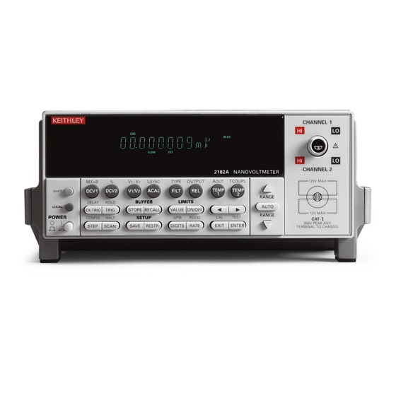
Ratio, delta, mX + b, and percent math operations. Front and rear panels The front and rear panels of the Model 2182 are shown in Figures 1 and 2. The use of the various instrument controls and connectors will be explained throughout this guide. -
Page 9: Basic Connections
Quick Reference Guide Figure 2 Rear panel WARNING: WARNING: NO INTERNAL OPERATOR SERVICABLE PARTS,SERVICE BY QUALIFIED PERSONNEL ONLY. NO INTERNAL OPERATOR SERVICABLE PARTS,SERVICE BY QUALIFIED PERSONNEL ONLY. MADE IN ANALOG OUTPUT U.S.A. 1KΩ OUTPUT RESISTANCE IEEE-488 (CHANGE IEEE ADDRESS FROM FRONT PANEL) TRIGGER LINK RS232... -
Page 10: Model 2107 Input Cable
The red and black wires connect HI and LO of Channel 1, and the green and white wires connect HI and LO of Channel 2. Figure 3 Model 2107 input cable 2182 CHANNEL 1 Model Channel 1... - Page 11 Connections for single channel voltage measurements using a Model 2107 cable to connect Channel 1 are shown in Figure 4. Figure 4 Single-channel measurement connections Cable-to-copper 2107 wire connection Input cable (one of two) DCV1 CH 1 Black Green CH 2 LEAD White Test circuit 2182...
- Page 12 Connections for dual channel voltage measurements using a Model 2107 cable to connect both Channel 1 and Channel 2 are shown in Figure 5. Figure 5 Dual-channel measurement connections Cable-to-copper 2107 wire connection Input cable (one of four) DCV1 CH 1 Black Green CH 2 DCV2 White Test circuit 2182...
- Page 13 Internal reference temperature connections Thermocouple wire soldered directly to LEMO connector (one of two) TEMP1 CH 1 Black Test circuit Thermocouple CH 2 2182 Figure 7 External reference temperature connections Thermocouple 2107 Input cable TEMP1 CH 1 Black Test circuit Green...
-
Page 14: Basic Operation
Observe the voltage reading on the front panel. Making temperature measurements The basic procedure to make temperature measurements is provided in Table 2. It assumes that the DUT is already connected to the Model 2182 as explained in Basic connections. -
Page 15: Measurement Considerations
The :READ? command is typically used to trigger a reading and request the data string. The data string is sent to the computer when the Model 2182 is addressed to talk.The data string can be made of up to three elements separated by commas. The first element is the voltage or temperature reading, the second is the channel, and the third is the units. -
Page 16: Programming Examples
:SENS:VOLT:CHAN1:RANG:AUTO ON Enable channel 1 auto range. :READ? Trigger and acquire one voltage reading. 1. Model 2182 must be addressed to talk after sending :READ? to trigger and acquire data. Table 5 Command sequence for temperature measurement example Command Comments *RST Restore GPIB defaults. - Page 17 5 PLC — Selects the slowest front panel integration time. Selecting 5 PLC (slow) provides better noise performance at the expense of speed. Digits The DIGITS key sets display resolution for the Model 2182. Display resolution for voltage readings can be set from 3 to 7 digits.
-
Page 18: Analog Filter
filter attenuates frequency at 20dB/decade starting at 18Hz. A primary use of the analog filter is to keep the high-gain input stage of the Model 2182 from saturating due to the presence of high AC and DC voltage. Note, however, that the filter only attenuates AC voltages for the 10mV range of the Model 2182. - Page 19 2. 200µsec to 1 sec for 50Hz. 3. Does not include commands to set digital filter parameters. See Section 3 of Model 2182 User’s Manual. 4. Does not include commands to set and acquire rel values. See Section 4 of Model 2182 User’s Manual.
-
Page 20: Features To Enhance Dut Testing
Features to enhance DUT testing Buffer The Model 2182 has a buffer to store from two to 1024 readings and units. It also stores the channel number for step/scan readings and overflow readings. In addition, recalled data includes statistical information (minimum, maximum, peak-to-peak, average, and standard deviation). - Page 21 X i is a stored reading. n is the number of stored readings. NOTE The Model 2182 uses IEEE-754 floating point format for math calculations. Remote buffer programming SCPI commands SCPI commands to configure and control the buffer and buffer statistics are listed in Table 7.
-
Page 22: Limit Testing
:CALC2:STAT ON Enable mean calculation. :CALC2:IMM? Perform calculation and request result.* *Model 2182 must be addressed to talk after sending :TRAC:DATA? and :CALC2:IMM? to acquire data. Limit testing Limit operations set and control the values that determine the HI/IN/LO status of subsequent measurements. -
Page 23: Enabling Limits
Quick Reference Guide Setting limit values To enter high and low limit values, press the Limits VALUE key to view the present HI1 limit value. Use the cursor and RANGE keys to display the desired value, then press ENTER. Repeat the process to set LO1, HI2, and LO2 values. Enabling limits Press the Limits ON/OFF key to view the present beeper status, then change as necessary. -
Page 24: Math Operations
1. Model 2182 must be addressed to talk after sending :READ?, :CALC3:LIM:FAIL?, and :CALC3:LIM2:FAIL? to acquire test result. Math operations Model 2182 math operations include ratio, delta, mX + b, and percent. Ratio Ratio (V1/V2) displays the proportional relationship between the two voltage input channels (DCV1 and DCV2). - Page 25 Delta measurements by the Model 2182 require the use of an alternating polarity source. The source must have external triggering capabilities that are compatible with the external triggering capabilities of the Model 2182. See Section 5 of the Model 2182 User’s Manual for details.
- Page 26 :SENS:VOLT:RATIO ON Enable ratio function. :READ? Trigger and request reading. *Model 2182 must be addressed to talk after sending :READ? to acquire reading. mX+b This math operation manipulates normal display readings (X) mathematically according to the following calculation: Y = mX+b...
- Page 27 Comments :CALC:FORM MXB Select mX+b function. :CALC:KMAT:MMF 2 M = 2. :CALC:KMAT:MBF 0.5 B = 0.5 :CALC:STAT ON Enable mX+b. :CALC:DATA:FRES? Trigger reading and request mX+b result. *Model 2182 must be addressed to talk after sending :CALC:DATA:FRES? to acquire reading.
- Page 28 Quick Reference Guide...
- Page 29 Service Form Model No. Serial No. Date Name and Telephone No. Company List all control settings, describe problem and check boxes that apply to problem. ❏ ❏ ❏ Intermittent Analog output follows display Particular range or function bad; specify ❏ ❏...
- Page 30 M E A S U R E C O N F I D E N C E Keithley Instruments, Inc. Corporate Headquarters • 28775 Aurora Road • Cleveland, Ohio 44139 • 440-248-0400 • Fax: 440-248-6168 • 1-888-KEITHLEY • www.keithley.com 12/06...
Need help?
Do you have a question about the 2182 and is the answer not in the manual?
Questions and answers