Table of Contents
Advertisement
Quick Links
Advertisement
Table of Contents

Related Manuals for IBM TotalStorage 3494 Tape Library


Summary of Contents for IBM TotalStorage 3494 Tape Library
- Page 1 IBM TotalStorage 3494 Tape Library Operator Guide GA32-0449-14...
- Page 3 IBM TotalStorage 3494 Tape Library Operator Guide GA32-0449-14...
- Page 4 “Notices” on page 547. This Edition This edition applies to the IBM TotalStorage 3494 Tape Library and to all subsequent releases and modifications until otherwise indicated in new editions. This edition replaces GA32-0449-13. © Copyright International Business Machines Corporation 2001, 2008. All rights reserved.
-
Page 5: Table Of Contents
. 41 Database Information Available to a Host . . 42 Safety and Environmental Notices . . xiii IBM TotalStorage 3494 Tape Library Specialist . . 42 Safety and Environmental notices and publication Operational Modes and States . . 43 information . - Page 6 Operator Involvement . . 79 Shutdown State to Library Manager System Administrator Involvement . 80 Initialization State . . 108 Error Detection and Reporting . . 80 Library Manager Initialization State to Inventory Update . . 81 Initialization Complete State . .
- Page 7 Lockup Library Manager . 152 Stand-Alone Device . . 330 Shutdown . 152 Insert Unlabeled Cartridges . 336 Online Shutdown . . 153 LAN Options . . 338 Using the Status Menu . . 156 Operator Intervention . 353 Operational Status . .
- Page 8 Quick Reference to Problem Determination Appendix A. Keyboard Template . . . 511 Procedures . . 433 Failure and Exception Condition Reporting . . 434 Appendix B. VTS Export and Import Library Manager Failure Recovery Procedures . . 435 Advanced Function ..513 Library Manager Failure in DFSMS/MVS Export and Import List Volumes Format .
-
Page 9: Figures
80. 3494 Tape Library Shutdown Window 35. Library Manager (before October 29, 2004) 81. Shutdown Request Window 1 . . 154 36. 3494 B18, B10, and B20 VTS - Operator Panel 82. System Administrator Password Window © Copyright IBM Corp. 2001, 2008... - Page 10 83. Shutdown Request Window 2 . . 155 134. Commands Menu . . 223 84. Library Shutdown Window . . 155 135. Clean Schedule Window — Timed Clean 85. Shutdown Library Manager Window 136. Clean Schedule Window — Usage Clean 86.
- Page 11 190. VPD Summary/Code Load/Dev Reset - 3592 237. Options Menu . . 384 History Details . . 302 238. Mode Menu . . 386 191. Verify Fix Diagnostics window . . 304 239. Mode/State Change Request Window 192. Queue a Clean Mount for Device Window 240.
- Page 12 277. Window List . . 430 281. DCAF Password . 432 278. Active Session . . 430 282. Library Manager Switching Window 279. Changing Sessions . . 431 283. Library Manager Switching Window 280. Options Menu . . 431 284. Status Flags . .
-
Page 13: Tables
Cartridge Tape Labeling (3490E & 3590 Tape DFSMS Messages Based on Library Failure or Drives) . . 26 Exception Conditions . . 443 IBM Total Storage Enterprise Tape Cartridge Problem Determination Using System 3592 types . . 28 Summary Window . . 453... - Page 14 3494 Tape Library Operator Guide...
-
Page 15: Safety And Environmental Notices
Most danger or caution notices contain a reference number (Dxxx or Cxxx). Use the reference number to check the translation in the IBM Systems Safety Notices, G229–9054 manual. The sections that follow define each type of safety notice and give examples. -
Page 16: Environmental Notices
MRU. Use handholds as instructed by service procedures. (C016) Caution Do not connect an IBM control unit directly to a public optical network. The customer must use an additional connectivity device between an IBM ®... - Page 17 IBM recomienda a los propietarios de equipos de tecnología de la información (TI) que reciclen responsablemente sus equipos cuando éstos ya no les sean útiles. IBM dispone de una serie de programas y servicios de devolución de productos en varios países, a fin de ayudar a los propietarios de equipos a reciclar sus productos de TI.
- Page 18 United States, go to http://www.ibm.com/ibm/ environment/products/index.shtml or contact your local waste disposal facility. In the United States, IBM has established a return process for reuse, recycling, or proper disposal of used IBM sealed lead acid, nickel cadmium, nickel metal hydride, and other battery packs from IBM Equipment.
- Page 19 For proper collection and treatment, contact your local IBM representative. Spain This notice is provided in accordance with Royal Decree 106/2008 of Spain: The retail price of batteries, accumulators and power cells includes the cost of the environmental management of their waste.
-
Page 20: Laser Safety And Compliance
This machine may contain an optional feature, the cryptographic coprocessor card which includes a polyurethane material that contains mercury. Please follow Local Ordinances or regulations for disposal of this card. IBM has established a return program for certain IBM Cryptographic Coprocessor Cards. More information can be found at http://www.ibm.com/ibm/environment/products/recycling.shtml... -
Page 21: Class I Laser Product
necessary protective housings and scanning safeguards to ensure that laser radiation is inaccessible during operation or is within Class II limits. These products have been reviewed by external safety agencies and have obtained approvals to the latest standards as they apply to this product type. Class I Laser Product The 3494 Tape Library contains a laser assembly that complies with the performance standards set by the U.S. - Page 22 3494 Tape Library Operator Guide...
-
Page 23: About This Publication
Who Should Read This Book This book is intended for operators of the 3494 Tape Library. Users of this information should be familiar with the IBM 3490E, 3590, and 3592 magnetic tape subsystems. IBM recommends that you also read the IBM TotalStorage 3494 Tape Library Introduction and Planning Guide. -
Page 24: Ibm 3490E Tape Subsystem
IBM System Storage TS1120 and TS1130 Tape Drives and TS1120 Controller Introduction and Planning Guide, GA32-0555 v IBM System Storage TS1120 and TS1130 Tape Drives and TS1120 Controller Operator Guide, GA32–0556 ® The following publications relate to the AIX systems and software environment: v Parallel and ESCON Channel Tape Attachment: Installation and User’s Guide,... -
Page 25: Ibm As/400 And Ibm Erserver Iseries
™ The following publications relate to the VSE/ESA systems and software environment: v IBM 3494 User’s Guide: Device Driver VSE/ESA, GC35-0176 v VSE/ESA System Control Statements, SC33-6613 Additional Information The following publications contain additional information that relates to the 3494... -
Page 26: Send Us Your Feedback
Send us your feedback Your feedback is important to us. Send us your comments by e-mail to starpubs@us.ibm.com or use the Readers’ Comments form at the back of this publication. Be sure to include the following: v Exact publication title... -
Page 27: Chapter 1. Introduction
Chapter 1. Introduction This chapter contains an introduction and a description of the 3494 Tape Library. Note: The IBM 3494 Tape Library Operator Training Video Tape and the IBM 3494 Tape Library Operator’s Quick Guide are supplied with accessories. Summary of Changes for September 2008 Revision bars (|) appear in the left margin adjacent to information that is new or has changed since the previous edition of this manual, GA32-0449-13. - Page 28 - IBM TotalStorage 3590 Tape Drive Model B1A (3590 B1A Tape Drive) or IBM TotalStorage 3590 Tape Drive Model E1A (3590 E1A Tape Drive) (3494 L12 Frame or 3494 L14 Frame) - IBM TotalStorage 3590 Tape Drive Model H1A (3590 H1A Tape Drive) (3494...
- Page 29 VTS. They also provide host system ESCON or Fiber Connection (FICON) attachments. v The optional IBM TotalStorage 3494 Tape Library Frame Model S10 (3494 S10 Frame) 6 contains additional cartridge storage only. v The optional IBM TotalStorage 3494 High Availability Option HA1 (3494 HA1 Option) service bays (left 2 and right 7 ) contain service areas for the cartridge accessors.
-
Page 30: Functional Components
Without the 3494 HA1 Option Figure 2. 3494 Tape Library Configurations Note: For additional 3494 Tape Library configurations, see the IBM TotalStorage 3494 Tape Library Introduction and Planning Guide. The 3494 Lxx Frame provides full library function without the other optional frames. - Page 31 2 Tape Drives The 3494 Tape Library uses the following tape drives: v 3490E C1A, C2A, (see Figure 3 on page 6) or F1A (not shown) Tape Drives v 3590 B1A Tape Drives or 3590 E1A Tape Drives, with or without a 3590 A00, A50, or A60 Controller or a 3592 J70 Controller v 3590 H1A Tape Drives, with or without a 3590 A60 Controller or a 3592 J70 Controller...
-
Page 32: L10 Frame Functional Components, 3490E
Figure 3. 3494 L10 Frame Functional Components, 3490E (Front View) Figure 4. 3494 L12 Frame Functional Components, 3590 (Front View) 3494 Tape Library Operator Guide... -
Page 33: L22 Frame Functional Components
Figure 5. 3494 L22 Frame Functional Components, 3592 (Front View) Figure 6 on page 8 shows the rear of the 3494 Lxx Frame, with the following functional components: 1 Library Manager The Library Manager controls all operations in the 3494 Tape Library. Its hardware consists of a controller, display, pointing device, and keyboard. -
Page 34: L14 Frame Functional Components (Rear View)
Figure 6. 3494 L14 Frame Functional Components (Rear View) Figure 7 on page 9 shows the front of the 3494 S10 Frame , with the following functional components: 1 Cartridge Storage Cells The cells are located on the inside of the front door and on the back wall of the 3494 S10 Frame. -
Page 35: S10 Frame Functional Components (Front View)
Figure 7. 3494 S10 Frame Functional Components (Front View) Figure 8 on page 10 shows the front of the 3494 Dxx Frame. This example shows four 3590 B1A, E1A, or H1A tape drives, a 3590 A00, A50, or A60 Controller or a 3592 J70 Controller, and the following functional components: 1 Cartridge Storage Cells The cells are located on the inside of the front door and on the back wall... -
Page 36: Dxx Frame Functional Components
Figure 8. 3494 Dxx Frame Functional Components (Front View) Figure 9 on page 11 shows the rear (without the rear door) of the 3494 D1x Frame. This example shows four 3590 B1A, E1A, or H1A tape drives, a 3590 A00, A50, or A60 Controller or 3592 J70 Controller, and the following functional components: 1 Cartridge Storage Cells The cells are located on the inside of the front door and on the back wall... -
Page 37: D14 Frame Functional Components
Figure 9. 3494 D14 Frame Functional Components (Rear View) Figure 10 on page 12 shows the rear (without the rear door) of the 3494 D2x Frame. This example shows eight 3592 Tape Drives, a 3592 J70 Controller, and the following functional components: 1 Cartridge Storage Cells The cells are located on the inside of the front door and on the back wall of the 3494 D2x Frame. -
Page 38: D2X Frame Functional Components
Figure 10. 3494 D2x Frame Functional Components (Rear View) Figure 11 on page 13 shows the upper portion of the 3494 D2x Frame with exterior panels removed. This view shows the following functional components: 1 2 Gb and 4 Gb Fibre Channel Switches The 2 Gb and 4 Gb fibre channel switches provide attachment of up to sixteen 3592 Tape Drives. -
Page 39: D2X Frame Functional Components
Figure 11. 3494 D2x Frame Functional Components (Upper Portion) Figure 12. 3494 B16 VTS Functional Components (Front View) Figure 13 on page 14 shows the rear (without the rear door) of the 3494 B16 VTS, with the following functional components: Chapter 1. -
Page 40: B16 Vts Functional Components
1 Cartridge Storage Cells The cells are located on the inside of the front door and on the back wall of the 3494 B16 VTS. 2 Rail System The rail system carries the cartridge accessor through the 3494 Tape Library. The rail system consists of two horizontal rails, one at the top and one at the bottom of the 3494 B16 VTS. -
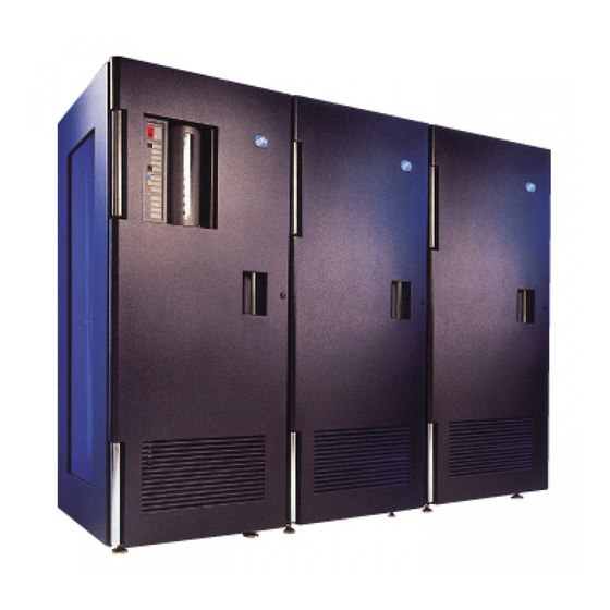
Page 41: B18, B10, And B20 Vts (Front View)
Figure 14. 3494 B18, B10, and B20 VTS (Front View) Figure 15 on page 16 shows the rear (without the rear door) of the 3494 B18, B10, and B20 VTS, with the following functional components: 1 Disk Storage Disk storage holds the contents of the tape volume cache. The VTS controller manages the disk storage. -
Page 42: B18, B10, And B20 Vts Functional
Figure 15. 3494 B18, B10, and B20 VTS Functional Components (Rear View) Figure 16 on page 17 shows the front of the 3494 CX0 and CX1 Frame. 3494 Tape Library Operator Guide... -
Page 43: Cx0 And Cx1 Frame (Front View)
Figure 16. 3494 CX0 and CX1 Frame (Front View) Figure 17 on page 18 shows the rear (without the rear door) of the 3494 CX0 Frame, with the following functional components: 1 3494 AX0 VTCs Two or four 3494 AX0 VTCs may be installed in the 3494 CX0 Frame. The 3494 AX0 VTCs provide interconnection between the 3494 B18, B10, and B20 VTSs and host system ESCON attachments. -
Page 44: Cx0 Frame Functional Components
Figure 17. 3494 CX0 Frame Functional Components (Rear View) Figure 18 on page 19 shows the rear (without the rear door) of the 3494 CX1 Frame, with the following functional components: 1 VTCs Two or four VTCs may be installed in the 3494 CX1 Frame. The VTCs provide interconnection between the 3494 B18, B10, and B20 VTSs and host system FICON (3494 B10 and B20 VTS only) and/or ESCON attachments. -
Page 45: Cx1 Frame Functional Components
Figure 18. 3494 CX1 Frame Functional Components (Rear View) Figure 19 on page 20 shows the right-front of the 3494 HA1 Option, left service bay, with the following functional components: 1 Cartridge Storage Cells The cells are located on the inside of the front doors and on the back walls of the 3494 HA1 Option. -
Page 46: Ha1 Option, Left Service Bay Functional
Figure 19. 3494 HA1 Option, Left Service Bay Functional Components (Right-Front View) Figure 20 on page 21 shows the left-front of the HA1 Frame right service bay frame, with the following functional components: 1 Cartridge Storage Cells The cells are located on the inside of the front doors and on the back walls of the 3494 HA1 Option. -
Page 47: Cartridge I/O Facilities
Figure 20. 3494 HA1 Option, Right Service Bay Functional Components (Left-Front View) Cartridge I/O Facilities The following types of input and output facilities are available in the 3494 Tape Library: v High-Capacity Output facility v High-Capacity I/O facility v Single-Cell Output facility v Convenience I/O Station feature High-Capacity Output Facility The high-capacity output facility, if defined during installation, reserves a section... -
Page 48: Single-Cell Output Facility
(whole wall) cells. A 3494 Dxx Frame configured as high-capacity I/O contains from 50 (six 3590 drives) to 135 (two 3590 drives) cells. It uses all available cells in the wall. Only a single wall can be configured at any time (single high-capacity I/O facility). -
Page 49: Tape Storage Media
Tape Storage Media Note: 1. Cartridge tape is the term used for 3490E & 3590 tape storage media. 2. Tape cartridge is the term used for 3592 tape storage media. 3. Cartridge is the generic term used when referring to any tape storage medium used in the 3494 Tape Library. -
Page 50: E And 3590 Cartridge Tape Requirements
Do not write-protect scratch cartridges as new data cannot be written to write-protected cartridges. For additional information, see Care and Handling of the IBM Magnetic Tape Cartridge. Cartridge Tape Labels (3490E and 3590 Tape Drives) Each cartridge tape in the 3494 Tape Library must have external labels that are operator- and device-readable. - Page 51 The external labels on the cartridges identify the cartridges to the 3494 Tape Library. Host control software in some operating environments requires that internally written labels on volumes correspond to external volsers. IBM recommends that correspondence of external and internal cartridge labels be verified by library control software as part of mount processing.
-
Page 52: Cartridge Tape Labels
Blue Green Gray Gray Gray White Gray White Black Black Figure 24. Cartridge Tape Labels (3490E and 3590 Tape Drives) Table 1. Cartridge Tape Labeling (3490E & 3590 Tape Drives) Media-Type Cartridge Type Color Label Processed as: 1 - Cartridge System Tape Gray Not present Cartridge System Tape... -
Page 53: Tape Cartridges (3592 E06, Eu6, E05, And J1A Tape Drives)
See examples 2 , 4 , 5 , and 6 in Figure 24 on page 26. The label must be flat to within 0.5 mm (0.02 in.) over the length of the label and have no folds, missing pieces, or smudges. The label must not be rotated more than 3°... -
Page 54: Tape Cartridge Identification
*1P000002JA Platinum Case Dark green write-protect switch Figure 25. 3592 Tape Cartridge Identification Table 2 summarizes the characteristics of the 3592 tape cartridges. Table 2. IBM Total Storage Enterprise Tape Cartridge 3592 types Name Type Native Native Native Case Label,... - Page 55 Table 2. IBM Total Storage Enterprise Tape Cartridge 3592 types (continued) | | | | | | DATA 300 GB 500 GB 640 GB Black Dark Blue 18P7534 (MEDIA5) | | | | | EXTENDED 700 GB 1000 GB Black...
-
Page 56: Tape Cartridge Requirements
Do not write-protect scratch cartridges as new data cannot be written to write-protected cartridges. For additional information, see Care and Handling of the IBM Magnetic Tape Cartridge. Tape Cartridge Bar Code Labels (3592 Tape Drives) Each tape cartridge in the 3494 Tape Library must have an external bar code label that is operator- and device-readable. - Page 57 Figure 27 on page 32). Note that host control software in some operating environments requires that internally written labels on volumes correspond to external volsers. IBM recommends that correspondence of external and internal cartridge labels be verified by library control software as part of mount processing. Cleaner cartridges must also have operator- and device-readable external labels to identify each cartridge.
-
Page 58: Tape Cartridge Labels
*1P000002JA Black Case Dark blue write-protect switch *1P000002JA Black Case Light blue write-protect switch *1P000002JA Platinum Case Light blue write-protect switch *1P000002JA Platinum Case Dark blue write-protect switch *1P000002JA Black Case Dark green write-protect switch *1P000002JA Platinum Case Dark green write-protect switch Figure 27. -
Page 59: Use Of Non-Ibm-Standard Media Labels
Telephone: 61 (0) 2 4577 3793 Fax: 61 (0) 2 4577 4357 http://www.netclabels.com.au Use of Non-IBM-Standard Media Labels Standard IBM media labels are described in Table 4. Table 4. Standard IBM Media Labels Cartridge Type Character(s) Label Description Cartridge Type... - Page 60 The 3494 Tape Library uses a volser range table to allow cartridges of different types with non-IBM-standard labels to be recognized. The volser range table allows an operator to associate a cartridge type with a range of volsers. If a cartridge isn’t labeled, the Library Manager examines the volser range table to determine whether the volser range of the cartridge falls into one of the defined ranges.
-
Page 61: Unlabeled Tape Facility
Cartridges with non-IBM-standard media labels can be inserted into either the I/O station, the High Capacity I/O Facility, or into empty cartridge storage cells. Note that Inventory Update must be run after inserting the cartridges into empty cartridge storage cells. -
Page 62: Cartridge Bar Code Label Guidelines
or from the bottom. Carefully position the label within the indentation on the end of the cartridge away from the leader block. The device-readable bar code must face to the right. 4. Apply the label parallel to the long edge of the indentation. Do not pull the label excessively because it will stretch. -
Page 63: Cartridge Storage Cells
Cartridge Storage Cells The names of the cartridge cell locations allow you to find the cartridges during Manual mode operation. The cell name consists of three values: a wall number, a column letter, and a row number. For example, Figure 29 shows cell location 2 A 1. Figure 29. -
Page 64: Reserved Cartridge Storage Cells
Figure 30. Cartridge Storage Cell Labeling Reserved Cartridge Storage Cells The 3494 Tape Library reserves certain cartridge storage cells for functions that you do not control actively. In frames other than the 3494 HA1 Option, these locations are Error Recovery Cells 1 A 1 (if the optional Dual Gripper feature is installed, 1 A 3 instead of 1 A 1) and CE cartridge cell 1 A 20. -
Page 65: Drives)
Table 5. 3494 Tape Library Cartridge Capacity (continued) Model or Frame Without Dual Gripper With Dual Gripper 3494 D10 Frame (without Model CxA or F1A Tape Drives) 3494 D10 Frame (with 3490E CxA or F1A Tape Drives) 3494 D12 Frame 3494 D12 Frame (without 3590 B1A, E1A, or H1A tape drives) 3494 D12 Frame (with one or two 3590... -
Page 66: Library Manager
You can also access the Library Manager from a remote location. For information on how to do this, see Chapter 7, “Remote Library Manager Console Feature,” on page 417 or “IBM TotalStorage 3494 Tape Library Specialist” on page 42. Password Protection Password protection for the level of authorization is optional. -
Page 67: Database
Service representative The service representative has full authorization access to all functions of the 3494 Tape Library. If you choose to use password protection, the password can protect the following functions of the Library Manager: v Service menu v Inventory new storage v Reinventory complete system v Emergency power off (EPO) recovery v Shutdown... -
Page 68: Database Information Available To A Host
Information about the category attributes, for example, the name. IBM TotalStorage 3494 Tape Library Specialist The IBM TotalStorage 3494 Tape Library Specialist (Specialist) is a Web-based user interface to the Library Manager. Using the Specialist, you can access information such as current 3494 Tape Library status and VTS statistics from your Web browser by connecting to the Web server on the Library Manager PC. -
Page 69: Operational Modes And States
through the Remote Service Access connection over a modem. For detailed information on the functions and features of the Specialist, see “3494 Tape Library Web Interfaces” on page 396. The minimum requirements to use the Specialist are as follows: v 64 MB of RAM v Functional code of 524 or greater The Specialist feature is already on your 3494 Tape Library. -
Page 70: Ts1120 Model C06 Controller Adjacent Frame Support
This feature allows two frames to be “linked” together. The frames are “linked” during the teach operation, which the service representative performs during installation. The linked frames must be adjacent to one another. TS1120 Model C06 Controller Adjacent Frame Support 3592 Tape Drives installed in an adjacent 3494 D22 Frame, 3494 D24 Frame, or 3494 L22 Frame can be attached to the TS1120 (C06) Controller mounted in the outbound 3952 Tape Frame. - Page 71 TS1120 (C06) Controller v Library Manager, if attached to a 3590 A60 Controller, 3592 J70 Controller, TS1120 (C06) Controller, or VTS that supports Call Home, or directly to a IBM System Storage TS3000 System Console (TSSC) Status information is transmitted to the IBM Support Center for problem evaluation;...
- Page 72 3494 Tape Library Operator Guide...
-
Page 73: Chapter 2. Controls And Indicators
The front door of the 3494 Lxx Frame holds the operator panel. You control normal operation of the 3494 Tape Library with this panel. Power Controls and Power Status LEDs See Figure 32 on page 49 for the locations of the power controls and power status LEDs. © Copyright IBM Corp. 2001, 2008... -
Page 74: Motion Control Switches And Status Leds
1 Unit Emergency switch Setting the Unit Emergency switch to O (OFF) powers off the 3494 Tape Library immediately. Use this switch only in an emergency. Do not use it to power on or power off the 3494 Tape Library. Sudden removal of power in case of emergency may cause loss of data. -
Page 75: Convenience I/O Station Status Leds
Pause mode. The Pause LED flashes during the mode transition and remains lit when in Pause mode. If the mode transition cannot be completed, the Intervention Required LED lights. 9 Intervention Required LED The Intervention Required LED, when lit, indicates that operator intervention is required. -
Page 76: Library Manager
5 Convenience I/O Station Operation Tab The convenience I/O station operation tab is used to open the convenience I/O station door when the door is unlocked (when the I/O Locked status LED is not lit). Figure 33. 3494 Lxx Frame - Operator Panel with Convenience I/O Station Feature Library Manager The Library Manager display 1 (see Figure 35 on page 51 or Figure 34 on page 51) and keyboard (with its pointing device) 2 are located in the rear of the L... - Page 77 See “Selecting with the Pointing Device” on page 133 for a detailed description on using the pointing device. The 3494 HA1 Option, service bay B, is similar in looks and function. Figure 34. Library Manager (after October 29, 2004) Figure 35. Library Manager (before October 29, 2004) Chapter 2.
-
Page 78: B16 Vts Controls
3494 B16 VTS Controls All control functions for the 3494 B16 VTS are integrated into the Library Manager (see Chapter 6, “Advanced Operating Procedures,” on page 125). 3494 B18, B10, and B20 VTS Operator Panel The rear door of the 3494 B18, B10, and B20 VTSs holds the operator panel. Figure 36 shows the location of the power control on the operator panel of the 3494 B18, B10, and B20 VTSs. -
Page 79: 3494 Cx0 And Cx1 Frame Operator Panel
3494 CX0 and CX1 Frame Operator Panel The rear door of the 3494 CX0 and CX1 Frame holds the operator panel. Figure 37 shows the location of the power control on the operator panel of the 3494 CX0 and CX1 Frame. 1 Unit Emergency switch Setting the Unit Emergency switch to the O (OFF) position powers off the 3494 CX0 and CX1 Frame and all of its internal components immediately. -
Page 80: B1A, E1A, H1A Tape Drive Controls
Controller, 3592 J70 Controller, or TS1120 (C06) Controller to send information to the host. For more information on 3592 controls and indicators, see the IBM TotalStorage Enterprise Tape System 3592 Operator Guide, GA32–0465. 3590 B1A, E1A, H1A Tape Drive Controls... -
Page 81: C1A, C2A Tape Drive Controls
The Library Manager can use the communication path to the 3590 A00, A50, or A60 Controller to send information to the host. For more information on 3590 controls and indicators, see the IBM TotalStorage Enterprise Tape System 3590 Operator Guide. -
Page 82: F1A Tape Drive Controls
The Library Manager can use the communication path to the 3490E subsystems to send information to the host. For more information on 3490E Model CxA controls and indicators, see the IBM 3490 Magnetic Tape Subsystem Enhanced Capability Models C10, C11, C1A, C22, and C2A Operator’s Guide. -
Page 83: E Model F1A - Controls And Indicators
The Library Manager can use the communication path to the 3490E subsystems to send information to the host. For more information on 3490E Model F1A controls and indicators, see the IBM 3490E Tape Subsystem Models F01, F1A, F11, and FC0 Installation, Planning, and Operator’s Guide. - Page 84 3494 Tape Library Operator Guide...
-
Page 85: Chapter 3. Operational Characteristics
The TS7700 Virtualization Engine consists of several primary components that can be described in terms of their system role or according to their technical functions. See the IBM Virtualization Engine TS7700 Information Center at http:// publib.boulder.ibm.com/infocenter/ts7700ic/v1r0/index.jsp for complete details about using the TS7700 Virtualization Engine. -
Page 86: Vnode, Hnode, And Gnode Construction
vNode vNode vNode Controller gNode hNode hNode hNode Controller Controller Figure 42. vNode, hNode, and gNode construction The TS7700 Virtualization Engine Cluster combines the virtualization engine with a disk subsystem, the TS7740 Cache Controller. This architecture will allow additional disks or nodes to be added in future offerings to expand the capabilities of the system. -
Page 87: Ts7700 Virtualization Engine Two-Cluster Grid
two-Cluster TS7700 Virtualization Engine Grid configuration. Cluster Cluster TS7700 Virtualization Engine Grid Figure 44. TS7700 Virtualization Engine two-cluster Grid configuration Operational Components Figure 45 on page 62 shows the major operational components of the TS7700 Virtualization Engine, configured as a gNode. Chapter 3. -
Page 88: Ts7700 Virtualization Engine
Ethernet and fibre adapters for Grid configuration connection. IBM Virtualization Engine TS7740 CC6 (TS7740 Cache Controller or 3956-CC6) The TS7740 Cache Controller consists of a redundant array of independent disks (RAID) disk controller and associated disk storage media. These media act as cache storage for customer data. -
Page 89: Attachment To The 3494 Tape Library
Library Manager and tape drives The 3494 Tape Library contains an internal Library Manager; there is no need for an external Library Manager as there is for the IBM System Storage TS3500 Tape Library (TS3500 Tape Library). Communication and control signals travel among... -
Page 90: Encryption Overview
IBM Encryption Key Manager component for the Java platform Introduction, Planning, and User’s Guide, GA76-0418 v IBM TotalStorage 3494 Tape Library Maintenance Information and IBM 7581 Library Manager Console Maintenance Information for information about installing an encryption-capable drive in a IBM TotalStorage 3494 Tape Library. -
Page 91: Establishing An Encryption Policy
Attention: There is no recovery for lost encryption keys. To set up and use encryption in the 3494 Tape Library, perform the following tasks. Note: In some instances IBM Systems Services Representative (SSR)s will be required to enable encryption at a hardware level when service access or service password controlled access is required. -
Page 92: Virtual Tape Server
- 3592 (Service Representative)” on page 303. To rekey a cartridge for extra protection or for reuse, see “Setup Stand-Alone Device” on page 330. Virtual Tape Server See the IBM Virtualization Engine TS7700 Information Center at http:// publib.boulder.ibm.com/infocenter/ts7700ic/v1r0/index.jsp for complete details about using the TS7700 Virtualization Engine. -
Page 93: Emulation Of 3490E Tape Drives
Emulation of 3490E Tape Drives From a host perspective, the VTS subsystem looks like two, four, eight, or sixteen 3490E control units, each with 16 tape drives. Each emulated drive is called a virtual tape drive. The subsystem handles all 3494 Tape Library tape commands. Emulating a 3490E-type tape drive eliminates the need for host software support of a new type of tape drive in order to utilize the capacity of 3590- and 3592-type tape drives. -
Page 94: Storage Management Of The Tape Volume Cache
Storage Management of the Tape Volume Cache Storage management software manages the contents of the tape volume cache. Virtual tape volumes are copied from the tape volume cache to physical tape when the virtual volume has been closed, and they are recalled from tape to the tape volume cache when they are again requested to be mounted. -
Page 95: Advanced Policy Management
cartridge through the convenience I/O station for storage outside the 3494 Tape Library or movement to another 3494 Tape Library to be imported into a VTS. Host console messages provide status on progress and success of the Export operation. Note: 1. - Page 96 The key elements of Advanced Policy Management are storage management constructs and storage pools. Storage Management Constructs Storage management constructs are user-defined groupings used to define actions for logical volumes. Each construct type can have a maximum of 256 names including the default name.
- Page 97 VE Clusters Used to enter or view the cluster copy data consistency point values for each cluster of the IBM Virtualization Engine TS7700 Series. Clicking on the Open Panel button brings up the Cluster Copy Data Consistency Point panel (Figure 160 on page 259) that is used to change or view the consistency point values on a per-virtualization engine basis.
-
Page 98: Storage Pools
Storage Class Used to define the Tape Volume Cache (TVC) preference for a logical volume. The Tape Volume Cache (TVC) preference level has 3 options. v Use the TVC preference as defined by the IART value specified by the host to the VTS. Using this option eases the customer’s migration from using the already implemented IART method to using the Storage Class construct to define the TVC preference levels. -
Page 99: Bulk Volume Information Retrieval
Normally, the first few records on a tape contain a tape volume label, and enough data records are maintained to contain an IBM standard tape label plus any unique user label records. -
Page 100: Deletion Of Vts Logical Volumes
the next available volume assigned to the specified category to satisfy the host request. Within a VTS, the data fragment is used in conjunction with a mount from category request to provide very fast response times for nonspecific mounts. Categories used for nonspecific mounts are defined through the Library Manager as “Fast Ready”... - Page 101 private status restores access to the data. This benefit does have a cost. These user expired logical volumes needlessly consume physical stacked volume resources, thus requiring more physical stacked volumes in a VTS. Also, since these volumes are still considered active, the time until a physical volume falls below the reclamation threshold is increased and potentially, expired data will be moved during a reclaim.
-
Page 102: Scratch Stacked Volumes
In setting up a PtP VTS and when using the delete expired volume data function, the following considerations apply depending on the I/O selection mode of operation. v For No Preference Ensure that the non-zero expire time on both library managers is set to the same value. -
Page 103: Escon Host Attachment
v Logical library partitioning v Operator interface v Logical volume inventory Logical Library Partitioning To support the product requirement that a VTS can coexist with current 3490 tape drives and native 3590 or 3592 tape drives in the same 3494 Tape Library, the Library Manager partitions the physical library into logical libraries. -
Page 104: Ficon Host Attachment
1 Gbps speed, please contact an IBM service representative. An example of when this would be required is if you are using a 2 Gbps channel with a cable length that is only supported for 1 Gbps. -
Page 105: Local And Remote Power Control
The PtP VTS provides a Web interface, the IBM TotalStorage PtP VTS Specialist, that allows you to connect to the Web server on the 3494 AX0 VTCs or VTCs to access information about the PtP VTS. -
Page 106: System Administrator Involvement
Operator assistance is required if an error or exception condition occurs from which the 3494 Tape Library cannot recover on its own. Depending on the type of error or exception condition experienced, some or all of the 3494 Tape Library operations are suspended until the problem is corrected. -
Page 107: Inventory Update
Inventory Update When Inventory Update is enabled and a door is opened, then closed, an inventory update is performed upon the return to Auto mode. This process checks all of the cartridge storage cells in the frames that had doors opened, and depending on the selection made during the teach process, may also check any frames adjacent to the frames that had doors opened. -
Page 108: Volume Categories
v If an unlabeled cartridge is found, the cartridge is ejected from the library unless the unlabeled cartridge was inserted by using the Unlabeled Tape facility and the unlabeled cartridge is found in its home cell. See “Insert Unlabeled Cartridges” on page 336 for information regarding the use of unlabeled cartridges. - Page 109 Table 8. Volume Categories (continued) Category (in hex) Name Definition FF03 VTS Scratch The VTS assigns stacked volumes that are scratch in the VTS to this category. This category is not used if licensed internal code is 527 or higher. The TS7700 Virtualization Engine does not use the FF03 category to track physical scratch volumes.
- Page 110 Table 8. Volume Categories (continued) Category (in hex) Name Definition FF11 Bulk eject Set when a Library Manager accepts an eject request. The volume becomes eject pending, and the 3494 Tape Library queues the volume to be moved to the high-capacity output facility.
- Page 111 Table 8. Volume Categories (continued) Category (in hex) Name Definition FF17 Export-Hold The VTS assigns Exported Stacked Volumes to this category. This is a “limbo” category where export volumes are placed when the Export operation is completed. The operator uses the Manage Export-Hold Volumes window, shown in Figure 153 on page 253, to cause volumes in this category to be ejected.
-
Page 112: Physical Volume States
Table 8. Volume Categories (continued) Category (in hex) Name Definition FFF9 Service volume, Set when the Library Manager detects that a volume 3490E only has a unique service volser. Volsers that fit the mask CE xxx (where xxx represents any valid volser characters) are service volumes. -
Page 113: Logical Volume States
Misplaced A volume is in the inventory, and the Library Manager determines that it is not in the position that the inventory indicates. Mounted A volume is mounted currently on a drive, or a mount was accepted for the volume. Unreadable The vision system read a defective external bar code label on a volume, or the volume does not have an external label. -
Page 114: Logical Volser Validity Checking
Using the Manage Unassigned Volumes window, shown in Figure 150 on page 250, you can assign the volumes in the Unassigned category to the Import category, assign volumes to the appropriate Insert category and partition based on the volser ranges, or eject a volume. If any volser character is unreadable or invalid (not A–Z, 0–9, or blank), the volser is not added to the inventory. -
Page 115: Command Priorities In The Queue
Command Priorities in the Queue The Library Manager manages the operations queue with a set of priority levels. The Library Manager places operation requests in the queue in priorities from 0–9. A command priority of 0 is the highest priority, and a command priority of 9 is the lowest priority. -
Page 116: Operations
Operations The 3494 Tape Library performs host-initiated and stand alone operations. Host-Initiated Operations The following are host-initiated operations: v Mount operations v Demount operations v Eject operations v Audit operations v Export operations v Import operations Mount Operations Host-initiated mount operations result in the 3494 Tape Library performing either a physical or logical mount. - Page 117 Physical Mount Required The host requested a specific volser or specified a category that was not designated as a “Fast Ready” category. The volser needed to satisfy the mount operation is not resident in the tape volume cache and must be recalled from the physical tape.
-
Page 118: Stand-Alone Operations
successful if the physical volume is found in the expected storage cell or if it is mounted currently on a physical drive in the VTS or TS7700 Virtualization Engine. An audit operation for a volser that has been placed in an output facility fails because the volser is no longer in the Library Manager’s inventory. -
Page 119: Initial Cartridge Installation
v The assignment of a specified drive for restricted use with the special category v The ending of the restricted usage of a tape drive Mounting transient tape cartridges Note: A convenience I/O station feature must be installed to take advantage of this function. -
Page 120: Choice Of Volsers Upon Logical Volume Insertion
Choice of Volsers Upon Logical Volume Insertion When inserting a logical volume into the 3494 Tape Library, the following items must be specified: v starting volser v ending volser v VTS partition to which the volsers are assigned v media type The 3494 Tape Library determines the number of volumes to insert from the starting and ending volsers specified. -
Page 121: Cartridge Placement
3494 Tape Library and the required protocol. For more information about the host operating systems, see the IBM TotalStorage 3494 Tape Library Introduction and Planning Guide and ″Related Information″. Chapter 3. Operational Characteristics... -
Page 122: Actions To Avoid When Operating A 3494 Tape Library
Actions to Avoid when Operating a 3494 Tape Library This section contains two lists of actions to avoid when operating a 3494 Tape Library. The first list (“Things You Should Never Do”) is the most important, because these actions can cause serious problems. The second list (“Things You Should Avoid Doing”... -
Page 123: Things You Should Avoid Doing
Things You Should Avoid Doing This section contains a list of actions you should avoid when operating a 3494 Tape Library but whose consequences are less serious than those in the preceding list. Failure to follow these recommendations may still cause significant performance degradation: v Avoid leaving the convenience I/O station door open. - Page 124 3494 Tape Library Operator Guide...
-
Page 125: Chapter 4. Operational Modes, Operational States And Informational States
If necessary, you may move the cartridge accessor to gain access to a cartridge or drive. The Library Manager provides you with instructions to perform tasks that it normally performs automatically. This mode © Copyright IBM Corp. 2001, 2008... -
Page 126: Additional Operational Modes In The 3494 Ha1 Option Environment
allows you to perform 3494 Tape Library tasks (for example, mounting and ejecting) until you can return the 3494 Tape Library to Auto mode. Additional Operational Modes in the 3494 HA1 Option Environment In a 3494 Tape Library with the3494 HA1 Option installed, one Library Manager is active, and the other is standby. -
Page 127: Home-Cell Mode
Figure 47. Standby Library Manager Window Home-Cell Mode The 3494 Tape Library operates in either fixed home-cell or floating home-cell mode. The service representative makes the home-cell mode selection during the teach process, as follows: Fixed home-cell Fixed home-cell mode assigns each physical cartridge to a fixed storage cell location when it enters the 3494 Tape Library. -
Page 128: Initialization Complete
Initialization Complete The 3494 Tape Library starts the Library Manager application and determines the operational mode and state. The availability conditions of the components and whether the 3494 Tape Library is taught and inventoried determine the mode and state. If the 3494 Tape Library is taught and inventoried, the Library Manager waits for one of the following conditions: v An operator instruction to proceed to an operational mode and operational state. -
Page 129: Informational States
Figure 48. Dual Active Accessor Status – Enabling Figure 49. Dual Active Accessor Status – Disabling Informational States In addition to the operational states, the following informational states further define the state of the 3494 Tape Library (one or more of which can occur at the same time): Degraded operation Indicates that a component of the 3494 Tape Library is unavailable (except... -
Page 130: Relationship Between Operational Modes And States
All storage cells full Indicates that all of the customer storage cells in the 3494 Tape Library have cartridges assigned to them. Out of cleaner volumes Indicates that a clean operation is required; however, there are no usable cleaner volumes of the correct media type in the 3494. Note: This informational state is entered in a mixed tape drive system (3490E, 3590, 3592), if any type of cleaner cartridge is missing. -
Page 131: Auto Mode To Pause Mode (No Error)
3. The Library Manager checks the power status of the cartridge accessor. If power is not on, a window indicates the fault and prompts you to close all safety interlocks. 4. If the 3494 HA1 Option is installed, the Library Manager determines the accessor that will be the active accessor, based on the previous state. -
Page 132: Auto Mode To Pause Mode (Error: Estop)
6. The Library Manager enters Pause mode and sends an attention message to all attached hosts, indicating that the state of the 3494 Tape Library has changed. 7. The Pause Pending window is removed, and the System Summary window indicates that the operational mode is Pause and that power is off. 8. -
Page 133: Auto Mode To Manual Mode
Auto Mode to Manual Mode When you select Manual mode while the 3494 Tape Library is in Auto mode, the 3494 Tape Library performs the operations required to move to Pause mode, then to move to Manual mode. All windows indicate that the 3494 Tape Library is in Manual Pending, even as it is moving through Pause mode. -
Page 134: Shutdown State To Library Manager Initialization State
Shutdown State to Library Manager Initialization State This change occurs when the Library Manager controller is powered on or when a severe error occurs. Library Manager Initialization State to Initialization Complete State After the Library Manager starts the main process of the Library Manager application, the 3494 Tape Library enters the Initialization Complete state. -
Page 135: Initialization Complete State To Online Or Offline State
cancel the operation. If you do not cancel the High-Capacity operation, the Library Manager cancels the Offline request. 2. If an Export or Import operation is in progress, you cannot request a change from the Online state to the Offline state. The 3494 Tape Library will display a pop-up message alerting you to do one of the following: v Wait for the operation to complete. - Page 136 3494 Tape Library Operator Guide...
-
Page 137: Chapter 5. Basic Operating Procedures
2. Press the Unit Power switch on the operator panel to the Power On position. Note: a. If the Local Remote Power feature is installed and the Local Remote power switch is in the Remote position, the Unit Power switch cannot power on the 3494 Tape Library. © Copyright IBM Corp. 2001, 2008... -
Page 138: Soft Shutdown Of The 3494 Tape Library
b. When the Rack Power Ready and the System Power Ready LEDs are lit, the power to the 3494 Tape Library is on. c. If the 3494 Tape Library is attached to an AS/400 or iSeries, ensure that the Media Library Device Driver (MLDD) is initialized. 3. -
Page 139: Library Manager Shutdown
Figure 51. 3953 Library Manager Shutdown 7. Select Shutdown computer for power-off... on the Shutdown window. During this time, the Library Manager sends a command to each attached subsystem to quiesce (that is, to perform a soft shutdown). 9. When the subsystem shutdown is complete, the subsystem displays either OK, STBY, or 0507 on its display panel, and an information window on the Library Manager opens with the following message: Shutdown has completed. -
Page 140: Powering Off The 3494 Tape Library
2. On the Mode menu, select Shutdown..The System Administrator Password window opens. 3. Enter a valid password in the password field and select OK. A confirmation window opens asking you to verify your request. 4. Select Yes on the confirmation window. After the standby Library Manager shuts down, the Shutdown window opens. -
Page 141: Changing To Auto Mode
See the following sources for information regarding insertion of cartridges into the 3494 Tape Library: v “Use of Non-IBM-Standard Media Labels” on page 33. v “Initial Cartridge Installation” on page 93. v “Choice of Volsers Upon Logical Volume Insertion” on page 94. -
Page 142: Using Empty Cartridge Cells To Insert Cartridges
Inserting stacked volumes for a VTS requires that one or more volser ranges have been set up for the VTS before you insert the stacked volumes (see Figure 142 on page 238). Insert logical volumes for a VTS by using the Manage Logical Volumes window (see Figure 176 on page 281). -
Page 143: Using The Convenience I/O Station To Insert Cartridges
Using the Convenience I/O Station to Insert Cartridges During normal automatic operation, you may insert cartridges into the 3494 Tape Library by using the optional convenience I/O station and performing the following steps: Note: Figure 53 on page 119 shows the optional 10-cartridge convenience I/O station. -
Page 144: Optional 30 Cartridge Convenience I/O Station
Figure 52. Optional 30 Cartridge Convenience I/O Station Convenience I/O Mode The convenience I/O station is in either Import mode or Insert mode, depending upon the capabilities of the VTSs in the 3494 Tape Library and its configuration (see Figure 61 on page 139). The convenience I/O station is in Import mode when the 3494 Tape Library has at least one VTS that is capable of Export and Import operations. -
Page 145: Inserting Cartridges In The Convenience I/O
Figure 53. Inserting Cartridges in the Convenience I/O Station Using the Convenience I/O Station Import Mode When you insert J- , K-, JA-, JB-, or JJ-type cartridges into the convenience I/O station while it is in Import mode, the Library Manager adds them to the Unassigned category. -
Page 146: Using The High-Capacity I/O Facility To Insert Cartridges
Volumes window provides this capability as well as the Volser ranges push button for validating the ranges that have been defined for physical volumes. The Library Manager inserts J-, K, JA-, and JJ-type, cartridges that are not in a VTS range of stacked volumes for native 3590 and 3592 drives to use. 5. -
Page 147: Removing Ejected Cartridges
Removing Ejected Cartridges You may remove ejected cartridges from the 3494 Tape Library in the following ways: v By removing an ejected cartridge from the single-cell output facility v By removing an ejected cartridge from the high-capacity output facility or high-capacity I/O facility v By removing an ejected cartridge from the convenience I/O station Note:... -
Page 148: Removing Ejected Cartridges From The High-Capacity I/O Facility
Note: If the 3494 HA1 Option is installed, the output facility still uses cells in the 3494 Lxx Frame. The cells in the service bays are not available to the 3494 Tape Library. Removing Ejected Cartridges from the High-Capacity I/O Facility Perform the following steps to remove ejected cartridges from the high-capacity I/O facility:... - Page 149 v VTS stacked volumes being ejected v Native 3590 cartridges being ejected by a host v Native 3592 cartridges being ejected by a host Site operations management of time periods for Export and Import operations can minimize the mix of cartridges in the convenience I/O station. Chapter 5.
- Page 150 3494 Tape Library Operator Guide...
-
Page 151: Chapter 6. Advanced Operating Procedures
“Shutdown” on page 152. Using the Online Shutdown option “Online Shutdown” on page 153. Using the Status menu “Using the Status Menu” on page 156. Using the Operational Status option “Operational Status” on page 157. © Copyright IBM Corp. 2001, 2008... -
Page 152: Quick Reference To Library Manager
Table 11. Quick Reference to Library Manager Advanced Operating Procedures (continued) Task Reference Using the Component Availability Status “Component Availability Status” on page option 162. Using the VTS Status option “VE / VTS Status” on page 167. Using the Performance Statistics option “Performance Statistics”... -
Page 153: View)
Table 11. Quick Reference to Library Manager Advanced Operating Procedures (continued) Task Reference Ejecting a cleaner cartridge “Eject a Cleaner Cartridge” on page 232. Changing cleaner masks “Set Cleaner Masks” on page 233. Sending a message to a host console “Send Message to Host Consoles”... - Page 154 Table 11. Quick Reference to Library Manager Advanced Operating Procedures (continued) Task Reference Setting up a standalone device “Stand-Alone Device” on page 330. Resetting a standalone device “Reset Stand-Alone Device” on page 335. Checking the status of a standalone device “Stand-Alone Device Status”...
-
Page 155: Using The Library Manager
Table 11. Quick Reference to Library Manager Advanced Operating Procedures (continued) Task Reference Using the Specialist “Specialist Features and Functions” on page 396. Using the Peer-to-Peer VTS Specialist “Peer-to-Peer VTS Specialist Features and Functions” on page 401. Removing a cartridge from the gripper “Cartridge Removal from the Gripper”... -
Page 156: Library Manager Interface
Application Name - File Name Choice Choice 2 Choice 3 Choice 4 Action 1 Action 3 Action Title/Action Name Dialog or Message Box Selection 1 Selection 2 Cancel Figure 54. Library Manager Interface 1 System Menu Icon When you select this horizontal line with one click of the pointing device, a window with an expanded list of options opens (see Figure 55 on page 131). -
Page 157: System Menu
Figure 55. System Menu 2 Title Bar This area, at the top of each window, contains the window title. Note: By holding down the pointing device button on the title bar, you can drag (move) the entire window to a different location on the screen. - Page 158 bold. They are of a lighter color than the slider box. A slider box (the unshaded part of the scroll bar) shows the position and the size of the visible information in relation to the information that is available. As the window is scrolled, bold bars change size to reflect the amount of information available for display in both directions.
-
Page 159: Making Library Manager Selections
13 Menu Bar The menu bar is the primary item containing keywords that, when selected, cause another menu to open. Click the desired item to highlight that item. If an item is not available, it will not selectable. Making Library Manager Selections You can make selections from the Operator menu bar, with choices from menus, or by active radio buttons, check boxes, and push buttons. -
Page 160: Trackball Pointing Device
1. Rotate the ball 5 to position the pointer on the object. 2. Click the object by using button 2 or 4 to select and lock the pointer on the object. 3. Rotate the ball to move the object. This action is known as “dragging an object.”... -
Page 161: Using The Help Window
Figure 57. Track Pointer Keyboard To select and move an object on the screen, perform the following steps: 1. Gently press the trackpoint ( 3 in Figure 57) to position the pointer on the object. 2. Press and hold down button 1 in Figure 57. 3. -
Page 162: Help Search
Extended help... Provides general information about the Operator menu. Click Extended help... in the Help window (or select and press Enter). You can also press F2 from within a Help window. Keys help... Displays a list of key assignments available. Click Keys help... in the Help window (or select and press Enter). -
Page 163: Library Manager Function Keys
Services Search through the Help windows. Options Expand or contract the list of available Help windows or display the list of Help windows you have viewed during the session. Help Provide help to use the Help facility. If you select the Contents option in the Options window, the Contents window opens. - Page 164 Displays a list of keys from within any Help window. Activates the window menu bar. F11 or Shift+F1 Displays the Help index from within any Help window. Ctrl+F10 Activates the Operator menu bar. Ctrl+PgUp Displays the text to the left of the window. Ctrl+PgDn Displays the text to the right of the window.
-
Page 165: Using The Operator Menu Bar
Using the Operator Menu Bar The Operator menu bar (Figure 60) becomes available after one of the following occurs: v The Library Manager is powered on. v The Copyright window opens. v The Auto mode and Online state process has completed. Figure 60. -
Page 166: Using The Mode Menu
Database Provides database search procedures for volumes (see “Using the Database Menu” on page 192). Commands Provides operator commands and allows responses to intervention-required conditions (see “Using the Commands Menu” on page 222) Options Provides various subsystem options (see “Using the Options Menu” on page 384). -
Page 167: Auto
Manager from going online and into Auto mode automatically. A window opens (after the IBM logo panel display times out) that allows you to press Enter and continue directly into Auto mode and Online state or to select one of the following... -
Page 168: Pause
v Manual mode and Online state v Manual mode and Offline state See Figure 63 on page 143 for the Initial Mode/State Selection window. Note: Auto mode and Online state is the default without user intervention. Pause Select the Pause... option for the cartridge accessor to move to its park position in the service area after finishing the operation in progress. -
Page 169: Manual
Library Manager from going online and into Auto mode automatically. A window opens (after the IBM logo panel display times out) that allows you to press Enter and continue into Auto mode and Online state or to select an option. -
Page 170: Offline
While in the Online state, the Library Manager is capable of receiving, queueing, and executing commands from attached hosts. Whenever the Library Manager is brought online, it checks for “Fast Ready” categories. If the 3494 Tape Library has a VTS installed and there are no “Fast Ready”... -
Page 171: Offline Request Window
Figure 65. Offline Request Window Figure 66. Mode/State Change Request Window — VTS If an Export or an Import operation is in progress, the Library Manager cannot go to the Offline state. If you attempt to do this, the message shown in Figure 67 on page 146 is displayed, alerting you to do one of the following actions: v Wait for the operation to complete. -
Page 172: Service Menu
Figure 67. Mode/State Change Request Window If no intervention-required conditions exist, the instruction is reduced in contrast (dimmer) from other items. The Offline Request window has the following push buttons: This option continues the Offline process. Operator intervention... If enabled, this option takes you to the Operator Intervention window. Cancel This option cancels the Offline request and leaves the 3494 Tape Library in the Online state. -
Page 173: Switch Active Library To Standby
Switch Active Library to Standby Note: This option is available only when the 3494 HA1 Option is installed and the standby Library Manager is enabled. The Switch active library to standby... option allows you to switch the active Library Manager manually to become the standby Library Manager. There are two ways to process the switchover. -
Page 174: Switch Active Library To Standby Verification
Online/Auto-Manual Switchover: This switch may take up to ten minutes to complete after existing commands are completed. It is referred to as an Online switchover. You must be in the Online state and either in the Auto or Manual mode. If an Online switch is selected, all incoming commands are rejected except for ADSM commands. -
Page 175: Accessor
Figure 72. Switch Active Library to Standby Status Window If the 30 minute timer was set and expired prior to the queue emptying, a Library Manager Check1 is initiated to start the switchover process. If the timer was not set, the Library Manager will begin an Online Switchover once the command queue is empty. -
Page 176: Accessor Switchover Confirmation Window
The Switch active accessor to standby... option allows you to switch the active accessor manually to become the standby accessor. When selected, the Library Manager asks you for confirmation before continuing with the switchover (see Figure 74). Figure 74. Accessor Switchover Confirmation Window During the switchover, the Library Manager displays the Switch Active Accessor to Standby window (Figure 75) and changes from Auto mode to Pause mode. -
Page 177: Dual Active Accessor Status Window
Figure 76. Dual Active Accessor Status Window - Enabling Disable Dual Active Accessors Note: This option is available only when the Dual Active Accessors feature is installed. The Disable Dual Active Accessors... option allows you to disable the Dual Active Accessors feature manually. -
Page 178: Lockup Library Manager
Figure 78. Dual Active Accessor Status Window - Disabling Lockup Library Manager The Lockup Library Manager... option locks the keyboard and display until you enter the system administrator’s password. Shutdown The Shutdown... option is only available when the Library Manager is in the Offline state and in Pause mode. -
Page 179: Online Shutdown
Figure 79. System Administrator Password Window If you select the Cancel option, the shutdown request ends, and the window closes. If you enter a valid password and select OK, an Are you sure? query is displayed. If you select No, the shutdown request ends. If you select Yes, the 3494 Tape Library Shutdown window (Figure 80) opens. -
Page 180: Shutdown Request Window
Figure 81. Shutdown Request Window 1 If you select OK and the password option is selected, the Library Manager will prompt you for the system administrator password (Figure 82). Figure 82. System Administrator Password Window After entering the current password (if the password option is selected) or after selecting OK in Shutdown Request Window 1, Shutdown Request Window 2 (Figure 83 on page 155) opens. -
Page 181: Shutdown Request Window 2
Figure 83. Shutdown Request Window 2 Selecting Yes continues the shutdown operation. Selecting No cancels the shutdown operation. If you select Yes, the Library Shutdown window shown in Figure 84 opens. Figure 84. Library Shutdown Window v Select Yes if you want the Library Manager to automatically start the shutdown process after thirty minutes whether or not the command queue is empty. -
Page 182: Using The Status Menu
Figure 85. Shutdown Library Manager Window Using the Status Menu Use the Status menu (Figure 86) to display the status of the 3494 Tape Library. Figure 86. Status Menu The following options are available on the Status menu: Operational status... Displays the status (see “Operational Status”... -
Page 183: Operational Status
Accessor mounts per hour... Displays mounts per hour for each accessor (see Figure 96 on page 167). VE-x Allows selection of the following for each TS7700 Virtualization Engine, where x denotes the TS7700 Virtualization Engine (VE) number: VE x Status... Displays the status of each VTS configured in the 3494 Tape Library (see “VE / VTS Status”... -
Page 184: Part 1 Of 5) Operational Status Window
Figure 87. (Part 1 of 5) Operational Status Window Pending Operations shows the number of pending operations for the following requests: v Mounts and demounts v Ejects and inserts v Audits v Cleans v Exports v Imports When an operation is pending, it is in progress, queued, or blocked. If you need more specific information about a pending operation, select the appropriate queue (see “Using the Queues Menu”... -
Page 185: Part 2 Of 5) Operational Status Window
Capacity shows the total and empty number of storage cells in the library. It also shows the total and empty number of high-capacity output facility cells. Home Cell Mode shows where the accessor returns a cartridge after processing. In Fixed mode, the cartridge is returned to the cell from which it was retrieved originally. -
Page 186: Part 3 Of 5) Operational Status Window
Dual Library Manager Alternate Link shows the status of the secondary communication path between the two Library Managers. It indicates Enabled, Disabled, or Not Installed. Transaction logging shows the status of transaction logging. It indicates Disabled or Enabled. Accessor A port and Accessor B port show the status of the accessor port initialization. -
Page 187: Part 4 Of 5) Operational Status Window
Figure 90. (Part 4 of 5) Operational Status Window Figure 91. (Part 5 of 5) Operational Status Window The Operational Status window has the following available on its action bar: Chapter 6. Advanced Operating Procedures... -
Page 188: Component Availability Status
Refresh Refreshes or updates the contents of the window immediately. The window is refreshed periodically; however, clicking the pointing device in the selection area of the window causes an immediate update of the window. Help Provides help about the Operational Status window. To close the Operational Status window, select the Close option on the System Menu icon (upper-left corner of the window). -
Page 189: Component Availability Status Window
Figure 92. Component Availability Status Window Convenience I/O Availability shows the status of the convenience I/O station. It indicates Available, Not available, or Not installed. Accessor Availability shows the status of the cartridge accessor components. v Accessor shows the status of the cartridge accessors. It indicates Available, Not available, or Not installed v Gripper 1 shows the status of Gripper 1. -
Page 190: Display Tape Subsystem Ids
If the port status is unavailable, then there is an asterisk (*) immediately after the port number. If the port status is not installed, then there is a dash (-) immediately after the port number. v LAN/RTIC shows how the port is attached. It indicates L if the port is LAN-attached. -
Page 191: Performance Statistics
host software. These hosts are usually MVS, VM, etc. The value is hexadecimal (1-based). A dash (″-″) indicates that the tape subsystem is not known to the host software. LM-ID The internal unique tape subsystem ID as it is known by Library Manager and direct-attached hosts. -
Page 192: Part 1 Of 2) Performance Statistics Window
Figure 94. (Part 1 of 2) Performance Statistics Window Figure 95. (Part 2 of 2) Performance Statistics Window The Performance Statistics window has the following available on its action bar: Refresh Refreshes or updates the contents of the window immediately instead of periodically (about every 30 seconds). -
Page 193: Accessor Mounts Per Hour
Accessor Mounts Per Hour Note: You can view accessor mounts per hour from the Specialist (see “Specialist Features and Functions” on page 396). The Accessor Mounts per Hour window (Figure 96) displays a graph showing the number of mounts per hour for each accessor. Data is displayed for the previous 24 hours. -
Page 194: Vts Status Window For Vts
1. You can view VTS or TS7700 Virtualization Engine status from the Specialist (see “Specialist Features and Functions” on page 396). 2. For the TS7700 Virtualization Engine, some of the capabilities will not be displayed. This is because they either don’t apply to a virtualization engine or the virtualization engine always has these capabilities, so it does not notify the Library Manager of these capabilities. -
Page 195: Vts Status Window For Ts7700 Virtualization Engine
Figure 98. VTS Status Window for TS7700 Virtualization Engine Type Displays the type of VTS or TS7700 Virtualization Engine. It indicates B16, B18, B10, B20 or V06-1. Note: V06-1 is used only by the TS7700 Virtualization Engine. Attachment Type Displays the type of connection to the 3494 Tape Library. The two types of attachment are There are 2 types of VTS attachment, RTIC or LAN. - Page 196 Export/Import Capable Indicates Yes if the VTS or TS7700 Virtualization Engine is capable of Export and Import operations or No if it is not. Your IBM service representative can disable the Export/Import capability by using a service window function.
- Page 197 IndicatesYes if the VTS has been identified as being part of a PtP VTS or No if it has not. Your IBM service representative can assign this capability during a service action. If an asterisk (*) follows the Yes or No, the assigned capability conflicts with the capability information that the VTS passed to the Library Manager.
-
Page 198: Vts Active Data
indicates either Yes (xxxxxx), where xxxxxx indicates the maximum number of logical volumes that can be inserted into the VTS, or No. The expansion occurs in increments of 50,000, so possible values of xxxxxx are limited to 300000, 350000, 400000, 450000, or 500000. Secure Data Erase Capable Indicates Yes if the VTS or TS7700 Virtualization Engine has the Secure Data Erase option enabled or No if it has not. -
Page 199: Vts Active Data Window
ESCON High Performance Option feature or the Extended High Performance Option feature. Therefore, the graphs do not represent actual host data bytes but the compressed volume sizes as stored in the tape volume cache. A separate graph is available for each VTS in the 3494 Tape Library. Data is displayed for the previous 29 days as of midnight and for the current day on an hourly snapshot. -
Page 200: Vts Data Flow
volumes. Free Storage gives an indication of how much data from the tape volume cache can be added to stacked volumes currently in the VTS. Free Storage Alarm Level is a threshold to warn you when to add more stacked volumes to the VTS. -
Page 201: Vts Mount Hit Data
Figure 100. VTS Data Flow Window The VTS Data Flow window has the following available on its action bar: Refresh Refreshes or updates the contents of the window immediately. You can also click the pointing device in the client area of the window. Help Provides help about the VTS Data Flow window. -
Page 202: Vts Mount Hit Data Window
A Fast Ready Hit is a mount that the host requested where the category of the volser was designated as a “Fast Ready” category. This type of mount does not require any recall of data from tape. This is the fastest type of mount. A Cache Hit is a mount where the volume to be mounted still resides within the VTS cache. -
Page 203: Vts Physical Device Mount History
To close the VTS Mount Hit Data window, select the Close option on the System Menu icon (upper-left corner of the window). VTS Physical Device Mount History Note: You can view VTS physical device mount history from the Specialist (see “Specialist Features and Functions”... -
Page 204: Vts Logical Mounts Per Hour
Refresh Refreshes or updates the contents of the window immediately. You can also click the pointing device in the client area of the window. Help Provides help about the VTS Physical Device Mount History window. To close the VTS Physical Device Mount History window, select the Close option in the System Menu icon (upper-left corner of the window). -
Page 205: Vts Active Data Distribution
Help Provides help about the VTS Logical Mounts Per Hour window. To close the VTS Logical Mounts Per Hour window, select the Close option in the System Menu icon (upper-left corner of the window). VTS Active Data Distribution Notes: v This window is not used with the TS7700 Virtualization Engine. v You can view VTS active data from the Specialist (see “Specialist Features and Functions”... -
Page 206: System Summary
Figure 105. VTS Active Data Distribution (Specific Pool) The VTS Active Data Distribution window has the following available on its action bar: Refresh Refreshes or updates the contents of the window immediately. You can also click the pointing device in the client area of the window. Shows active data distribution by pool. -
Page 207: System Summary Window
Figure 106. System Summary Window Operational mode shows the subsystem mode. It indicates Auto, Auto Pending, Pause, Pause Pending, Manual, or Manual Pending. See “Using the Mode Menu” on page 140 for an explanation of the operational modes. Library Manager shows the state of the Library Manager. It indicates Online Pending, Online, Offline Pending, or Offline to the attached tape control units. - Page 208 v OK indicates that the subsystem is functional. v Degraded indicates that part of the subsystem failed, but the subsystem can function in a degraded manner. For additional information, select Operational status... and Component availability status... on the Status menu (see “Operational Status” on page 157). Standby LM shows the status of the standby Library Manager: v Enabled indicates that the standby Library Manager is functional.
- Page 209 v Failed indicates that all the grippers have failed. Vision shows the status of the vision system: v OK indicates that the vision system is functional. v Failed indicates that the vision system failed. If the 3494 HA1 Option is installed, Vision shows the status of the vision system on both cartridge accessors: v OK indicates that both vision systems are functional.
- Page 210 v Not inventoried indicates that an inventory operation must be performed before the number of empty cartridge storage cells is known. v x cells empty indicates that the high-capacity operation is complete. It also shows the number of empty cells that remain available in the high-capacity facility.
-
Page 211: Lan Host Status
v Required indicates that one or more intervention-required conditions exist in the 3494 Tape Library (see “Operator Intervention” on page 353). Dual Path Conc indicates the status of the dual path concentrator for the active Library Manager: v Not Installed indicates that dual path concentrator hardware is not installed. v Enabled indicates that dual path concentrator hardware is installed and that both the primary and the alternate concentrators are operational. -
Page 212: Lan Host Status Window
Figure 107. LAN Host Status Window Host Alias This field lists the aliases of the LAN-attached hosts. The alias for a host is a nickname that you supply for that host. If this field is blank, no alias has been set up for this host. Host Name This field lists the names of all the hosts that are configured with the 3494 Tape Library through LANs. -
Page 213: Dual Path Concentrator
The LAN Host Status window has the following push buttons: Closes the LAN Host Status window. Help Provides help about the LAN Host Status window. Dual Path Concentrator The Dual Path Concentrator window displays a list of devices that are Dual Path Concentrator capable. -
Page 214: Eash Status
Figure 109. Dual Accessor Zones Window The Dual Accessor Zones window has the following push buttons: Closes the Dual Accessor Zones window. Help Provides help about the Dual Accessor Zones window. EASH Status Note: You can view EASH status from the Specialist (see “Specialist Features and Functions”... - Page 215 Information displayed in the list boxes includes: Port/Dev The LAN port and device number assigned to the EASH device, both in hexadecimal format. Frame The number of the frame where the EASH device is installed. IP Address The IP address assigned to the EASH device. Port/Sock The port number on the EASH device and the socket number of this port.
-
Page 216: Using The Queues Menu
Help Provides help about the EASH Status window. Using the Queues Menu The Queues menu (Figure 111) allows you to display the various types of requests that are in progress or waiting to be performed. Figure 111. Queues Menu Select any item on this window to display a moveable, sizeable, scrollable window containing the requested information. -
Page 217: Mount Queue Window
Figure 112. Mount Queue Window The queue windows, for example, Mount Queue (Figure 112), contain the following information for each operation in the queue: Priority The priority group into which the operation was placed. Action The name of the request. Volser The volser associated with the operation. -
Page 218: Using The Database Menu
Figure 113. Whole Queue Window Each queue window has the following available on its action bar: Refresh Refreshes or updates the contents of the window immediately instead of periodically. Help Provides help about the queue window that is open. To close a queue window, select the Close option on the System Menu icon in the upper-left corner of the window. -
Page 219: Search Database For Volsers, Categories, Devices
Volser, Constructs, Pools, etc. Allows a search of the volume database based on search criteria (see “Search Database for Volsers, Constructs, Pools” on page 200). List database volumes... Used to output a customized database search to a flat file on a diskette or to the C: drive (see “List Database Volumes”... -
Page 220: Search Database For Volsers, Categories Devices Window
Figure 115. Search Database for Volsers, Categories, Devices Window Search Criteria The following options can be included in the search criteria: Note: VTS indicates either VTS or the TS7700 Virtualization Engine. Volser Enter the volser used in the search. The volser consists of one to six alphanumeric characters that match the cartridge label. - Page 221 FF12 Export-Pending FF13 Exported FF14 Import FF15 Import-Pending FF16 Unassigned FF17 Export Hold FF20 Corrupted Token FFF4 Clean Volser (3592) FFF5 Service Volser (3592) FFF6 Service Volser (3590) FFF7 Mount from Input Station FFF9 Service Volser (3490E) FFFA Manually Ejected FFFD Cleaner Volser (3590) FFFE...
- Page 222 JR - EEWTC (non-VTS) Enterprise Economy WORM Tape Cartridge in non-VTS logical library JW - EWTC (non-VTS) Enterprise WORM Tape Cartridge in non-VTS logical library JX - ETWCL (non-VTS) Enterprise Extended Length WORM Cartridge in non-VTS logical library 1 - CST (VTS 1) Logical Cartridge System Tape in VTS 1 logical library E - ECCST (VTS 1) Logical Enhanced Capacity Cartridge System Tape in VTS 1 logical...
- Page 223 Don’t Care Do not use media type as a search criterion. Encrypt When Library-Managed Encryption (LME) is enabled, each volume can have one of four encryption states: v Encrypt (volume is encrypted) v Not Encrypt (volume is not encrypted) v Unknown v N/A (not applicable for this volume) The default search criterion is ″Don’t Care″...
- Page 224 Search Results A list displays the results of the search. The display list can contain up to 100 records at one time. The vertical scroll bar in the display list can be used to scroll through 100 records. If you find more than 100 records, use the Next 100 and Prev 100 push buttons to display the additional records.
-
Page 225: Status Flags
Stacked Extended High Performance Cartridge Tape in VTS 2 logical library JA-2 Stacked Enterprise Tape Cartridge in VTS 2 logical library JB-2 Stacked Enterprise Extended Length Tape Cartridge in VTS 2 logical library Note: Media type JB is not supported with VTS JJ-2 Stacked Enterprise Economy Tape Cartridge in VTS 2 logical library... -
Page 226: Search Database For Volsers, Constructs, Pools
Displaying Search Results The Search Database for Volumes window has the following push buttons: Displays the first database records found that match the search criteria. Bottom Displays the last database records found that match the search criteria. Next 100 If more than 100 records are found, display the next 100 records in the list box. - Page 227 Search Criteria The following options can be included in the search criteria: Note: VTS indicates either VTS or the TS7700 Virtualization Engine. Volser Enter the volser used in the search. The volser consists of one to six alphanumeric characters that match the cartridge label. A wild card (pattern-matching) character can be included, where ? or _ indicates one character and * or % indicates multiple characters.
- Page 228 Storage Group Select a storage group to be used in the search. Storage groups are defined by a one to eight alphanumeric character name. Select ″Don’t Care″ if there is no preference. Management Class Select a management class to be used in the search. Management classes are defined by a one to eight alphanumeric character name.
- Page 229 JR - NonVTS Enterprise Economy WORM Tape Cartridge in non-VTS logical library JW - NonVTS Enterprise WORM Tape Cartridge in non-VTS logical library JX - NonVTS Enterprise Extended Length WORM Tape Cartridge in non-VTS logical library All - NonVTS Cartridge System Tape, Enhanced Capacity Cartridge System Tape, High Performance Cartridge Tape, and Extended High Performance Cartridge Tape in a non-VTS logical library 1 - VTS1...
- Page 230 E - VTS2 Logical Enhanced Capacity Cartridge System Tape in VTS 2 logical library 1, E - VTS2 Logical Cartridge System Tape and Logical Enhanced Capacity Cartridge System Tape in VTS 2 logical library J - VTS2 High Performance Cartridge Tape in VTS 2 logical library K - VTS2 Extended High Performance Cartridge Tape in VTS 2 logical library...
-
Page 231: Cartridges
J, K - VTS1, VTS2 High Performance Cartridge Tape and Extended High Performance Cartridge Tape in VTS 1 and VTS 2 logical libraries JA - VTS1, VTS2 Enterprise Tape Cartridge in VTS 1 and VTS 2 logical libraries JB - VTS1, VTS2 Enterprise Extended Length Tape Cartridge in VTS 1 and VTS 2 logical libraries Note: Media type JB is not supported with VTS... - Page 232 High Performance Cartridge Tape in non-VTS logical library Extended High Performance Cartridge Tape in non-VTS logical library Enterprise Tape Cartridge in non-VTS logical library Enterprise Extended Length Tape Cartridge in non-VTS logical library Enterprise Economy Tape Cartridge in non-VTS logical library Enterprise Economy WORM Tape Cartridge in non-VTS logical library Enterprise WORM Tape Cartridge in non-VTS logical library...
-
Page 233: List Database Volumes
class is used for volume duplexing. Allows assignment of peer-to-peer copy control parameters and secondary storage pool. StorClass The storage class to which the volser is assigned. The storage class is used for tape volume cache management. DataClass The data class to which the volser is assigned. The data class is used for future use. -
Page 234: List Database Volumes Window
Figure 118. List Database Volumes Window During the output process, **** OPERATION IN PROGRESS **** is displayed. Specify the list output contents on the output columns using the five Output Column list controls. Each list contains the following options: List nothing for this column. None Volser List the volser. - Page 235 EETC, Enterprise Economy Tape Cartridge for non-VTS logical library EEWTC, Enterprise Economy WORM Tape Cartridge for non-VTS logical library EWTC, Enterprise WORM Tape Cartridge for non-VTS logical library EWTCL, Enterprise Extended Length WORM Tape Cartridge for non-VTS logical library EWTC, Enterprise WORM Tape Cartridge for non-VTS logical library CST, Logical Cartridge System Tape for VTS 1 logical library ECCST, Logical Enhanced Capacity Cartridge System Tape for VTS...
- Page 236 Zero (0) indicates that the volume’s label is readable. One (1) indicates that the volume’s label is unreadable. Mounted List if the volume is mounted. Zero (0) indicates that the volume is not mounted. One (1) indicates that the volume is mounted. Inaccessible List if the volume is inaccessible.
- Page 237 v JX-EWTCL (Non-VTS xxxxx) v 1 - CST (VTS 1 xxxxx) v E - ECCST (VTS 1 xxxxx) v J - HPCT (VTS 1 xxxxx) v K - EHPCT (VTS 1 xxxxx) v JA-ETC (VTS 1 xxxxx) v JB-ETCL (VTS 1 xxxxx) Note: Media type JB is not supported with VTS v JJ-EETC (VTS 1 xxxxx) v 1 - CST (VTS 2 xxxxx)
- Page 238 v Misplaced v Unreadable v Mounted v Inaccessible v Manual mode The output listing can be created on the A: diskette drive or on the C: drive. Select the desired device button. If you select the A: drive, you can enter a filename. The filename can be up to 79 characters long.
-
Page 239: Find A Logical Volume's Home
v To find all misplaced volumes in rack 3 and display their locations, perform the following steps: 1. Select Volser for Output Column 1. 2. Select Home for Output Column 2. 3. Select Cell for Output Column 3. 4. Select the Specific Rack check box. 5. -
Page 240: Find A Logical Volume's Home Window
Figure 119. Find A Logical Volume’s Home Window Enter the logical volume’s volser in the Enter the logical volume’s volser ... field, then select the Find push button. A “Search in progress” message is displayed while the search is occurring. The appropriate VTS is interrogated for where the logical volume resides. -
Page 241: Stacked Volume Map
The Find A Logical Volume’s Home window has the following push buttons: Find Initiates the search for the logical volume’s home. History Displays previous requests to Find a Logical Volume’s home. The requests are displayed in a separate screen: Figure 120. Find A Logical Volume’s Home History Table Select an entry in the history table to display details. -
Page 242: Stacked Volume Map Initial Message Popup Window
v You can view the Stacked Volume Map window from the Specialist (see “Specialist Features and Functions” on page 396). The Stacked Volume Map window (Figure 123 on page 217) allows you to obtain a map of logical volumes that reside on a stacked volume, place it on the hard drive and then copy it to a diskette. -
Page 243: Stacked Volume Map Window
Select the new map from the list and select the Copy map to diskette push button. The output file is in the following format: Version: 00001 Time and Date of Map: 13:40:24 08/26/2001 Library Sequence Number: 12345 Customer ID: IBM Global Services Stacked Volser: BAR010 Number of Logicals: 120 LOG000 LOG010... -
Page 244: Stacked Volume Map History Table
Get new map Initiates the search for logical volumes. Copy map to diskette Copies the selected map to a diskette. Exit Closes the Stacked Volume Map window. History Displays previous requests to Stacked Volume Map. The requests are displayed in a separate screen: Figure 124. -
Page 245: Rebuild Database Statistics
Rebuild Database Statistics The Rebuild database statistics... option allows you to rebuild the database statistics when 3494 Tape Library performance becomes degraded due to database performance issues. To start the rebuild process, select the Rebuild database statistics... option from the Database menu. The Library Manager may first prompt you for the system administrator password (Figure 126). -
Page 246: Rebuild Cartridge Table Indices
Figure 128. Database Maintenance Utilities Window - Completed Rebuild Cartridge Table Indices The Rebuild cartridge table indices... option allows you to restore cartridge table indices when 3494 Tape Library performance becomes degraded due to database performance issues. To start the rebuild process, select the Rebuild cartridge table indices... option from the Database menu. -
Page 247: Database Maintenance Schedule
Figure 130. Database Maintenance Utilities Window 1 - Rebuild Cartridge Table Indices When the rebuild operation initiates, another Database Maintenance Utilities window (Figure 131) opens, indicating that the rebuild has successfully initiated. Select OK to close the window. Figure 131. Database Maintenance Utilities Window 2 - Rebuild Cartridge Table Indices When the rebuild operation is complete, a third Database Maintenance Utilities window (Figure 132) opens, indicating that the rebuild completed successfully. -
Page 248: Using The Commands Menu
This window can be used to force the Library Manager to perform this database maintenance on a specific day and time of day (for the weekly maintenance) and at a specific time of day (for the daily maintenance). Note: You can disable daily maintenance, which will keep it from executing, by unchecking the Enable Daily Maintenance checkbox. -
Page 249: Commands Menu
Note: Unless specifically noted, throughout windows in the commands menu, the term VTS refers either to VTS or the TS7700 Virtualization Engine. Figure 134. Commands Menu The following options are available on the Commands menu: Cleaning Allows you to select the following options: Schedule Cleaning Schedule the cleaning of the tape drives based on time or usage (see “Schedule Cleaning”... - Page 250 Volser ranges for media types This window allows you to enter up to 50 or 256 volser ranges and associated media types. The volser ranges are used to help determine a volser’s media type when it is inserted into the 3494 Tape Library (see “Volser Ranges for Media Types”...
- Page 251 Note: Manage Export-Hold volumes does not apply to the TS7700 Virtualization Engine. Cancel VTS/VE Export/Import This window allows you to send a cancel request for an in-progress Export or Import operation (see “Cancel VTS Export/Import” on page 254). Display Export/Import Volumes This window allows you to display a list of volumes to be exported or imported.
- Page 252 Manage Encryption... Allows you to select the following: Control unit encryption information Sets up addresses of primary and secondary name servers and encryption key managers (see “Control Unit Encryption Information” on page 307). LME Key Label Entry / EKM IP Info Allows the administrator to manage the key labels that are used for Library Managed Encryption (LME) and enter the EKMs IP addresses.
- Page 253 Library is returned to Auto mode and Online state after an enclosure door is opened and closed (see “Enable Inventory Update” on page 328). Perform inventory update (full) Performs an immediate inventory update. This option is available only if the 3494 Tape Library is in the Auto mode and Online state (see “Perform Inventory Update (Full)”...
-
Page 254: Cleaning
Enable service access Provides the ability to access the Library Managers through a modem connection when installed (see “Service Access” on page 356). Disable service access Prevents the ability to access the Library Managers through a modem connection if installed (see “Service Access” on page 356). SNMP options Allows you to select the following: Start SNMP... - Page 255 v Set cleaner masks Schedule Cleaning From the Clean Schedule, you can schedule automatic cleaning of the tape drives based on time or usage. Also, the 3490E or 3590 controllers can request a cleaning based on tape drive performance. Attention: Special care must be taken to ensure that the 3590 H1A Tape Drives are receiving cleaner cartridges.
-
Page 256: Clean Schedule Window — Timed Clean
Errors related to the handling of a cleaner cartridge are not reported to the host; the Library Manager logs them. 3592 Tape Drive Cleaning: The 3592 Tape Drives use advanced technology to determine when they need to be cleaned and to know when a 3592 cleaner cartridge has reached its maximum number of uses. -
Page 257: Clean Schedule Window — Usage Clean
Figure 136. Clean Schedule Window — Usage Clean The Clean Schedule window has the following controls: Clean based on time This button selects the Timed clean area of the window for entering time parameters. Select the Days to clean and Time of day fields. Clean based on usage This button selects the Usage clean area of the window for entering numbers. -
Page 258: Eject A Cleaner Cartridge Window
Sets the new clean schedule. Cancel Closes the Clean Schedule window without changing the cleaning schedule. Help Provides help about the Clean Schedule window. The cleaning schedule is stored in the Library Manager database. When the cleaning schedule is changed, the tape drive’s usage-based clean counter is reset to zero. -
Page 259: Cleaner Masks Window
Set Cleaner Masks Note: You can view cleaner masks from the Specialist (see “Specialist Features and Functions” on page 396). The Cleaner Masks window (Figure 138) allows the entry of cleaner masks. You must set at least one of the masks (for example, CLN***). The CLN prefix is not a requirement. -
Page 260: Send Message To Host Consoles
Help Provides help about the Cleaner Masks window. Send Message to Host Consoles The Host Message window (Figure 139) allows you to enter up to 70 characters to be sent to all attached hosts. The Library Manager must be online for this option. If not, an error message is displayed, indicating that the 3494 Tape Library must be online. -
Page 261: Promote A Command In The Queue
The Add Message to Transaction Log Command window has the following push buttons: The entered message text will be added to the transaction log. Cancel Close the panel. Help Display the help panel. Promote a Command in the Queue Note: You can view the Command queue from the Specialist (see “Specialist Features and Functions”... -
Page 262: System Management
Promote Promotes all highlighted commands to the top of the priority 2 queue. Cancel Closes the Promote Command window. Any promoted commands stay promoted. Help Provides help about the Promote Commands window. System Management The System Management option allows the following operations: v Volser ranges for media types v Insert VTS/VE logical volumes v Delete VTS/VE logical volumes... -
Page 263: Volser Ranges For Media Types
Volser Ranges for Media Types Note: You can view and modify volser ranges from the Specialist (see “Specialist Features and Functions” on page 396). The Volser Ranges window (Figure 142 on page 238) allows you to enter up to 50 or 256 volser ranges and associated media types. -
Page 264: Volser Ranges Window
The volsers that fall within a range are determined as follows: the volser range is increased such that alphabetic characters are increased alphabetically, and numeric characters are increased numerically. For example, volser range ABC000–ABD999 would result in a range of 2,000 volsers (ABC000–ABC999 and ABD000–ABD999). -
Page 265: Volser Ranges History Table
confirm the Delete Range operation. Select Yes to perform the Delete Range operation. Select No to cancel the Delete Range operation. Refresh Refreshes the Volser Ranges window. History Displays previous requests to Volser Ranges. The requests are displayed in a separate screen: Figure 143. -
Page 266: Insert Vts/Ve Logical Volumes
Insert VTS/VE Logical Volumes Note: This window is not used by the TS7700 Virtualization Engine. See the TS7700 Virtualization Engine Management Interface. Allows the insertion of new logical volumes into a VTS library. Up to 500,000 logical volumes can be inserted into each VTS. The volumes must be unique within a physical library. - Page 267 1. In the first entry field, enter the volser of the first logical volume in the range. 2. In the second entry field, enter the volser of the last logical volume in the range. 3. Click the button for the VTS that the logical volumes are associated with. 4.
-
Page 268: Eject A Vts/Ve Stacked Volume
Figure 145. Delete Logical Volumes Window The Delete Logical Volumes window has the following push buttons: Delete... Initiates the Delete Logical Volumes operation. You are prompted to confirm the operation. Select Yes to continue the Delete operation. Select No to cancel the Delete operation. Cancel Closes the Delete Logical Volumes window. -
Page 269: Set Vts/Ve Category Attributes
1. If the Library Manager is busy, or the VTS or TS7700 Virtualization Engine is busy, and the stacked volume being ejected contains many active data files, the eject process may take a VERY long time (up to several hours). 2. -
Page 270: Set Vts/Ve Category Attributes Window
A “Fast Ready” category means that the Library Manager can order category mounts from this category without recalling data from a stacked volume. This enables quick mount times because the mount request does not require a recall. To define a “Fast Ready” category, enter the four-digit hexadecimal category number, select the desired VTS or TS7700 Virtualization Engine (and expire time, if desired), and select the Add/Modify category push button. -
Page 271: Vts/Ve Management Policies
Add/Modify category Adds or modifies the entered category “Fast Ready” category list, along with its associated expire time, for the selected VTS or TS7700 Virtualization Engine’ . Add/Modify ALL categories for selected VTS Adds or modifies all categories in the “Fast Ready” category list, along with their associated expire times, for the selected VTS or TS7700 Virtualization Engine. - Page 272 After all active data is moved from the original stacked volume, it is set to scratch. This makes it available for reuse. The Reclaim Threshold Percentage is set at 10% initially. IBM recommends that you start with this value and raise it slowly by 5% increments, as necessary. As a general rule, try not to exceed 30%–40%.
-
Page 273: Vts Management Policies Window (By Pools)
Management Policies (VTS x) window (shown in Figure 149). Figure 149. VTS Management Policies Window (by Pools) The Free Storage Threshold , measured in gigabytes (GB), defines the capacity of all the empty stacked volumes in the VTS or TS7700 Virtualization Engine and provides a warning when the VTS or TS7700 Virtualization Engine is running low on free storage, A threshold is provided for each VTS or TS7700 Virtualization Engine installed in the library and is entered in GB. -
Page 274: Free Storage Threshold For J- And K-Type
v The earlier 3494 B16 VTS relied on the compression capability of the 3590 drives to store approximately 20 GB of tape volume cache data, assuming a compression ratio of 2:1. Note: Very repetitive data may allow data compression to achieve greater stacked volume capacity. -
Page 275: Manage Unassigned Volumes
Note: Media type JB is not supported with VTS. Table 13. Free Storage Threshold (GB) for JA-, JB-, and JJ-Type Cartridges Free Storage Threshold (GB) for JA-, JB-, and JJ-Type Cartridges Scratch Stacked Volumes Data Cartridge Compression VTS Model Type Feature 3494 B10 and included... -
Page 276: Manage Unassigned Volumes Window
v When you have input volumes of J-, K-, JA-, JB-, or JJ-type media into the 3494 Tape Library through the convenience I/O station Note: Media type JB is not supported with VTS. This window allows you to move Exported Stacked Volumes in the Unassigned category to the Import category. -
Page 277: Manage Import Volumes
Volser ranges Opens the Volser Ranges window (see Figure 142 on page 238). Refresh Refreshes the Manage Unassigned Volumes window. Help Provides help about the Manage Unassigned Volumes window. Note: Only 50 physical volumes are displayed. If more than 50 Unassigned volumes exist, then –More–... -
Page 278: Manage Insert Volumes
Take action Confirms and activates a request to move volumes to the selected category. Cancel Closes the Manage Import Volumes window without saving any of the changes. Volser ranges Opens the Volser Ranges window (see Figure 142 on page 238). Refresh Refreshes the Manage Import Volumes window. -
Page 279: Manage Export-Hold Volumes
Insert Moves the selected volumes to the Insert category list box. Eject Moves the selected volumes to the Eject category list box. Take action Confirms and activates a request to move volumes to the selected category. Cancel Closes Manage Insert Volumes window without saving any of the changes. Volser ranges Opens the Volser Ranges window (see Figure 142 on page 238). -
Page 280: Cancel Vts Export/Import
De-select all Deselects all volumes within the current list box. Export-Hold Moves the selected volumes to the Export-Hold category list box. Import Moves the selected volumes to the Import category list box. Eject Moves the selected volumes to the Eject category list box. Take action Confirms and activates a request to move volumes to the selected category. -
Page 281: Manage Constructs And Pools
The Cancel VTS Export/Import window has the following push buttons: Take action Sends the cancel request for the highlighted Export or Import operation. Cancel Closes the Cancel VTS Export/Import window. No action is taken. Help Provides help about the Cancel VTS Export/Import window. Manage Constructs and Pools Note: VTS indicates either VTS or the TS7700 Virtualization Engine. -
Page 282: Manage Storage Groups Window
Figure 156. Manage Storage Groups Window To add a storage group, enter a one to eight-character alphanumeric name in the Name field. The name must be unique within the storage group construct names. Select a primary pool and enter a short description in the Description field. Select the Add/Modify button. -
Page 283: Manage Management Classes
Figure 157. Manage Storage Groups History Table Select an entry in the history table to display details. The details will be displayed in a separate screen: Figure 158. Manage Storage Groups History Details Exit Closes the Manage Storage Groups window. Help Provides help about the Manage Storage Groups window. -
Page 284: Manage Management Classes Window
v Modify an existing management class v Delete a management class Important: Constructs are defined separately for each VTS in a PtP configuration. Any constructs entered on one VTS also need to be entered in the other library. Both libraries need to be configured with the same constructs in order to have the machine operate as intended. -
Page 285: Cluster Copy Data Consistency Points Window
Figure 160. Cluster Copy Data Consistency Points Window The panel is divided into four sections: VE-1 Clusters list The top left portion of the panel lists the number of clusters for VE-1, the names of each cluster, and indicates by an asterisk (*) which cluster is attached to this Library Manager. - Page 286 v REWIND/UNLOAD v DEFERRED v NO COPY Note: The default settings are REWIND/UNLOAD for the cluster that is attached to this Library Manager and DEFERRED for the other existing clusters. Clusters that do NOT exist will be set to NO COPY. Setting the Consistency Points to NO COPY for all the clusters of a VE is not valid and will be blocked when you attempt to save the construct information after closing this panel.
-
Page 287: Manage Management Classes History Table
2. Up to 256 management classes, including the default, can be defined. Add/Modify Adds the entered management class or modifies the selected management class. Delete Deletes the selected management class. Refresh Refreshes the Manage Management Class window. History Displays previous requests to Manage Management Classes. The requests are displayed in a separate screen: Figure 161. -
Page 288: Manage Storage Classes
Manage Storage Classes Note: You can view the Manage Storage Classes window from the Specialist (see “Specialist Features and Functions” on page 396). The Manage Storage Classes window (Figure 163) allows you to view and manage storage classes. The following actions can be performed: v Add a storage class v Modify an existing storage class v Delete a storage class... -
Page 289: Manage Storage Classes History Table
Note: 1. The default storage class, identified by eight dashes (--------), cannot be deleted. 2. Up to 256 storage classes, including the default, can be defined. Add/Modify Adds the entered storage class or modifies the selected storage class. Delete Deletes the selected storage class. Refresh Refreshes the Manage Storage Class window. -
Page 290: Manage Data Classes
Exit Closes the Manage Storage Class window. Help Provides help about the Manage Storage Class window. Manage Data Classes Note: You can view the Manage Data Classes window from the Specialist (see “Specialist Features and Functions” on page 396). The Manage Data Classes window (Figure 166) allows you to view and manage data classes. -
Page 291: Manage Data Classes History Table
default. Logical volumes will be sized at either 400 MB if Cartridge System Tape was the media type inserted or at 800 MB if Enhanced Capacity Cartridge System Tape was the media type inserted. 1000 This selection sets the logical volume size to 1000 MB. 2000 This selection sets the logical volume size to 2000 MB. -
Page 292: Stacked Volume Pool Properties
Figure 168. Manage Data Classes History Details Note: 1. The default data class, identified by eight dashes (--------), cannot be deleted. 2. Up to 256 data classes, including the default, can be defined. Add/Modify Adds the entered data class or modifies the selected data class. Delete Deletes the selected data class. -
Page 293: Stacked Volume Pool Properties Window
Figure 169. Stacked Volume Pool Properties Window Borrowing from the Common Scratch Pool (CSP) can be turned on or off. Turning borrowing off provides a means to keep the number of stacked volumes in a pool constant. Turning borrowing on provides a means for a pool of volumes to dynamically adjust to a fluctuation in the number of stacked volumes required to store active data. - Page 294 No Borrow, Return Does not borrow from the Common Scratch Pool (Pool 00), returns existing cartridges later Class The setting that indicates the media class of the pool that will be borrowing or taking from the Common Scratch Pool (Pool 00) 3590 Allows selection of only J, only K, or either J or K for the 1st Media type and selection of only J, only K, or no media for the...
- Page 295 2nd Media The setting that indicates the secondary media type that the pool can borrow/take from the Common Scratch Pool (Pool 00) None The only media type that the pool can borrow/take is defined by the 1st Media selection. High Performance Cartridge Tape (Only available if the class selected is 3590) Note: Not valid for the TS7700 Virtualization Engine Extended High Performance Cartridge Tape (Only available if...
-
Page 296: Stacked Volume Pool Properties History Table
Days without data inact: The period of time in days in which the amount of active data on a stacked volume has not decreased. If the amount of active data is below a value specified in the Maximum active data option, the stacked volume becomes eligible for reclamation after this period. -
Page 297: Move/Eject Stacked Volumes
Figure 171. Stacked Volume Pool Properties History Details Exit Closes the Stacked Volume Pool Properties window. Help Provides help about the Stacked Volume Pool Properties window. Move/Eject Stacked Volumes Note: You can view the Move/Eject Stacked Volumes window from the Specialist (see “Specialist Features and Functions”... -
Page 298: Move Stacked Volumes Window
Figure 172. Move Stacked Volumes Window The following requests can be completed for VTS 1 or VTS 2 (if installed). Select either one in the Select a VTS: option. To move a range of volumes to another pool: 1. Select Move range of stacked volumes. 2. - Page 299 To move a range of scratch only volumes to another pool: 1. Select Move range of stacked volumes. 2. In the Request-specific entries, do the following: a. Select Scratch. b. Define the volser range in the Begin range and End range fields or select a range using the Ranges pulldown.
- Page 300 3. Select the Send Request push button. To move active logical volumes off of stacked volumes: 1. Select Move logical vols stored on range of stacked vols to a target pool. 2. In the Request-specific entries, do the following: a. Define the volser range of stacked volumes in the Begin range and End range fields or select a range of stacked volumes using the Ranges pulldown.
- Page 301 v Any 3590: Indicates that either J or K media types can be moved/ejected (not used with theTS7700 Virtualization Engine) v J: Indicates the default is the High Performance Cartridge Tape (not used with theTS7700 Virtualization Engine) v K: Indicates the default is the Extended High Performance Cartridge Tape (not used with theTS7700 Virtualization Engine) v Any 3592: Indicates that either JA, JB, or JJ media types can be moved/ejected...
- Page 302 Note: Only permanent members of the pool are eligible to be ejected. For example, borrowed empty volumes that are currently in the source pool will not be ejected. 1. Select Eject number of stacked volumes. 2. In the Request-specific entries, do the following: a.
-
Page 303: Move/Eject Stacked Volumes (Status)
Figure 173. Move/Eject Stacked Volumes History Table Select an entry in the history table to display details. The details will be displayed in a separate screen: Figure 174. Move/Eject Stacked Volumes History Details Exit Closes the Move/Eject Stacked Volumes window. Help Provides help about the Move/Eject Stacked Volumes window. -
Page 304: Move/Eject Stacked Volume (Status)
Figure 175. Move/Eject Stacked Volume (Status) The table displays the following information: Destination Pool Number The storage pool where the range of volumes specified in the request are being moved. Number of volumes to move — Priority The number of active priority move requests. A priority move request is a request that is forced to the top of the queue, so that it gets completed immediately. -
Page 305: Manage Logical Volumes
Manage Logical Volumes Notes: v This feature is not available for the TS7700 Virtualization Engine. v You can view the Manage Logical Volumes window from the Specialist (see “Specialist Features and Functions” on page 396) v In a PtP VTS configuration, the insertion of logical volumes is controlled only from the User Interface distributed library. - Page 306 5. Select the VTS library into which the volumes are to be inserted. 6. Select the Perform action push button. To change the construct names of existing logical volumes, perform the following steps: Note: If the host is an MVS host, do not change construct names of existing logical volumes.
-
Page 307: Manage Logical Volumes Window
Figure 176. Manage Logical Volumes Window The Manage Logical Volumes window has the following push buttons: Perform action Initiates the Insert Logical Volumes operation or Change Existing Logical Volumes operation. The number of volumes that are to be inserted is displayed for you to confirm. -
Page 308: Transfer Lm Administrative Data
Figure 177. Manage Logical Volumes History Table Select an entry in the history table to display details. The details will be displayed in a separate screen: Figure 178. Manage Logical Volumes History Details Exit Closes the Manage Logical Volumes window. Help Provides help about the Manage Logical Volumes window. -
Page 309: Transfer Lm Administrative Data Window Backup To Diskette
– Specialist (Web) userids and passwords – Specialist (Web) browser access definitions v VTS/VE Data - applicable to a VTS/VE within a library. – Storage Pool Properties – Management Policies (Inhibit Reclaim Schedule, Reclaim Threshold Percentages, Free Storage Thresholds) Five files are created when an administrative data backup is executed: v CONACT.XFR - Construct Names/Actions v SYSWUSER.XFR - Web Specialist IDs/Passwords Note: The SYSWUSER.XFR file may not be created by the backup operation if... -
Page 310: Transfer Lm Administrative Data Window Restore From Diskette
2. Select the Backup to diskette radio button. 3. Select From VTS 1 or From VTS 2. 4. Select the Start Transfer button. To backup the current Library Manager administrative data to a hard drive: v Select the Backup to hard drive radio button. v Select From VTS 1 or From VTS 2. -
Page 311: Manage 3592 Devices
To restore Library Manager administrative data from a diskette, insert the diskette containing the data into the A: drive. Select the Restore from diskette radio button. Select the data you would like to restore and then select the Start Transfer button. -
Page 312: Manage 3592 Devices Menu
Note: Verify Fix Diagnostics can be used to test the paths to the primary and alternate LME servers. v Queue Clean Mount for Drive - 3592 (System Administrator) Figure 181. Manage 3592 Devices menu From this menu, the following operations can be performed. Service Only operations must be performed by a service representative. -
Page 313: Get Vpd - 3592 Window
Get VPD - 3592 Note: You can view vital product data and perform a code load from the Specialist under the title ″Manage 3592 VPD″ (see “Specialist Features and Functions” on page 396). The Get VPD - 3592 window allows you to view vital product data of your 3592 Tape Drives. -
Page 314: Get Vpd - 3592 History Table
Figure 184. Get VPD - 3592 History Table 3. To get more information about an action, select the action and press the Details. The following window will display more information about the selected action. Figure 185. Get VPD - 3592 History Details The VPD is split into two sections —... - Page 315 Active Code Level Device’s active code level Active Code Time Date/time that the active drive code was loaded. Secondary Code Level Device’s standby or inactive code level. Secondary Code Time Date/time that the secondary drive code was loaded. Secondary Code Status Indicates if the secondary drive code is either standby or inactive.
- Page 316 Attention: IBM has applied for Federal Information Processing Standard (FIPS) certification for 3592 encryption-capable tape drives. To maintain FIPS PUB 140-2 compliance for a tape drive, load only FIPS-certified microcode into that tape drive. The latest drive microcode that is available might not be FIPS certified.
- Page 317 0xFF Drive Default SCSI Density Code 1-byte field which indicates the SCSI Density Code being used by the drive. 0x00 Encryption is not supported. 0x01 Shows encryption. 0x02 Masks encryption. 0xFE Some other unknown setting. 0xFF Drive Default In the Extended section, the following fields are displayed: Fibre Channel Port 0/1 Status Indicates one of the following: Online/Offline...
- Page 318 Tape Alert The tape alert value. MIM Count The number of MIMs in the drive. SIM Count The number of SIMs in the drive. Parameter Control Parameter Control information. MIM/SIM indicator This hexadecimal byte indicates if the data is a SIM (0x01) or a MIM (0x02).
- Page 319 Drive MB Written Number of megabytes written by the drive. Tape Mounts Number of times the currently mounted volume has been mounted. This field returns zero if no volume is mounted. Tape MB Read Number of megabytes read from the currently mounted volume. This field returns zero if no volume is mounted.
- Page 320 Media SARS Threshold The drive’s current media SARS threshold. Media SARS Quality The quality of the media SARS. A value of zero (0) means the quality is unknown. For values 0x01 to 0xFF a lower value indicates a higher quality. MIM Severity Drive’s current MIM severity.
-
Page 321: Set Vpd - 3592 Window
v The date/time displayed in the Service panels should be in the normal format, but if the date/time has not yet been set in the device, the date/time may be returned as the number of days, hours, minutes, seconds since the device was powered on. Figure 186. - Page 322 Only system administrators can access this panel. The mechanism used to accomplish this task is the SET_VPD message which is sent from the Library Manager directly to the drive. An IBM Service Representative can change the encryption settings for a single drive from the “Set VPD - 3592”...
-
Page 323: Lme: Drive Encryption Settings Window
Figure 187. LME: Drive Encryption Settings window To change encryption settings for a drive: 1. Select the drives that you want to work with. Notes: a. Only drives that are encryption-capable are displayed in the drives list box. In order to determine if a drive is encryption-capable, the LM must receive a DRIVE_STATUS message from the drive. - Page 324 – Drive Default Key Path Choices are: – Drive Default – System – Application (IBM) – Application (T10) – Application (any) 3. With the drives still selected, choose Set VPD. The following steps occur automatically after selecting Set VPD: a. Get VPD for each selected drive in order to have the most current data.
-
Page 325: Vpd Summary/Code Load Window
Start Code Load/Activate Note: IBM has applied for Federal Information Processing Standard (FIPS) certification for 3592 encryption-capable tape drives. To maintain FIPS PUB 140-2 compliance for a tape drive, load only FIPS-certified microcode into that tape drive. The latest drive microcode that is available might not be FIPS certified. - Page 326 LM535 or higher and change the speed for each individual drive. For information about how to set drive communication speeds, see the IBM TotalStorage 3494 Tape Library Maintenance Information Base 3494 Tape Library publication. Systems with the ARTIC adapter cannot support this speed.
-
Page 327: Code Load Status Messages
Note: If the code is already transferred to the drive, you can select the Activate Code / Dev Reset button to perform just the activate for the device. This skips downloading the code. Table 16 provides a list of the possible status messages that can be displayed for the Code Load and Activate Code/Dev Reset functions: Table 16. -
Page 328: Vpd Summary/Code Load/Dev Reset
Viewing VPD history To view History, perform the following steps: 1. Select the History button. 2. The History Table will be displayed. Figure 189. VPD Summary/Code Load/Dev Reset - 3592 History Table 3. To get more information about an action, select the action and press the Details. - Page 329 The Verify Fix Diagnostics window is used to diagnose and fix problems related to the 3592 drive and Library-Managed Encryption. Use this panel to test the paths to the primary and alternate LME servers. This panel can only be accessed by IBM service representatives.
-
Page 330: Verify Fix Diagnostics Window
Figure 191. Verify Fix Diagnostics window The Verify Fix Diagnostics window provides the following information: Dev/Frame Indicates the device and frame number. Unavail Indicates whether or not the device is unavailable. Status Indicates the status of the device after the selected test is performed. Number of Cycles Specify the number of cycles to perform while testing the selected device(s). - Page 331 Testing the types for encryption key manager (EKM) Note: You must set up the EKM to accept any drive, and also with a default key label. For more information, see the IBM Encryption Key Manager component for the Java platform - Introduction, Planning, and User’s Guide.
-
Page 332: Queue A Clean Mount For Device Window
Cancel Test Cancel a test that has already begun. Refresh Refreshes the display on the Verify Fix Diagnostics window and removes previously displayed test statuses. History Displays a history of the tests that were run. Exit Exit from the Verify Fix Diagnostics window. Help Access online help for the Verify Fix Diagnostics window. -
Page 333: Manage Encryption
Manage Encryption The Manage Encryption window (Figure 193) allows you to access the panels related to encryption. Note: You can also manage encryption from the 3494 Tape Library Specialist. To access an encryption function from the 3494 Tape Library Specialist, select Administer Library Manager, Manage Encryption, then select the appropriate page from the menu. -
Page 334: Control Unit Encryption Information Window
Note: You can also maintain EKM data from the 3494 Tape Library Specialist. Select Administer Library Manager, Manage Encryption, then select Control Unit Encryption Information from the menu. (See“Specialist Features and Functions” on page 396.) For each encryption-capable control unit, the following information is displayed in at the top of the panel: v The 3494 frame number or the 3953 subsystem number. - Page 335 The only information that is required on this panel is the IP address and port number or domain name and port number of the primary key manager. Only one control unit can be updated at a time. But by clicking on the button ’Modify ALL CUs’, you can apply the changes to every CU that is displayed in the list box at the top of the panel.
-
Page 336: Lme: Key Label Entry And Ekm Ip Information
Manage Encryption, then select Key Label Entry / EKM IP Info from the menu. (See“Specialist Features and Functions” on page 396.) Figure 195. LME: Key Label Entry and EKM IP Information Adding and Deleting Key Labels The top half of the window is for Key Label entry. The Key Labels that have already been added are displayed in alphabetical order. - Page 337 The drives can be open-system drives, or control unit attached drives. Note: For open-system, the settings are established via the library prescribed methods such as the IBM System Storage Tape Library Specialist Web interface in the TS3500. For Control Unit attached, the Library Manager sends the SET_VPD Message directly to the drive to change encryption setting.
-
Page 338: Lme: Drive Encryption Settings Window
Figure 196. LME: Drive Encryption Settings window To change encryption settings for a drive or drives: 1. Access the LME: Drive Encryption Settings (System Administrator). 2. Select the drive or drives that you want to work with. You can use the Select All button to select all drives. - Page 339 – ILEP - Select All v Advanced CAUTION: Before using the Advanced settings method an IBM Service Representative should be consulted. This method allows the sending of ALL possible combinations of encryption settings and may cause a drive or CU to fail if invalid settings are sent to the selected drives.
- Page 340 Set VPD Send SET_VPD messages to each selected drive. Cancel Set VPD In the event of a problem on one or more drives, this request will cancel all the in-progress Set VPD requests. Refresh Refreshes the LME: Drive Encryption Settings window. Exit Exit from the LME: Drive Encryption Settings window.
-
Page 341: Lme: Ilep Key Label Mapping Window
Figure 197. LME: ILEP Key Label Mapping window To add or modify a key label mapping, enter values in the following fields: From Key Label Select the key label to map from. A key label is an alias for the key (cipher). -
Page 342: Lme: Barcode Encryption Policy Window
Open Key Label Entry Panel Opens the panel so that Key Labels can be added or deleted. Refresh Refreshes the map list box and the two key label list boxes. Exit Close the panel. Help Display help for the ILEP Key Label Mapping window. LME: Barcode Encryption Policy The LME: Barcode Encryption Policy window is used to set up or change the Barcode Encryption Policy for the Library Manager. - Page 343 v To encrypt all cartridges that are not in a specified range of volsers, select the All (Other) Volumes check box, then enter the volser range in the two entry fields (begin and end volsers) v To encrypt cartridges in a range of volsers, de-select the All (Other) Volumes check box, then enter the volser range in the two entry fields (begin and end volsers) Key 1 Mode...
-
Page 344: Inventory
Exit Exit from the Barcode Encryption Policy window. Help Access online help for the Barcode Encryption Policy window. Inventory The Inventory option allows the following operations: v Inventory new storage or reinventory complete system v Disable inventory update v Enable inventory update v Perform inventory update (full) v Perform inventory update (partial) Inventory New Storage or Re-inventory Complete System... -
Page 345: Display Vts Export/Import Volumes Window
Figure 199. Display VTS Export/Import Volumes Window Save Logical Volumes: When you request a complete inventory and the 3494 Tape Library contains a VTS, you are prompted to save the logical volumes (see Figure 200 on page 320). Answering Yes saves the logical volumes. You do not need to reinsert them after the inventory completes. -
Page 346: Save Logical Volumes Window
Figure 200. Save Logical Volumes Window Inventory - Save Logical Volumes and Physical Volume Information: The Inventory - Save Logical Volumes and Physical Volume Information window (Figure 201 on page 321) opens before the start of an Inventory operation. This allows you to save the VTS logical volumes and physical volume information stored in the Library Manager database. -
Page 347: Inventory - Save Logical Volumes And Physical Volume Information Window
Figure 201. Inventory - Save Logical Volumes and Physical Volume Information Window The Inventory - Save Logical Volumes and Physical Volume Information window has the following pushbuttons: OK... Accepts the options selected with the radio buttons and continues with preparations for the Inventory operation. Cancel inventory Cancels the Inventory operation and closes the Inventory - Save Logical Volumes and Physical Volume Information window. -
Page 348: Inventory - Volser Ranges Window
Figure 202. Inventory - Volser Ranges Window This window is similar to the Volser Ranges window selectable in the Commands window (Figure 142 on page 238). The only difference is the addition of the Start Inventory... push button. Select this push button after reviewing or modifying the volser ranges. -
Page 349: Inventory - Cleaner Masks Window
Figure 203. Inventory - Cleaner Masks Window The Inventory - Cleaner Masks window has the following push buttons: Start inventory Starts the inventory process. Cancel inventory Cancels the inventory process. Help Provides help about the Inventory - Cleaner Masks window. Inventory Status: The Inventory Status window (Figure 204) displays the status information about the inventory operation in progress. -
Page 350: Inventory Status Window (Dual Active Accessor Libraries)
v Rack XX is being inventoried and Number of racks complete. This display occurs during the physical inventory operation. v Indexing database, please stand by. This display occurs after the physical inventory operation. v Inventory cancel in progress, please stand by. This display occurs when you cancel the inventory. - Page 351 4. To set the VTS units offline, perform the following: a. Select the VTS 1 -> Offline option and wait for messages indicating that the Offline operation initiated and completed successfully. If an error message is displayed, contact your service representative. b.
-
Page 352: Service Window
Figure 206. Service Window 3494 Tape Library Operator Guide... -
Page 353: Vts Online/Offline Window
Figure 207. VTS Online/Offline Window Disable Inventory Update Select the Disable Inventory Update option (Figure 208 on page 328) to prevent the inventory update from being performed after you open and close a door. The 3494 Tape Library remembers this selection across shutdowns. Note: You should insert or eject cartridges through an I/O facility only while Inventory Update is disabled. -
Page 354: Disable Inventory Update Window
Figure 208. Disable Inventory Update Window Enable Inventory Update Select the Enable Inventory Update option (Figure 209) to perform an inventory update after opening and closing a door. This selection is remembered across shutdowns. Figure 209. Enable Inventory Update Window Perform Inventory Update (Full) Select the Perform Inventory Update (Full) option (Figure 210) to perform an inventory update immediately. -
Page 355: Inventory Update Status Window
The Inventory Update Status window (Figure 211) displays status information about the Inventory Update operation in progress. Figure 211. Inventory Update Status Window The Inventory Update Status window contains the following messages: v Rack XX is being inventoried and Number of racks complete. This display occurs during the physical inventory operation. -
Page 356: Stand-Alone Device
v Select or clear the check boxes to reflect the frames that you want inventoried, then select the Perform inventory update... push button. v Mounts and demounts are allowed during an inventory update for cartridges that are in a rack that has already been inventoried or is not involved in the inventory update. -
Page 357: Setup Stand-Alone Device Window
Stand-alone device is not supported for the physical tape drives associated with a VTS. To assist the host software, the 3494 Tape Library uses stand-alone mode to load and unload one or more specific cartridges automatically into a specific tape drive, without any host software interaction. - Page 358 the volume mounted in the tape drive currently is demounted. You must select Do not change volume category or Change at demount for this operation. Mount from Input Station This operation mounts non-3494 Tape Library cartridges that are located in the convenience I/O station directly on the requested tape drive.
-
Page 359: Re-Key Mounted Volume Xxxxxx On Device Yyy
Change at demount This option changes the volume’s category when the volume is demounted. If you select this method, you must make a valid entry in the Category to change volser to: field. Category to change volser to: You must enter a valid category in this field. The list displays the current user categories and their host-assigned aliases. - Page 360 v Hash Label v Clear Label When you select this operation, you must enter the following: Category to assign to device and select one of the three Change volume category options. Key 1 Label (Optional) select an existing key label. If you want to create a new key label, select the Open Key Label Entry panel push button to go to the Key Label Entry and EKM IP Information window.
-
Page 361: Reset Stand-Alone Device Window
Selecting this option causes mounts and demounts to be performed automatically without host interaction. The following are methods for changing a volume’s category: Do not change volume category This option leaves the volume category alone during the standalone device operation. Change at mount This option changes the volume’s category when a volume is mounted. -
Page 362: Insert Unlabeled Cartridges
Reset... Requests that a device be taken out of standalone mode. If you entered a valid device, you are prompted to confirm your request. Cancel Closes the Reset Stand-alone Device window without resetting a standalone device. Help Provides help for the Reset Stand-alone Device window. Stand-Alone Device Status Each device set up as a standalone device has a separate status window (see Figure 217). - Page 363 (see Figure 218 on page 338), and the media type must be J or K. However, IBM recommends that you DO NOT use the Insert Unlabeled Cartridges function for stacked volumes in normal operations. You should use it only for reinserting volumes that have a damaged external label.
-
Page 364: Lan Options
Figure 218. Insert Unlabeled Cartridges Window The Insert Unlabeled Cartridges window has the following push buttons: Performs the Insert Unlabeled Cartridges operation. Cancel Cancels the Insert Unlabeled Cartridges operation and closes the Insert Unlabeled Cartridges window. Next 10 Is displayed when the 30-cartridge convenience I/O station is installed; displays the next ten cells. -
Page 365: Lan Host Communication Protocols
Add LAN Host to Library The Add LAN Host to Library window (Figure 219 on page 340) allows you to configure a LAN-attached host for communication with the 3494 Tape Library. You can configure up to 64 LAN host ports. A maximum of 32 of these host ports can use the APPC communications protocol;... -
Page 366: Add Lan Host To Library Window (Appc Selected)
Figure 219. Add LAN Host to Library Window (APPC Selected) Fill in the following fields: Host Alias (optional) The alias for a host is a user-supplied nickname for that host. This is an optional field, and you may leave it blank if you do not want an alias. This entry field accepts only alphanumeric characters and the “.”... - Page 367 Host Adapter Address Specifies the LAN adapter address of the remote controller (host). This can be the host adapter card universally administered address (UAA), such as 10005A1E3338, or a locally administered address (LAA), such as 400012345678. You may enter only hexadecimal digits in this field. Blank spaces are not valid.
- Page 368 Figure 220. Add LAN Host to Library Window (APPC/VTAM Selected) Fill in the following fields: Host Alias (optional) The alias for a host is a user-supplied nickname for that host. This is an optional field, and you may leave it blank if you do not want an alias. This entry field accepts only alphanumeric characters and the “.”...
- Page 369 Host Adapter Address Specifies the LAN adapter address of the remote controller (host). This can be the host adapter card universally administered address (UAA), such as 10005A1E3338, or a locally administered address (LAA), such as 400012345678. This entry field accepts only alphanumeric characters and the “@”, “#”, and “$”...
-
Page 370: Add Lan Host To Library Window (Tcp/Ip Selected)
Figure 221. Add LAN Host to Library Window (TCP/IP Selected) Fill in the following fields: Host Alias (optional) The alias for a host is a user-supplied nickname for that host. This is an optional field, and you may leave it blank if you do not want an alias. This entry field accepts only alphanumeric characters and the “.”, “-”, and “_”... -
Page 371: Delete Lan Host From Library Window
Tape Library through LANs. For TCP/IP hosts, the Host Name is the Hostname defined in the TCP/IP network. In Figure 222, sim45.tucson.ibm.com is a TCP/IP Hostname. For APPC and APPC/VTAM hosts, the Host Name is a combination of the Host Network ID and the Host Location Name. For example, if the Host Network ID is USIBMSU, and the Host Location Name is S10A4045, then the Host Name is USIBMSU.S10A4045. -
Page 372: Update Lan Host Information Window
Tape Library through LANs. For TCP/IP hosts, the Host Name is the Hostname defined in the TCP/IP network. In Figure 223, sim45.tucson.ibm.com is a TCP/IP Hostname. For APPC and APPC/VTAM hosts, the Host Name is a combination of the Host Network ID and the Host Location Name. For example, if the Host Network ID is USIBMSU, and the Host Location Name is S10A4045, then the Host Name is USIBMSU.S10A4045. - Page 373 Change LAN Host Information Figure 224 shows the Change LAN Host Information window for APPC hosts. Figure 225 on page 349 shows the Change LAN Host Information window for APPC/VTAM hosts. Figure 226 on page 351 shows the Change LAN Host Information window for TCP/IP hosts.
- Page 374 Host Location Name Specifies the remote location name (of the host) with which the 3494 Tape Library communicates. This entry field accepts only alphanumeric characters and the “@”, “#”, and “$” characters. Blank spaces are not valid. The Common Programming Interface (CPI) - Communications partner_LU_name of the host, consists of the remote network identifier and the remote location.
- Page 375 Figure 225. Change LAN Host Information Window (APPC/VTAM) Host Alias (optional) The alias for a host is a user-supplied nickname for that host. This is an optional field, and you may leave it blank if you do not want an alias. This entry field accepts only alphanumeric characters and the “.”, “-”, and “_”...
- Page 376 be the host adapter card universally administered address (UAA), such as 10005A1E3338, or a locally administered address (LAA), such as 400012345678. Only hexadecimal digits can be entered. Blank spaces are not valid. Ethernet Format check box If the Host Adapter Address that you entered in the Host Adapter Address field is in Ethernet Format, select this check box.
- Page 377 Figure 226. Change LAN Host Information Window (TCP/IP) Host Alias (optional) The alias for a host is a user-supplied nickname for that host. This is an optional field, and you may leave it blank if you do not want an alias. This entry field accepts only alphanumeric characters and the “.”, “-”, and “_”...
-
Page 378: Library Lan Information Window
Cancel Closes the Change LAN Host Information window without updating the host information. Help Provides help about the Change LAN Host Information window. Library LAN Information Note: You can view Library LAN information from the Specialist under the title ″LAN Information″ (see “Specialist Features and Functions” on page 396). The Library LAN Information window (Figure 227) supplies the 3494 Tape Library LAN information that the host system requires to communicate with the 3494 Tape Library. -
Page 379: Operator Intervention
Library Manager. Library Host Name The Library Name is the Hostname defined in the TCP/IP network for the Library Manager. In Figure 227 on page 352, libmgrc3.ibm.com is a TCP/IP Hostname. The Library LAN Information window has the following push buttons: Closes the Library LAN Information window. -
Page 380: Operator Intervention Window
a. Certain conditions (for example, library full, convenience I/O station full, and out of cleaner cartridges) are cleared automatically after you resolve the intervention-required condition. b. Certain conditions require you to open the frame door to resolve. c. You can highlight more than one condition. Choosing OK clears all the items you highlighted. -
Page 381: Change System Administrator Password
Cancel Closes the Operator Intervention window without removing any highlighted intervention items from the list. Help for Interventions Provides help about the highlighted intervention. General Help Provides help about the Operator Intervention window. The Help contains a list of operator actions for every intervention condition. Change System Administrator Password Note: You can change the system administrator password from the Specialist by selecting ″Change User Password″... -
Page 382: Service Access
Current password Specifies entry of the current password. New password Specifies entry of the new password. Verify Specifies reentry of the new password. The System Administrator Password window has the following push buttons: Updates the password to the new password. Cancel Closes the System Administrator Password window without changing the password. -
Page 383: Snmp Basic Block Diagram
Figure 230. SNMP Basic Block Diagram With this method, the 3494 Tape Library can be monitored at one or more locations, along with other equipment (both IBM and non-IBM) that also supports the SNMP protocol. Monitoring is independent of the host system that is controlling the equipment and is independent of the location of the 3494 Tape Libraries. -
Page 384: Select Snmp Trap Types Window
TESTM Events The Library Manager generates TESTM events automatically to test the ability to send SNMP trap messages. They are intended to verify the ability to send traps to the monitor station. Using SNMP Features The following sections describe the Library Manager’s SNMP features. Selecting SNMP Trap Types: First, you must select the type of Library Manager trap events that need to be monitored. - Page 385 Figure 232 shows the OS/2 2.11 version of the Change SNMP Trap Destinations window. Figure 232. Change SNMP Trap Destinations Window (OS/2 2.11) The changes are activated when you select the Activate Changes push button. If the SNMP daemon is running when you select Activate Changes, the Library Manager kills it and restarts the daemon with the new changes.
-
Page 386: Snmp Configuration Window
Figure 233. SNMP Configuration Window Note: HRMCNFIG is a process external to the Library Manager, and therefore, you must wait until that process has completed before Library Manager’s SNMP support is enabled. To do this, wait until the Change SNMP trap destinations becomes available again. -
Page 387: Testm Snmp Trap Message Window
Stopping SNMP: Selecting the Stop SNMP option in the SNMP Options window disables the Library Manager’s SNMP features. If the SNMP daemon is not running, no Library Manager SNMP traps are generated. Sending TESTM Messages: When you have configured SNMP, send an SNMP trap to ensure that SNMP is configured correctly. - Page 388 Each field in the Library Manager SNMP trap message is space delimited. This allows the programmer to tokenize the incoming Library Manager SNMP trap message. Most Library Manager SNMP trap messages contain both a set of parameters and a message string. The parameters are intended to aid the programmer in extracting the necessary information from the trap message.
- Page 389 Perform the following steps to receive Library Manager SNMP traps: 1. Ensure that the SNMP trap was generated from a 3494 Tape Library. 2. If the message was generated from a Library Manager, tokenize the incoming SNMP trap and determine which 3494 Tape Library generated the trap message.
- Page 390 1. Library Manager OPINT SNMP trap messages pad all unused parameters with a dash (–) in order to maintain the space delimited architecture. 2. All Library Manager SNMP trap messages are actually one line of text; however, due to the printing process, some may take up several lines of text in this manual.
-
Page 391: Operator Intervention Messages And Parameters (Opint Trap Type)
Table 18. Operator Intervention Messages and Parameters (OPINT TRAP Type) Actual Library Manager OPINT Trap OPINT # Parameter [A] Parameter [B] Parameter [C] Message Gripper Accessor — Gripper failure on Gripper [A], Accessor [B] — — — * The convenience I/O station is full. —... - Page 392 Table 18. Operator Intervention Messages and Parameters (OPINT TRAP Type) (continued) Actual Library Manager OPINT Trap OPINT # Parameter [A] Parameter [B] Parameter [C] Message Volser — — Damaged volser ([A]) ejected to the convenience I/O station. Volser Rack Cell —...
- Page 393 Table 18. Operator Intervention Messages and Parameters (OPINT TRAP Type) (continued) Actual Library Manager OPINT Trap OPINT # Parameter [A] Parameter [B] Parameter [C] Message Volser Rack Cell — A volser ([A]) with an unknown media type has been ejected to high-capacity output facility cell [B].
- Page 394 Table 18. Operator Intervention Messages and Parameters (OPINT TRAP Type) (continued) Actual Library Manager OPINT Trap OPINT # Parameter [A] Parameter [B] Parameter [C] Message — — — This message may be any of the following: v A hard drive has failed. Call service. v LM-A hard drive failure.
- Page 395 Table 18. Operator Intervention Messages and Parameters (OPINT TRAP Type) (continued) Actual Library Manager OPINT Trap OPINT # Parameter [A] Parameter [B] Parameter [C] Message — — — Database performance is degraded. — — — Problem detected with Token Ring connection.
- Page 396 Table 18. Operator Intervention Messages and Parameters (OPINT TRAP Type) (continued) Actual Library Manager OPINT Trap OPINT # Parameter [A] Parameter [B] Parameter [C] Message Volser — — Damaged volume [A] ejected during disaster recovery. Could not be read on two drives.
- Page 397 Table 18. Operator Intervention Messages and Parameters (OPINT TRAP Type) (continued) Actual Library Manager OPINT Trap OPINT # Parameter [A] Parameter [B] Parameter [C] Message Volser — — Stacked volume [A] could not be ejected because the convenience I/O station is full, or the door is open.
- Page 398 Table 18. Operator Intervention Messages and Parameters (OPINT TRAP Type) (continued) Actual Library Manager OPINT Trap OPINT # Parameter [A] Parameter [B] Parameter [C] Message Device — — Device [A] configured incorrectly. 3592 E05 Tape Drive must er set to emulate a 3592 J1A.
- Page 399 Table 18. Operator Intervention Messages and Parameters (OPINT TRAP Type) (continued) Actual Library Manager OPINT Trap OPINT # Parameter [A] Parameter [B] Parameter [C] Message LMA or LMB Errcode — [A]: Possible hard drive failure detected. View help panel for error code = [B]. Accessor Errcode —...
- Page 400 This message indicates that the Library Manager has added one or more cartridges into the Insert category. The Category State Change message format is: 3494 [Library Sequence Number] UNSOL 10 [Parameter A] *Volumes added to category: [Parameter A] Library Sequence Number Unique Library Sequence Number of the 3494 Tape Library that generated the SNMP trap message.
- Page 401 1. OF - indicating “All Convenience Output Stations Full” 2. — Param E It is one of the following: 1. II - indicating “3494 I/O Station in Input Mode” 2. — Param F It is one of the following: 1. BA - indicating “Bulk I/O Allowed” 2.
- Page 402 Vision System Non-Operational It is one of the following: v — v VN Intervention Required It is one of the following: v — v IR Check1 It is one of the following: v — v C1 All Storage Cells Full It is one of the following: v —...
- Page 403 Exception Code The exception code is one of the following: v 0x01 v 0x02 v 0x03 v 0x04 v 0x05 v 0x06 v 0x07 v 0x08 v 0x09 Volser This is a six-character string. Category Category affected by the volume exception. Additional information, not supported currently.
- Page 404 First Errorcode Additional information, not supported currently. Message String The message string is one of the following: v *Device [Device] has been made available by the library v *Device [Device] has been made unavailable by the library The following is an example of a message string: 3494 C2444 UNSOL 15 180 A 20 6E84 *Device 180 has been made available by the Library.
-
Page 405: Fast Ready" Category Hold Host Messages
Errorcode The error code is a hexadecimal value from 0 to 0xFFFF. Modifier The modifier that the CHECK1 uses for additional information about the condition. Valid values are 0 to 64 KB. TESTM Library Manager SNMP Traps This section discusses the TESTM Library Manager SNMP trap messages. All Library Manager TESTM SNMP trap messages have the following format: 3494 [Library Sequence Number] TESTM *{User Message} The following is an example of a TESTM Library Manager SNMP trap message:... -
Page 406: Call Home
Call Home The Call Home window (Figure 235) allows you to initiate a “Call Home” for a selected subsystem. You can initiate a “Call Home” request by performing the following steps: 1. Select a subsystem from the list box, which contains a list of subsystems that are capable of Call Home operations. -
Page 407: Specialist (Web Server)
The Call Home window has the following push buttons: Initiate call home... Initiates the Call Home request. Cancel Closes the Call Home window without initiating the Call Home request. Help Provides help about the Call Home window. Specialist (Web Server) The Specialist must be enabled before it can function. -
Page 408: Specialist Settings
Figure 236. Specialist Settings Activate Activates the Web Administrator’s User ID. Deactivate Deactivates the Web Administrator’s User ID. Reset to default Resets the Web Administrator’s password to the default password. Submit Access Change Submits the selected access changes. Access changes are not effective until this button is pressed. - Page 409 press Ctrl + Esc. If the Specialist is enabled and running, 3494 TotalStorage Specialist will be in the window list. Press Esc to close the window list. Note: You cannot enable the Specialist from the Specialist. You must do this at the Library Manager. If the Enable option is unavailable, the Specialist has already been enabled.
-
Page 410: Using The Options Menu
1. From the user’s computer, start Microsoft Internet Explorer. 2. In the Location space (where you would enter, for example, www.ibm.com), type the host name of the Library Manager. This is the TCP/IP name that was given to the Library Manager at configuration time. Your TCP/IP administrator should know this name. -
Page 411: Using Manual Mode
Using Manual Mode You can use Manual mode during the following conditions: v A problem in the 3494 Tape Library prevents automated operations. v A service representative is performing scheduled maintenance activities. The Library Manager allows you to select Manual mode from the Mode menu of the Operator menu bar (see “Manual Mode”... -
Page 412: Mode Menu
3. Select the Manual... option on the Mode menu (see “Manual” on page 143). Figure 238. Mode Menu 4. Select the Yes push button in the Mode/State Change Request window (Figure 239) to start the change to Manual mode. Figure 239. Mode/State Change Request Window During the change to Manual mode, a wait period allows the Library Manager, if possible, to process all operations in progress, park the cartridge accessor, and remove power from the cartridge accessor. -
Page 413: Operating In Manual Mode
Figure 241. Help Screen for Action List To continue to the Manual Mode Action List, press F12. This completes the transition to Manual mode. You can use the F3 key to hide the Manual Mode Terminal window. The window will be hidden, but you can retrieve it by selecting the Manual... option on the Mode menu. - Page 414 Action The operator task. See the following procedures for details. VOLSER The cartridge volume serial number. From The place where you should find the cartridge specified in VOLSER. The place where you should put the cartridge. Device The device ID the 3490E, 3590, or 3592 tape drive was taught as. Rack The physical storage address that can contain one cartridge.
-
Page 415: Mounting Cartridges
Note: If the drive’s feed slot already contains a cartridge, perform “Demounting Cartridges” on page 390. Mounting Cartridges Mount requests from the host are displayed on the following: v 3490E message display v 3590 tape drive operator panel v 3592 E05 and J1A tape drive operator panels v Action list display The two mount procedures are “Using the Drive Message Display,”... -
Page 416: Demounting Cartridges
3. Place the volume in the specified To drive. The message display on the drive indicates the volser of the requested volume alternating with the cell location of the cartridge. Note: If the drive already contains a cartridge, perform “Demounting Cartridges.”... - Page 417 d. Extended High Performance Cartridge Tape (black with green inserts) is type K. e. Enterprise Tape Cartridge (black with dark blue door and write-protect switch) is type A. (The cartridge bar code label indicates type ″JA″.) f. Enterprise Extended Length Tape Cartridge (black with dark green door and write-protect switch) is type B.
-
Page 418: Ejecting Cartridges
Insert Cartridges Complete the cartridge information, then press the Enter key. Volser of Cartridge. . . WCC001 Cartridge type .._1. Cartridge System Tape _E. Enhanced Capacity Cartridge System Tape _J. High Performance Cartridge Tape _K. Extended High Performance Cartridge Tape _A. -
Page 419: Reviewing Unknown Volume Locations
3. Remove the cartridge from the enclosure and place it in a safe location. Be sure to remove all ejected cartridges from the enclosure when you complete Manual mode operations. 4. Confirm that the eject operation is complete by performing the following steps: a. -
Page 420: Error Processing
Error Processing Perform the following steps to describe the problem to the host system if you cannot complete a mount or eject action: 1. Highlight the action item that you cannot complete on the Action List. Use the up arrow (?) or down arrow (?) key to highlight the questioned action. 2. -
Page 421: Ending Manual Mode
Note: The Locate function works only for physical volumes. Logical volumes do not have a home cell. Locate Cartridge Home Complete the cartridge volser and press the Enter key. Cartridge volser . . . MRB234 +---------------------------------------------------------------+ | The home cell for the specified cartridge is displayed below. | | If you put the cartridge in this home cell or verify that it | | is already there, press the Enter key. -
Page 422: 3494 Tape Library Web Interfaces
3494 Tape Library Specialist Peer-to-Peer VTS Specialist These features are part of a family of IBM TotalStorage management products. These Specialists enable you to communicate with specific storage devices in your enterprise from a remote location using a Web browser. - Page 423 Table 20. Quick Reference to Specialist Advanced Operating Procedures (continued) Accessor mounts per hour Displays a table and graph that displays the accessor mounts per hour. Data is displayed for the previous 24 hours. Command queue Displays a table that shows the commands in the queue and information about the commands.
- Page 424 Table 20. Quick Reference to Specialist Advanced Operating Procedures (continued) Monitor VTS 1 Summarizes the VTS status, if a VTS exists in the configuration. If there are two VTSs configured, a second navigation item will appear. VTS status Displays a table summarizing the status of the VTS. Active data Displays the amount of free storage, maximum active data, active storage, and a free storage alarm...
- Page 425 Set heartbeat Allows setting the Master Console’s heartbeat interval. The heartbeat is a Call Home record sent regularly to IBM that includes diagnostic and other data regarding the device sending the call. Configure network Allows setting the IP addresses for the Master Console and the Library Manager;...
- Page 426 Table 20. Quick Reference to Specialist Advanced Operating Procedures (continued) Peer-to-Peer VTS Specialist Selecting Peer-to-Peer VTS Specialist displays a list of PtP VTSs configured in the library (see “Peer-to-Peer VTS Specialist Features and Functions” on page 401). Then, selecting the name of a PtP VTS displays a list of virtual tape controllers.
-
Page 427: Peer-To-Peer Vts Specialist Features And Functions
Figure 247. Specialist Connection System Requirements You must have Microsoft Internet Explorer Version 6.0 or a fully compatible ™ ™ alternative browser with JavaScript and Java enabled. The Specialist does not support a text-based Web browser. Help Text Help is available for each page. There is a Help button on each Web page that, when selected, brings up a new window with the Help text for that page. -
Page 428: Ptp Vts Specialist Welcome
The Welcome page contains the following information: v Network name (HOSTNAME) of the VTC that is serving the Web pages v Library information: – Library type and number – Library name – Sequence number Figure 248. PtP VTS Specialist Welcome Page View current drive activity The View current drive activity page is shown in Figure 249 on page 403. -
Page 429: Ptp Vts Specialist View Current Drive Activity
Figure 249. PtP VTS Specialist View Current Drive Activity Page View logical volume status The View logical volume status page is shown in Figure 250. This screen allows the user to request information for a given logical volume. This screen also provides a link to the View current drive activity screen. -
Page 430: Ptp Vts Specialist Logical Volume Status Results
Logical volume status results The Logical volume status results page is shown in Figure 251. This screen displays information for the requested logical volume from the perspective of the VTC being accessed. The Logical volume status results page contains the following information: v Logical volume information: –... -
Page 431: Ptp Vts Specialist View Current Copy Workload
The View current copy workload page contains the following information: v Indication of whether copying is disabled v Copy work not yet started for each VTS: – The number of volumes to be copied Figure 252. PtP VTS Specialist View Current Copy Workload Page View copy queue The View copy queue page is shown in Figure 253 on page 406. -
Page 432: Ptp Vts Specialist View Copy Queue
Figure 253. PtP VTS Specialist View Copy Queue Page Perform standalone operations The Perform standalone operations page is shown in Figure 254 on page 407. This screen allows the user to perform standalone mount or demount operations. Controls available for mount operations include: v A text box for entering the volser v A drop-down menu for selecting the device v A pushbutton to initiate the mount operation... -
Page 433: Ptp Vts Specialist Perform Standalone Operations
Figure 254. PtP VTS Specialist Perform Standalone Operations Page Set write protect mode The Set write protect mode page is shown in Figure 255 on page 408. This page allows the operator to enable and disable the following VTC modes: v write protect mode (enable and disable) v read-only mode (enable only) v read/write disconnected mode (enable only) -
Page 434: Ptp Vts Specialist Set Write Protect Mode Page (2 Vtss Available)
Refresh Pressing this pushbutton updates the screen contents. VTC offline A VTC enters the offline state at initialization when it can communicate with only one VTS that is not connected to another VTC in the online state. When the VTC is offline, the Set write protect mode page displays information about read-only mode and read/write disconnected mode and the following two pushbuttons: Activate Read/Write Disconnected Mode... -
Page 435: Ptp Vts Specialist Overall System Status
Libraries status page. Clicking any link between the VTCs and the VTSs opens a new browser window that contains additional information. Figure 256. PtP VTS Specialist Overall System Status Page Virtual tape controllers: The Virtual tape controllers status page is shown in Figure 257 on page 410. This screen displays status information for all of the VTCs. -
Page 436: Ptp Vts Specialist Virtual Tape Controllers Status
Figure 257. PtP VTS Specialist Virtual Tape Controllers Status Page Virtual tape servers: The Virtual tape servers status page is shown in Figure 258 on page 411. This screen displays status information for all of the VTSs from the perspective of the VTC being accessed. -
Page 437: Ptp Vts Specialist Virtual Tape Servers Status
Figure 258. PtP VTS Specialist Virtual Tape Servers Status Page Libraries: The Libraries status page is shown in Figure 259 on page 412. This screen displays status information for all of the libraries from the perspective of the VTC being accessed. -
Page 438: Ptp Vts Specialist Libraries Status
Figure 259. PtP VTS Specialist Libraries Status Page Monitor system configuration This top-level heading in the Peer-to-Peer VTS Specialist navigation panel contains the following screens: Overall system configuration: The Overall system configuration page is shown in Figure 260. This screen displays the components in the Peer-to-Peer VTS system. -
Page 439: Ptp Vts Specialist Virtual Tape Controllers Configuration
Virtual tape controllers: The Virtual tape controllers configuration page is shown in Figure 261. This screen contains the following virtual tape controller information: v Deferred copy priority threshold v Controller number v Network name v Serial number v Network IP address v Code level v Number of virtual tape drives that the virtual tape controller presents to the host v Operational mode... -
Page 440: Ptp Vts Specialist Virtual Tape Servers Configuration
Figure 262. PtP VTS Specialist Virtual Tape Servers Configuration Page Libraries: The Libraries configuration page is shown in Figure 263. This screen contains the following library information: v Library type and number v Library name v Sequence number v Indication of the distributed library that is the User Interface Library v Network IP address for Library Managers A and B v Code level for Library Managers A and B Figure 263. -
Page 441: Cartridge Removal From The Gripper
– IBM TotalStorage 3494 Tape Library: Planning, Implementing, and Monitoring – IBM TotalStorage Peer-to-Peer Virtual Tape Server Planning and Implementation Guide v Links to the Specialist home pages (see “IBM TotalStorage 3494 Tape Library Specialist” on page 42) Cartridge Removal from the Gripper Some operator intervention conditions require you to remove a cartridge from the gripper. -
Page 442: Using The Keyboard Template
Figure 264. Cartridge Removal from the Gripper Using the Keyboard Template Appendix A, ″Keyboard Template,″ shows the function keys on the Library Manager keyboard that you use during normal activity. You can remove and copy the template, then fold it to create a triangular bar shape with the keys showing on one face. -
Page 443: Chapter 7. Remote Library Manager Console Feature
This chapter is intended for system planners, system programmers, LAN administrators, and operators. Some users are expected to be familiar with operating systems and text editor applications. © Copyright IBM Corp. 2001, 2008... -
Page 444: Installing And Configuring
3. Select the DCAF Controller icon in the Distributed Console Access Facility - Icon View window (Figure 267). Figure 267. Distributed Console Access Facility - Icon View Window After the IBM logo is displayed, the DCAF controlling main window (Figure 268 on page 419) opens. 3494 Tape Library Operator Guide... -
Page 445: Dcaf Controlling Main Window
Figure 268. DCAF Controlling Main Window 4. Workstations must be added (see step 8 on page 422). Select the Open Workstation directory... option on the Session menu. The DCAF - Directory window (Figure 269) opens. This window lists the link records of the target workstations that are connected directly through the Communications Protocol. -
Page 446: Dcaf - Target Password Window
Figure 270. DCAF - Target Password Window 6. Type the target password (the default is lmpsword) to start the session. As you type the password, the cursor moves, and an asterisk (*) is displayed in place of the character. The following are password guidelines: v One to eight characters v Uppercase or lowercase letters A–Z v Digits 0–9... -
Page 447: Establishing Communication With The Library Manager
Figure 272. Establishing Communication with the Library Manager After the initiation of the Library Manager is completed, the main window opens on the remote Library Manager console (Figure 273). In this case, the selected Library Manager is paused, and the Whole Queue window is displayed when the remote Library Manager console is started. -
Page 448: Controlling A 3494 Tape Library From The Remote Library Manager Console
Keystrokes See “Using Keystrokes during a Remote Library Manager Console Session.” Session See “Changing the Session State from the Remote Library Manager Console” on page 425. Services See “Transferring Files” on page 429. Help Select this push button to receive information about the item that the cursor is on or about the entire window. -
Page 449: Remote Library Manager Console Window With Keystrokes Menu
device outside the Remote Library Manager Console window, the pointing device movements are processed on the remote Library Manager console. For example, if you select an action from a menu in a Library Manager window, the action is processed on the Library Manager. If you select an action from a menu in a remote Library Manager console window, the action is processed on the remote Library Manager console. -
Page 450: Using Hot Key Combinations
Table 21. Shortcut Keys for the Library Manager (continued) Keys Result Ctrl + U Simulates the Alt + Tab key combination on the Library Manager, which causes the Library Manager to show the system menus for the windows and full-screen sessions in an ordered rotation. Ctrl + C Simulates the Ctrl + Esc key combination on the Library Manager, which causes the Library Manager to display its task list. -
Page 451: Sending The Ctrl + Esc Command To The Library Manager
Sending the Ctrl + Esc Command to the Library Manager To send the Ctrl + Esc command to the Library Manager during an active session, perform the following steps: 1. Select the Send Ctrl + Esc option on the Keystrokes menu in the remote Library Manager console session window (Figure 274 on page 423). -
Page 452: Remote Library Manager Console Session Window With Session Menu
Figure 275. Remote Library Manager Console Session Window with Session Menu The link record name (3494_#1), the current session State (Active), and the Keystrokes mode (remote) are displayed on the title bar of the remote Library Manager console window. Table 22 describes the session states. To change the session state, perform the following steps: 1. -
Page 453: Using The Pointing Device During A Session
Table 22. Session States (continued) Session State Description Busy A DCAF session is established. The Library Manager user pressed the hot key combination and regained control. The remote Library Manager console user must wait until the Library Manager user puts the DCAF session in another state. -
Page 454: Moving Among Multiple Sessions
During an active session, the pointing device is useful for selecting options from the remote Library Manager console menu bar or for performing operations on the Library Manager display. The Keystrokes mode (local or remote) is for the remote Library Manager console keyboard only and has no effect on the pointing device. The remote Library Manager console pointing device determines the position of the pointing device of the Library Manager. -
Page 455: Transferring Files
Transferring Files You can use the file-transfer utility to transfer files from the Library Manager to the remote Library Manager console. Transferring files to the Library Manager is not allowed. Only the remote Library Manager console can initiate a file transfer. The remote Library Manager console can be in the Monitor state or the Active state. -
Page 456: Changing The Password From The Library Manager
Attention: Do not close this window. If you CLOSE this window instead of MINIMIZING it, remote console access to the Library Manager is disabled until the Library Manager is rebooted. v If you want to return control to the remote Library Manager console or want to allow the remote Library Manager console to monitor operations, change the session state as follows: –... -
Page 457: Changing Sessions
Figure 279. Changing Sessions 2. On the Options menu, select the Password... option in the DCAF Target \ Busy window (see Figure 280). Figure 280. Options Menu 3. In the DCAF Password window (Figure 281 on page 432), select the Enable password check box. -
Page 458: Remote Library Manager Console Problem Analysis
Figure 281. DCAF Password 5. Type the new password in the New password: field. The following are the password guidelines: v One to eight characters v Uppercase or lowercase letters A–Z v Digits 0–9 v Embedded blanks (blanks after the last character are ignored) 6. -
Page 459: Chapter 8. Problem Determination Procedures
For example, when one of the two grippers fails, all operations continue with the other gripper but take longer to complete than when both grippers are functional. Service is required to correct the problem. © Copyright IBM Corp. 2001, 2008... -
Page 460: Failure And Exception Condition Reporting
– The 3494 Tape Library or attached tape drives detected a failure or exception condition that is preventing one or more operations from completing. The 3494 Tape Library reports the condition to the host for operator or service representative handling. See “Failure and Exception Condition Reporting” for the conditions and required actions. -
Page 461: Library Manager Failure Recovery Procedures
When a failure or exception condition is reported to the host, the result is dependent on the host’s operating system. For an MVS , OS/390, or z/OS host, the reported condition results in a console message. “DFSMS/MVS System-Managed Tape Messages” on page 443 describes the console message that the MVS, OS/390, or z/OS operating system under the DFSMS/MVS System-Managed Tape environment generates as a result of a 3494 Tape Library-reported failure or exception condition. - Page 462 v Library Manager processor exception software error When the active Library Manager fails in a dual Library Manager environment, it may or may not display a message. The standby Library Manager displays a message stating that a switchover is being made, which takes approximately ten minutes to complete.
-
Page 463: Start Library Manager And Host Recovery Procedure (Dfsms/Mvs Or Z/Os)
The Library Manager operator and the host operator should communicate actively with each other to reduce the amount of down time and ensure the accuracy of this procedure. Start Library Manager and Host Recovery Procedure (DFSMS/MVS or z/OS) Follow each step of the following procedure without deviation. Library Manager Recovery Starts (DFSMS/MVS or z/OS) Perform one of the following procedures, depending on the Library Manager configuration of your 3494 Tape Library. -
Page 464: Library Manager Switching Window
Single Library Manager Configuration: For a single Library Manager configuration, perform the following steps: 1. Wait for the Library Manager to be re-initialized and enter the Auto mode, Online state. This may take up to 20 minutes. 2. If the failure occurred while inserting cartridges into the high-capacity I/O facility, do not remove the cartridges. -
Page 465: Library Manager Failure In Mvs/Btls
1. Return DFSMS host control of the 3494 Tape Library to online status by issuing the following command: VARY SMS, LIB(libname ), ONLINE 2. Confirm that the appropriate drives are online and available by issuing the following command: LIBRARY DISPDRV, libname For any drive that is not online, issue the following command: VARY xxx, ONLINE 3. -
Page 466: Start Library Manager And Host Recovery Procedure (Mvs/Btls)
Host Messages (MVS/BTLS) When the Library Manager fails, BTLS Error Code=70 Library Manager Equipment Check may be displayed on the host console for single Library Managers or dual Library Managers that cannot switch over. For dual Library Managers that can switch over, BTLS Error Code=74 Library Informational Data may be displayed on the host console. -
Page 467: Library Manager Switching Window
2. If a BTLS Error Code=70 Library Manager Equipment Check occurred, the Library Manager attempts to restart itself automatically. The Library Manager should start initial program load (IPL) in about five minutes and may take up to 20 minutes to complete and become active. If, after five minutes, there is no change in the System Status messages, or an “Error recovery in progress”... - Page 468 station that remain in the station must be removed from the station, then reinserted after the Library Manager re-initializes. 3. If the Library Manager displays the Auto mode, Online state, it has recovered. Call your service representative for a recoverable Library Manager error. Continue with “BTLS Host Action.”...
-
Page 469: Dfsms/Mvs System-Managed Tape Messages
DFSMS/MVS System-Managed Tape Messages When a failure or exception condition is reported to a host system operating under the DFSMS/MVS System-Managed Tape environment, the following messages are generated. For each message, a brief description about the cause of the condition is described along with appropriate recovery actions. - Page 470 Table 25. DFSMS Messages Based on Library Failure or Exception Conditions (continued) Resulting Console Message Action CBR3724I Volume volser does not exist in library 1. Use the ISMF mountable tape volume list function to library-name. examine the current state of the volume under DFSMS.
- Page 471 Table 25. DFSMS Messages Based on Library Failure or Exception Conditions (continued) Resulting Console Message Action CBR3727I Control Unit and Library Manager 1. If another tape subsystem is in the 3494 Tape Library, incompatible in library library-name, error code vary the drives associated with the failed subsystem error-code.
- Page 472 Table 25. DFSMS Messages Based on Library Failure or Exception Conditions (continued) Resulting Console Message Action CBR3751E Device device-number in library library-name 1. If the device was made unavailable through the is unavailable. Library Manager console, make it available again through the Library Manager console.
- Page 473 Table 25. DFSMS Messages Based on Library Failure or Exception Conditions (continued) Resulting Console Message Action CBR3757E Library library-name in {Pause/Manual 1. The 3494 Tape Library may no longer be in Auto mode} operational state. mode because of an operational requirement, such as high-capacity I/O or service.
- Page 474 Table 25. DFSMS Messages Based on Library Failure or Exception Conditions (continued) Resulting Console Message Action CBR3760E Library library-name vision system not 1. Call your service representative to repair the 3494 operational. Tape Library vision system. 2. Resubmit audit or eject requests when the vision Key components of the vision system of library system is operational.
- Page 475 Table 25. DFSMS Messages Based on Library Failure or Exception Conditions (continued) Resulting Console Message Action CBR3765E No cleaner volumes available in library 1. Select the Operator intervention... option in the library-name. Commands window on the Library Manager console. 2. Find the intervention-required condition that The Library Manager in library library-name must identifies the type of cleaner cartridge that the 3494 perform a clean operation on one of the drives in the...
- Page 476 Table 25. DFSMS Messages Based on Library Failure or Exception Conditions (continued) Resulting Console Message Action CBR3773I Cartridge with unreadable or invalid external 1. Remove the cartridge from the input station and label left in input station in library library-name. correct the problem with the external label, then reenter the cartridge into the 3494 Tape Library.
- Page 477 Table 25. DFSMS Messages Based on Library Failure or Exception Conditions (continued) Resulting Console Message Action CBR3779I Damaged volume volser ejected from library 1. Remove the cartridge from the output station and library-name. repair or replace it. 2. Clear the item from the Intervention Required Damaged volume volser has been ejected from library window.
- Page 478 Table 25. DFSMS Messages Based on Library Failure or Exception Conditions (continued) Resulting Console Message Action CBR3787E Immediate mode copy operations deferred in If CBR3785E is also presented, call your service library library-name. representative. If not, then it is likely that the workload PtP VTS library-name is configured in the Immediate on the subsystem is high, and copies will be completed Copy mode, and one or more copies could not be...
-
Page 479: Information Provided At The Library Manager Console
Information Provided at the Library Manager Console The Library Manager console provides information about many of the failure and exception conditions reported to the host. It also provides overall status about the operation of the library. This section shows several windows you can use for problem determination. - Page 480 Table 26. Problem Determination Using System Summary Window (continued) Field Name Action CU ports 1. Ensure that all tape drives in the library are powered on. Perform the power-on procedure for the tape A hexadecimal number, 0–F (depending on the port drives.
-
Page 481: Problem Determination Using Component Availability Status
Table 26. Problem Determination Using System Summary Window (continued) Field Name Action Accessor 1. Attempt to return the 3494 Tape Library to Auto mode. OK should be indicated. Failed indicates that the 2. If the problem persists, call your service accessor (or both accessors if the 3494 HA1 Option is representative. -
Page 482: Problem Determination Using Search Database For Volumes
component is unavailable, it cannot be used to perform 3494 Tape Library operations. To show the window, select the Component availability status... option on the Status menu. The three major groupings of components in this window are the convenience I/O station, the accessor and its associated components, and the tape subsystems. -
Page 483: Problem Determination Using Search Database For Volumes Window
Table 27. Problem Determination Using Search Database for Volumes Window Problem Scenario Action Specific Inaccessible Volume 1. Enter the volser in the Volser: field, then select the Search push button. The database record for the A host console message indicates that an operation failed volume is shown. -
Page 484: Problem Determination Using Whole Queue
Table 27. Problem Determination Using Search Database for Volumes Window (continued) Problem Scenario Action Locating other Inaccessible Volumes 1. Leave the Volser: field blank, select the Yes radio button for the Inaccessible Volser Flag, then select Search the database to determine if the 3494 Tape Library the Search push button. -
Page 485: Intervention Conditions
The message stays on the console as long as the 3494 Tape Library is in the Intervention-Required state. 3. If “Send Interventions to Host Consoles” is enabled in the Operator Intervention window (under the Commands menu), a broadcast message of the operator intervention text is sent to all attached hosts. - Page 486 Table 28. Intervention-Required Conditions (continued) Intervention-Required Condition Resolution Actions 1. Remove all cartridges from the convenience I/O Message OP0003 station. 2. This condition cannot be cleared by selecting it from * The convenience I/O station is full. the list of actions. Instead, the library system clears this condition automatically when space becomes Probable Cause available in the convenience I/O station.
-
Page 487: Station
Table 28. Intervention-Required Conditions (continued) Intervention-Required Condition Resolution Actions 1. Remove the cartridge from the convenience I/O Message OP0007 station. 2. Replace the unreadable label with a readable label. An unreadable volser was left in the convenience I/O 3. Place the cartridge in the convenience I/O station. station. - Page 488 Table 28. Intervention-Required Conditions (continued) Intervention-Required Condition Resolution Actions 1. Place the 3494 Tape Library in Pause mode. Message OP0011 2. Open the appropriate enclosure door. 3. Remove the cartridge from the high-capacity facility. A duplicate volser (xxxxxx) was left in high-capacity input rack cell yyyy.
- Page 489 Table 28. Intervention-Required Conditions (continued) Intervention-Required Condition Resolution Actions 1. Place the 3494 Tape Library in Pause mode. Message OP0015 2. Open the appropriate enclosure door. 3. Remove the cartridge from the high-capacity facility. A duplicate volser (xxxxxx) was ejected to high-capacity output rack cell yyyy.
- Page 490 Table 28. Intervention-Required Conditions (continued) Intervention-Required Condition Resolution Actions 1. Place the 3494 Tape Library in Pause mode. Message OP0017 2. Open the enclosure. 3. If the cartridge is accessible, remove it. Load / unload failure on device xxx. Empty the feed slot.
- Page 491 Table 28. Intervention-Required Conditions (continued) Intervention-Required Condition Resolution Actions 1. Close the convenience I/O station door. Message OP0020 OP0021 2. This condition cannot be cleared by selecting it from the list of actions. Instead, the 3494 Tape Library * The convenience I/O station door is open. clears this condition automatically when the convenience I/O station door is closed.
- Page 492 Table 28. Intervention-Required Conditions (continued) Intervention-Required Condition Resolution Actions 1. Remove any cartridges from the convenience I/O Message OP0024 station and inspect their labels. 2. Remove any debris that may be obscuring the The convenience I/O station should be empty but is cartridge-present sensor.
- Page 493 Table 28. Intervention-Required Conditions (continued) Intervention-Required Condition Resolution Actions 1. Remove the cartridge from the convenience I/O Message OP0029 station. 2. Inspect the cartridge for damage. If the leader block Damaged volser (xxxxxx) ejected to the convenience I/O is detached from the tape, replace the leader block. station.
- Page 494 Table 28. Intervention-Required Conditions (continued) Intervention-Required Condition Resolution Actions 1. Place the 3494 Tape Library in Pause mode. Message OP0034 2. Open the appropriate enclosure door. 3. If the cartridge is accessible, remove it. A mislabeled cleaner cartridge has been left in device xxx feed slot.
- Page 495 Table 28. Intervention-Required Conditions (continued) Intervention-Required Condition Resolution Actions 1. Place the library system in Pause mode. Message OP0037 2. Open the appropriate enclosure door. 3. Remove the cartridge from the high-capacity facility. A mislabeled cleaner cartridge has been ejected to the high-capacity output station.
- Page 496 Table 28. Intervention-Required Conditions (continued) Intervention-Required Condition Resolution Actions 1. Place the 3494 Tape Library in Pause mode. Message OP0041 2. Open the appropriate enclosure door. 3. Remove the cartridge from the rack cell position The cartridge label located at cell yyyy is invalid. yyyy.
- Page 497 Table 28. Intervention-Required Conditions (continued) Intervention-Required Condition Resolution Actions 1. Place the 3494 Tape Library in Pause mode. Message OP0045 2. Open the appropriate enclosure door. 3. Remove the cartridge from the indicated cell. Volser (xxxxxx) cannot be removed from cell: yyyy. 4.
- Page 498 Table 28. Intervention-Required Conditions (continued) Intervention-Required Condition Resolution Actions 1. Place the 3494 Tape Library in Pause mode. Message OP0048 2. Open the appropriate enclosure door. 3. If the cartridge is accessible, remove it. A cartridge containing invalid media has been left in device xxx feed slot.
- Page 499 Table 28. Intervention-Required Conditions (continued) Intervention-Required Condition Resolution Actions 1. Place 3590 cleaner cartridges in the convenience I/O Message OP0051 station. 2. Selecting this condition from the list of actions cannot * The library is out of HPCT cleaner cartridges. clear it.
- Page 500 Table 28. Intervention-Required Conditions (continued) Intervention-Required Condition Resolution Actions 1. Remove the cartridge from the convenience I/O Message OP0054 station. 2. Inspect the cartridge and cell for damage. Volser (xxxxxx) cannot be removed from convenience 3. Place the cartridge in the convenience I/O station. I/O station.
- Page 501 Table 28. Intervention-Required Conditions (continued) Intervention-Required Condition Resolution Actions 1. Place the 3494 Tape Library in Pause mode. Message OP0059 2. Open the appropriate enclosure door. 3. Remove the cartridge from the rack cell position The cartridge label located at cell yyyy has an yyyy.
- Page 502 Table 28. Intervention-Required Conditions (continued) Intervention-Required Condition Resolution Actions Call your service representative. Message OP0064 Dual Write has failed. A service call is required. Probable Cause A secondary copy of the Library Manager database has failed when being written. 1. Locate the cartridge and reinsert into the 3494 Tape Message OP0065 Library.
- Page 503 Table 28. Intervention-Required Conditions (continued) Intervention-Required Condition Resolution Actions Call your service representative. Message OP0069 A Library Manager switch has completed. This switch was due to an error. Probable Cause The Library Manager detected an error from which recovery is not possible. Call your service representative.
- Page 504 Table 28. Intervention-Required Conditions (continued) Intervention-Required Condition Resolution Actions 1. Call your service representative. Message OP0075 2. Open a service window and execute READMEDB.CMD to correct the database Database discrepancies have been found. Call service. discrepancies. Library is still operational. Probable Cause The Library Manager detected database discrepancies.
- Page 505 Table 28. Intervention-Required Conditions (continued) Intervention-Required Condition Resolution Actions If the new construct name must be added, another construct name of the same type must first be deleted. Message OP0089 The number of xxxxxxxx constructs has reached the maximum number allowed (yyy). Probable Cause This indicates that the maximum number of constructs (256) of a particular type has already been reached and...
- Page 506 Table 28. Intervention-Required Conditions (continued) Intervention-Required Condition Resolution Actions Call your service representative. Message OP0094 NVRAM write failure on LM-A. Probable Cause On a dual LM system, the memory used to record the validity of each LM’s database could not be written from LM-A.
- Page 507 Table 28. Intervention-Required Conditions (continued) Intervention-Required Condition Resolution Actions Examine the volser label and correct the flaw. Message OP0099 Reinsert the volume into the convenience I/O station. Volser xxxxxx was ejected during recovery processing. Probable Cause The library had a problem reading the volume’s label during recovery.
- Page 508 Table 28. Intervention-Required Conditions (continued) Intervention-Required Condition Resolution Actions 1. Remove the cartridge from the convenience I/O Message OP0102 station. 2. If human intervention in the library is the cause, A stacked volume has a label error. Internal: xxxxxx, perform an Inventory Update operation. External: yyyyyy 3.
- Page 509 Table 28. Intervention-Required Conditions (continued) Intervention-Required Condition Resolution Actions 1. Record the error code and call your service Message OP0105 representative. 2. The VTS restarts itself. A VTS has a CHECK-1 (xxxx) failure. (VTS z). 3. Restart all active host jobs. Probable Cause An error was detected in VTS z that cannot be recovered.
- Page 510 Table 28. Intervention-Required Conditions (continued) Intervention-Required Condition Resolution Actions Notify your system administrator. Message OP0109 Database restore from volume xxxxxx failed, attempting restore from next most recent. (VTS z) Probable Cause During the disaster recovery process, VTS z could not recover the database from stacked volume xxxxxx successfully.
- Page 511 Table 28. Intervention-Required Conditions (continued) Intervention-Required Condition Resolution Actions Call your service representative. Message OP0113 A VTS does not have enough available physical drives (359x) to continue operation. (VTS z) Probable Cause Physical tape drives of type 359x (where x will be either ″0″...
- Page 512 Table 28. Intervention-Required Conditions (continued) Intervention-Required Condition Resolution Actions Call your service representative. Message OP0117 A VTS cannot communicate with device xxx. It has been made unavailable. (VTS z) Probable Cause Drive xxx has either been powered off or has a failure that does not allow it to respond to requests from the VTS.
- Page 513 Table 28. Intervention-Required Conditions (continued) Intervention-Required Condition Resolution Actions Record the reason code, rrrr. See the “Problem Determination Using Search Database for Volumes” on Message OP0121 page 456 and follow the instructions in the “Specific Mount of logical volume xxxxxx failed because physical Inaccessible Volume”...
- Page 514 Table 28. Intervention-Required Conditions (continued) Intervention-Required Condition Resolution Actions This Intervention-Required notification is given for the first volume to be placed in read-only status within a Message OP0123 24-hour period. You should call your service Stacked volume xxxxxx is in Read-Only status with a representative only after you have notified your system reason code of yyyyy.
- Page 515 Table 28. Intervention-Required Conditions (continued) Intervention-Required Condition Resolution Actions For a reason code other than 0, this message should be considered informational because the subsequent Message OP0124 processing of read-only status volumes may result in Stacked volume xxxxxx is unavailable with a reason transparent recovery.
- Page 516 Table 28. Intervention-Required Conditions (continued) Intervention-Required Condition Resolution Actions Call your service representative. Message OP0126 VTS requested that device xxx be made unavailable but a mount/demount is in progress. (VTS z) Probable Cause The VTS determined that device xxx should be made unavailable;...
- Page 517 Table 28. Intervention-Required Conditions (continued) Intervention-Required Condition Resolution Actions Empty the convenience I/O station if it is full, or close the door. Message OP0132 Stacked volume xxxxxx could not be ejected because the convenience I/O station is full, or the door is open. Probable Cause The convenience I/O station is full, or the door is open.
- Page 518 Table 28. Intervention-Required Conditions (continued) Intervention-Required Condition Resolution Actions Resolution actions listed by error code (contact your system administrator in all cases): Message OP0140 v 1 - Try the move at a later time Volser xxxxxx could not be moved from Storage Pool yy v 2 - Try the move after the eject occurs to Storage Pool zz.
- Page 519 Table 28. Intervention-Required Conditions (continued) Intervention-Required Condition Resolution Actions Contact your System Administrator. Message OP0141 VTS x was unable to obtain construct information for volser xxxxxx. Probable Cause The VTS cannot obtain construct information due to a program error. 1. Contact your System Administrator. Message OP0142 2.
- Page 520 Table 28. Intervention-Required Conditions (continued) Intervention-Required Condition Resolution Actions Resolution actions listed by error code (contact your system administrator in all cases): Message OP0144 v 1 - Try the eject at a later time Eject failed on stacked volume xxxxxx that contains v 2 - Try the eject after the eject occurs active data.
- Page 521 Table 28. Intervention-Required Conditions (continued) Intervention-Required Condition Resolution Actions Contact your System Administrator. Message OP0145 Unable to make stacked volume xxxxxx read-only. Contact your System Administrator. Message OP0146 Unable to make stacked volume xxxxxx read-write. Contact your System Administrator. Message OP0147 Stacked volume xxxxxx is in an invalid state.
- Page 522 30 seconds). The threshold is set to 1000GB for a 1.72GB configuration, 700GB for an 864GB configuration and 225GB for a 432GB configuration. Note: This message must be enabled by the IBM service representative. 3494 Tape Library Operator Guide...
- Page 523 30 consecutive sample periods (amount of data to copy is sampled every 30 seconds). Note: This message must be enabled by the IBM service representative. Call your service representative. Message OP0300 One or more logical volumes have corrupted tokens.
- Page 524 Table 28. Intervention-Required Conditions (continued) Intervention-Required Condition Resolution Actions Contact your Service Representative. Message OP0304 VTS ADSM port xx has failed. Call service. Probable Cause v The Library Manager has lost communications with the VTS on its ADSM port. v The VTS may be down or there is a problem with the Library-to-VTS network.
- Page 525 Table 28. Intervention-Required Conditions (continued) Intervention-Required Condition Resolution Actions Contact your Service Representative. Message OP0309 VTS indicates it is NOT a TS7740 but VTS is taught/configured as a TS7740. Probable Cause The VTS (B16/B18/B10/B20) has been taught/configured as a TS7740 at the Library Manager. It should be taught as a VTS.
- Page 526 = xx, MasterConsole rc = yy). Call service. Probable Cause The Library Manager is unable to communicate with the IBM System Storage TS3000 System Console(Master Console). This means the direct Call Home capability for the Library Manager is not available.
- Page 527 OP0408 LM-x: MasterConsole configuration has failed (rc = yy). Call service. Probable Cause The IBM System Storage TS3000 System Console (Master Console) could not be configured. This means the direct Call Home capability for the Library Manager is not available.
- Page 528 Table 28. Intervention-Required Conditions (continued) Intervention-Required Condition Resolution Actions Call your service representative. Message OP0414 Error threshold exceeded for accessor x. View help panel for error code = yy. Probable Cause Any of the following conditions (specified by the preceding two-digit error code) can generate this message: v 01 - Accessor having difficulty reading cartridge labels during inventory...
- Page 529 Table 28. Intervention-Required Conditions (continued) Intervention-Required Condition Resolution Actions Call your service representative. Message OP0417 Non-preferred EASH in frame xx is not responding. Call service. Probable Cause There is a fault either in the non-preferred EASH or in the communication path between the Library Manager and the non-preferred EASH that prevents communication between the EASH and the Library Manager.
- Page 530 Table 28. Intervention-Required Conditions (continued) Intervention-Required Condition Resolution Actions Message OP0421 1. Verify the Library First Storage Element Address entered by the Service Representative on the Library First Storage Element xxxx from CU/VTS on configuration panel of the Library Manager matches port yy does not match the element entered during the First Storage Element Address of the logical Configuration.
- Page 531 Table 28. Intervention-Required Conditions (continued) Intervention-Required Condition Resolution Actions Message OP0426 Call your service representative. Two devices (xxx, yyy) have the same element addr (zzzz). Both have been uninstalled. Call service. Probable Cause The Library Manager has detected two separate tape drives with the same element address.
- Page 532 Table 28. Intervention-Required Conditions (continued) Intervention-Required Condition Resolution Actions Message OP0439 Verify that the information for the primary EKM on the Key Label Entry / EKM IP Info panel is correct. Verify Library Manager has lost communications with the that the EKM program is running and properly primary EKM.
-
Page 533: Vts Storage Management Class Warning Messages
VTS Storage Management Class Warning Messages These messages come from the VTC, VTS, or TS7700 Virtualization Engine and are related to pooling or storage management classes: Table 29. VTS Storage Management Class Warning Messages Condition Resolution Actions Message PP0010 Evaluate your storage constructs and make them consistent between the two VTSs and library managers. -
Page 534: Vts Recovery Actions
Note: Disaster Recover cannot be started from the Library Manager for a TS7700 Virtualization Engine and must be initiated at the TS7700 Virtualization Engine. See the IBM Virtualization Engine TS7700 Information Center at http://publib.boulder.ibm.com/ infocenter/ts7700ic/v1r0/index.jsp. In the event that a VTS is not usable either due to interruption of utility or... - Page 535 Automatic VTS database backup The VTS controller maintains a database of information about the location and status of logical volumes on the stacked volumes it manages. When a stacked volume has been filled with logical volumes, a backup of the entire database is placed at the end of the filled stacked volume.
- Page 536 3494 Tape Library Operator Guide...
-
Page 537: Appendix A. Keyboard Template
You can remove and copy the template, then fold the copy to create a triangular bar shape showing the keys on one face. You can then place the template in a convenient location for quick access to the correct key for a specific function. © Copyright IBM Corp. 2001, 2008... - Page 538 3494 Tape Library Operator Guide...
-
Page 539: Appendix B. Vts Export And Import Advanced Function
Object Access Method Planning, Installation, and Storage Administration Guide for Tape Libraries. The Export List Volume is an IBM Standard Labeled tape volume, which is selected from the logical volumes in the VTS. Three files are written to the volume. -
Page 540: Export List Volume
Table 30. Export List Volume Volume Contents Description Volume Label See Table 31. Export List File See Table 32. Reserved File See Table 36 on page 516. Export Status File See Table 37 on page 517. Tape Mark Table 31. VOL1 Bytes Description 0–2... -
Page 541: Export List File
Table 33. Export List File Identifier Bytes Name Description 0–10 Title Text “EXPORT LIST” Delimiter Blank character 12–13 Version “01” or “02” Blank Blank character 15–30 User Field This 16-byte field is not checked or used by the control unit. 31–79 Retained, not This field is not checked or used by the control unit. -
Page 542: Export List File Record
The format of the Export List File record is designed to allow for ease of use. It is expected that you may input the needed information manually and the format needs to be tolerant of the location of the fields in the record. Each list file record contains up to two fields that are separated by a delimiter. -
Page 543: Export Status File Identifier
Table 37. Export Status File Length Name Description Data Set Header 1 See Table 40 on page 518. Data Set Header 2 See Table 41 on page 518. Tape Mark Export Status File Identifier See Table 38. N*80 Export Status File Records N=0 is valid. -
Page 544: Hdr1
Table 39. Export and Import Status File Record (continued) Bytes Name Description 14–15 Status Code This field contains a two-character status code number. See “Status Codes in Status File” on page 524 for more information. Field Delimiter Comma character Exception Indicator If the Export or Import operation was successful, this field contains the blank character. -
Page 545: Eof1
Table 41. HDR2 (continued) Bytes Description 10–14 Record Length Must be 80 bytes for the Export List File, Import List File, and Status file. Retained, not checked for the Reserved file. Tape Density Retained, not checked. Data Set Position Retained, not checked. 17–33 Job/Job Step Identification Retained, not checked. -
Page 546: Import List Volume
Table 43. EOF2 (continued) Bytes Description 10–14 Record Length Must be 80 bytes for the Export List File, Import List File, and Status file. Retained, not checked for the Reserved file. Tape Density Retained, not checked. Data Set Position Retained, not checked. 17–33 Job/Job Step Identification Retained, not checked. -
Page 547: Import Options 1 Record
Table 46. Import List File Identifier Length Name Description 0–10 Title Text “IMPORT LIST” Field Delimiter Blank character 12–13 Version “01”: Original Import List File Format “02”: Version “02” permits use of the Import Options 1 Record. The VTS must have FC 4001 installed. Blank Blank character 15–30... -
Page 548: Import List File Record
Table 47. Import Options 1 Record (continued) Construct Specifications Any of the following may be specified in any order. The values for the constructs may be up to eight characters long. The keyword, equal sign, and value must not be separate from each other. -
Page 549: Import List File
Table 48. Import List File Record (continued) Name Description Import Option This field contains blanks or a keyword that defines how the logical volume is to be imported and starts with the first non-blank character found after the second Field Delimiter comma and continues through byte 71 of the record. -
Page 550: Status Codes In Status File
Table 50. Import Status File Identifier Bytes Name Description 0–12 Title Text “IMPORT STATUS” Field Delimiter Blank character 14–15 Version “01” Blank Blank character 17–32 User Field This 16-byte field is not checked or used by the control unit. 33–79 Retained, not checked. - Page 551 Table 51. Status Codes and Status Text (continued) Operation Status Resolution Actions Determine why the operation was canceled and retry it. Status Code Status Text ‘Canceled - Library request’ Probable Cause The volume could not be exported or imported because the operator canceled the operation through the Library Manager console before processing the volume.
- Page 552 Table 51. Status Codes and Status Text (continued) Operation Status Resolution Actions 1. Use the tape management system or TCDB to check Status Code that the specified volume is an Exported Stacked Volume. Status Text 2. If the volume is an Exported Stacked Volume and is Exported Stacked Volume not in Import in the Unassigned category, move the volume to the category...
- Page 553 Table 51. Status Codes and Status Text (continued) Operation Status Resolution Actions Determine why more than one Export or Import List File Status Code record specifies the same volume. Status Text Duplicate volume in list Probable Cause For Export operations, the Export List has more than one entry of a logical volume to be exported.
- Page 554 Table 51. Status Codes and Status Text (continued) Operation Status Resolution Actions 1. See the figure in ″Search Database for Volsers, Status Code Categories, Devices.″ For the Volser indicated, if the Status Flags are Inaccessible or Misplaced, follow Status Text instructions in ″Problem Determination Using Search Stacked Volume access failure Database for Volumes.″.
- Page 555 Table 51. Status Codes and Status Text (continued) Operation Status Resolution Actions Call your service representative. Status Code Status Text Logical Volume TVC State Unknown Probable Cause The logical volume could not be exported because its state in the tape volume cache could not be determined.
- Page 556 Table 51. Status Codes and Status Text (continued) Operation Status Resolution Actions 1. Examine the first 13 bytes of the status record. They Status Code contain the input from the list file decimal record number NNNNN as read. Status Text 2.
- Page 557 Table 51. Status Codes and Status Text (continued) Operation Status Resolution Actions 1. Determine why the hosts attached to the VTS are not Status Code responding to the request to process volumes that are in the Exported or Insert category. Status Text 2.
- Page 558 Table 51. Status Codes and Status Text (continued) Operation Status Resolution Actions Call your service representative. Status Code Status Text Terminated, fewer than four drives available Probable Cause The volume could not be exported or imported because the operation was ended when fewer than four 3590 drives became available to the VTS.
- Page 559 Table 51. Status Codes and Status Text (continued) Operation Status Resolution Actions Call your service representative. Status Code Status Text Exported Stacked Volume unload failure Probable Cause For Import operations, the Exported Stacked Volume volser found in the Physical Volume field of the Status File record was used for importing logical volumes and could not be demounted from the tape drive and may not...
- Page 560 Table 51. Status Codes and Status Text (continued) Operation Status Resolution Actions For each logical volume having this status code, the tape Status Code management system data base must be searched and corrected if a ‘container volume’ is shown. Status Text ™...
- Page 561 Table 51. Status Codes and Status Text (continued) Operation Status Resolution Actions 1. Determine the validity of the Export List record for Status Code this logical volume. 2. If this was an erroneous Export operation, it is Status Text necessary to import the logical volume from the Fast Ready Scratch Category Logical Volume Exported Stacked Volume.
-
Page 562: Export And Import Messages From Library
Table 51. Status Codes and Status Text (continued) Operation Status Resolution Actions Examine the policy names already defined at the Library Status Code Manager to determine how to adjust existing settings to best accomodate the policy names of the volumes to be entered. - Page 563 Table 52. Export Status Messages (continued) Message Code Message Text E0001 EXPORT PROCESSING STARTED FOR DESTINATION XXXXXXXXXXXXXXXX This message is generated when the VTS starts processing the logical volumes for a specific destination. The ‘XX...X’ field is replaced with the destination name from the Export List File. The destination name is left-aligned and padded with blanks if the destination name is less than 16 characters.
- Page 564 Table 52. Export Status Messages (continued) Message Code Message Text E0011 EXPORT PROCESSING TERMINATED WAITING FOR HOST RESPONSE This message is generated when the VTS has ended the Export operation because host processing of the logical volumes in the Exported category has been inactive for 60 continuous minutes. Action: Perform analysis of the Status File on the Export List Volume and reissue the Export operation.
-
Page 565: Import Status Messages
Table 52. Export Status Messages (continued) Message Code Message Text E0021 Reserved E0022 EXPORT RECOVERY STARTED A VTS error or a power-off condition for which recovery is being attempted has interrupted the Export operation. Action: None, status only. E0023 EXPORT RECOVERY COMPLETED The recovery attempt for interruption of an Export operation has been completed. - Page 566 Table 53. Import Status Messages (continued) Message Code Message Text I0008 Reserved I0009 IMPORT PROCESSING WAITING FOR HOST RESPONSE This message is generated every ten minutes when there is no host activity to complete the processing of the logical volumes placed in the Insert category during an Import operation. Action: None, status only.
-
Page 567: Export/Import List Volumes Failure-Reason Text
Table 53. Import Status Messages (continued) Message Code Message Text I0018 IMPORT PROCESSING RESUMED, SCRATCH VOLUME MADE AVAILABLE IN POOL n Similar to I0013, but specifies the volume pool that was freed from the out-of-scratch condition. Action: None, Status only. I0019 IMPORT PROCESSING TERMINATED, WAITING FOR SCRATCH VOLUME IN POOL n Similar to I0014, but specifies the volume pool that needs additional scratch. -
Page 568: Export-Import List Volumes Failure Reason Text
Table 54. Export-Import List Volumes Failure Reason Text (continued) Failure-Reason Text — Probable Cause Recommended Action Volume <VOLSER> unable to locate Import List Check the source data used for preparation of the Export Records List Volume or Import List Volume. No records were found in the Import List File on the volser specified. -
Page 569: Import List File Identifier
Table 54. Export-Import List Volumes Failure Reason Text (continued) Failure-Reason Text — Probable Cause Recommended Action <File> <Record>, error converting <Field> Check the JCL that prepared the Export or Import List Volume. The EBCDIC Field in the file and record indicated did not convert to ASCII correctly. -
Page 570: Category Recovery
Category Recovery Errors may be made when placing cartridges in the convenience I/O station and moving them into other categories from the Unassigned Category when the Advanced Function feature is installed on at least one VTS in a 3494. The error scenarios and recovery actions are described in Table 55. -
Page 571: Reuse Of Exported Stacked Volumes
Reuse of Exported Stacked Volumes When all of the logical volumes on an Exported Stacked Volume have been imported into a VTS, the Exported Stacked Volume can be reused for any 3590 or 3592 application. No cleanup or special processing is required; however, the Exported Stacked Volumes remain in the Import category until you take action. - Page 572 3494 Tape Library Operator Guide...
-
Page 573: Notices
Web sites. The materials at those Web sites are not part of the materials for this IBM product and use of those Web sites is at your own risk. -
Page 574: Trademarks
Questions on the capabilities of non-IBM products should be addressed to the suppliers of those products. All statements regarding IBM’s future direction or intent are subject to change or withdrawal without notice, and represent goals and objectives only. This information is for planning purposes only. The information herein is subject to change before the products described become available. - Page 575 IBM, the IBM logo, and ibm.com are trademarks or registered trademarks of International Business Machines Corporation in the United States, other countries, or both. If these and other IBM trademarked terms are marked on their first occurrence in this information with a trademark symbol ((R) or (TM)), these symbols indicate U.S.
-
Page 576: Electronic Emission Notices
Properly shielded and grounded cables and connectors must be used in order to meet FCC emission limits. IBM is not responsible for any radio or television interference caused by using other than recommended cables and connectors, or by unauthorized changes or modifications to this equipment. - Page 577 Klasse A ein. Um dieses sicherzustellen, sind die Geräte wie in den Handbüchern beschrieben zu installieren und zu betreiben. Des Weiteren dürfen auch nur von der IBM empfohlene Kabel angeschlossen werden. IBM übernimmt keine Verantwortung für die Einhaltung der Schutzanforderungen, wenn das Produkt ohne Zustimmung der IBM verändert bzw.
- Page 578 Taiwan Class A compliance statement Taiwan contact information This topic contains the product service contact information for Taiwan. IBM Taiwan Product Service Contact Information: IBM Taiwan Corporation 3F, No 7, Song Ren Rd., Taipei Taiwan Tel: 0800-016-888 Japan VCCI Class A ITE Electronics Emission statement...
-
Page 579: Power Cords
The cord set should have the appropriate safety approvals for the country in which the equipment will be installed. IBM power cords for a specific country or region are usually available only in that country or region. - Page 580 3494 Tape Library Operator Guide...
-
Page 581: Glossary
If you cartridge. The term used to mean the IBM Cartridge do not find the term you are looking for, see the System Tape, the IBM Enhanced Capacity Cartridge... - Page 582 Contrast with hard disk. encryption key manager. The IBM Encryption Key dual active accessors. A feature that allows both Manager component for the Java platform is a Java cartridge accessors to be active at the same time.
- Page 583 (2) The hardware support structure, covers, and all parts mounted therein that are packaged as one entity Enterprise Systems Connection. A set of IBM and for shipping. vendor products that interconnect S/390 computers with each other and with attached storage, locally...
- Page 584 IPL. See initial program load. mount from input station. A function available through the Commands window on the Library Manager. It allows transient cartridges outside the library to be mounted on devices within the library. It is used to support stand-alone programs that do not Keep.
- Page 585 reclaim. Move active data onto fewer physical tapes and allow extra tapes to be reused. tape cartridge. A container holding magnetic tape that reconcile. The process of determining what is active can be processed without separating it from the data and what is inactive data. container.
- Page 586 or deleted from a tape library configuration, for example, 3490E control unit, 3490E tape unit, storage frame, or convenience I/O station. unit emergency power off. A red switch on product frame that, when operated in an emergency, causes all subsystem frames to be disconnected from the ac power source.
-
Page 587: Index
52 problem determination disable 151 front view 14 procedures 433 enable 150 functional components 15 remote library manager console 417 status 102 operator panel 52 specialist 381 window - disabling 151 rear view 15 © Copyright IBM Corp. 2001, 2008... - Page 588 35 using high-capacity I/O selecting with the pointing media-type 24, 26 facility 120 device 133 use of non-IBM-standard media powering off the 3494 tape using the help window 135 labels 33 library 114 help menu bar 136...
- Page 589 cartridge (continued) characteristics (continued) component availability status (continued) types 23 standalone operations 92 selection 156, 162 identifying 23, 27 state transitions 107, 109 using in problem determination 455 category initialization complete state to window 162 mount from 90 online or offline state 109 composite library volume 82 library manager initialization state...
- Page 590 convenience I/O station (continued) distributed console access facility encryption overview 64 status LEDs (continued) (continued) encryption policies 65 input mode 49 controlling main window 418 encryption policy output mode 49 directory window 419 barcode 316 unload required 49 icon view window 418 encryption settings session state 426 drive for LME 311...
- Page 591 find a logical volume’s home help (continued) import (continued) window 214 window, using 135 list volume 520 fixed home-cell mode 101 hierarchical storage management (HSM) failure-reason text 541 floating home-cell mode 101 and hNode 59 messages from 3494 536 force pause high performance cartridge tape 23 operations 68, 92 selection 142...
-
Page 592: Window 320
436 EKM drive full check 305 media type 24, 26 MVS/BTLS environment 439 EKM drive path check 305 use of non-IBM-standard media function keys 137 EKM IP information 309 labels 33 high availability 41 EKM primary ping test 305... - Page 593 255 how to apply 35 switch active library to unassigned volumes 249 media-type 24, 26 standby 147 manage data groups use of non-IBM-standard media mode menu from specialist 399 labels 33 accessor 149 manage encryption volser 24, 30...
- Page 594 operational characteristics (continued) operator (continued) mode transitions (continued) menu (continued) offline pause mode to auto mode 104 controls 129 state 102 pause mode to manual mode 106 horizontal scroll bar 132 offline request window 145 modes 43, 99 mode window 385 offline state operations 90 non-sizeable-window border 132...
- Page 595 peer-to-peer VTS (continued) procedures, basic operating 111 redundant array of independent disks specialist features and functions changing from local to remote (RAID) (continued) power 115 and TS7740 Cache Controller 62 overall system configuration 412 changing from remote to local reinventory complete system overall system status 408 power 115 selection 318...
- Page 596 set VPD - 3592 SNMP (continued) state transitions (continued) window 294 receiving SNMPD traps 361 operational (continued) set VTS/VE category attributes 244 select trap types 358 online state to offline state 108 setting window 358 shutdown pending state to encryption method of drive 66 sending TESTM messages 361 shutdown state 107 setup stand-alone device 330...
- Page 597 106 Controller 63 media-type 24, 26 pause mode to auto mode 104 TS7740 Node use of non-IBM-standard media pause mode to manual mode 106 functions 62 labels 33 operational state 107, 109 I/O drawers 62...
- Page 598 VE clusters 71 VTS (continued) VTS (continued) VE status 3494 B18 VTS (continued) physical device mount history 177 selection 157 operator panel 52 from specialist 398 Verify Fix Diagnostics 303 rear view 15 selection 157 vertical scroll bar 3494 B20 VTS description 131 controls 52 accessing Web information 79...
- Page 599 window (continued) window (continued) control unit encryption move/eject stacked volumes information 307, 308 (status) 277 Database Maintenance Schedule 221 operator intervention 354 DCAF - controlling main 418 perform inventory update (full) 328 DCAF - directory 419 perform inventory update DCAF - icon view 418 (partial) 330 DCAF - target password 419 promote command 235...
- Page 600 3494 Tape Library Operator Guide...
- Page 601 IBM business partner, or your authorized remarketer. When you send comments to IBM, you grant IBM a nonexclusive right to use or distribute your comments in any way it believes appropriate without incurring any obligation to you. IBM or any other organizations will only use the personal information that you supply to contact you about the issues that you state on this form.
- Page 602 Readers’ Comments — We’d Like to Hear from You Cut or Fold Along Line GA32-0449-14 Fold and Tape Please do not staple Fold and Tape _ _ _ _ _ _ _ _ _ _ _ _ _ _ _ _ _ _ _ _ _ _ _ _ _ _ _ _ _ _ _ _ _ _ _ _ _ _ _ _ _ _ _ _ _ _ _ _ _ _ _ _ _ _ _ _ _ _ _ _ _ _ _ _ _ _ _ _ _ _ _ _ _ _ _ _ _ _ _ _ _ _ _ _ _ _ _ _ PLACE POSTAGE STAMP...
- Page 604 Part Number: 95P6750 EC H79941 GA32-0449-14...
Need help?
Do you have a question about the TotalStorage 3494 Tape Library and is the answer not in the manual?
Questions and answers