Table of Contents
Advertisement
Quick Links
Advertisement
Table of Contents

Related Manuals for Sun Oracle NETRA SPARC T4-1


Summary of Contents for Sun Oracle NETRA SPARC T4-1
-
Page 1: Installation Guide
Netra SPARC T4-1 Server Installation Guide Part No.: E23205-04 January 2013... - Page 2 Copyright © 2011, 2012, 2013, Oracle and/or its affiliates. All rights reserved. This software and related documentation are provided under a license agreement containing restrictions on use and disclosure and are protected by intellectual property laws. Except as expressly permitted in your license agreement or allowed by law, you may not use, copy, reproduce, translate, broadcast, modify, license, transmit, distribute, exhibit, perform, publish, or display any part, in any form, or by any means.
-
Page 3: Table Of Contents
Contents Using This Documentation vii Understanding the Server 1 Installation Task Overview 1 Server Overview 2 Front Panel Components 5 Rear Panel Components 6 Confirming Server and Site Specifications 9 Physical Specifications 9 Electrical Specifications 10 Input Power Information 11 Overcurrent Protection Requirements 12 DC Power Source, Power Connection, and Grounding Requirements 13 Environmental Requirements 14... - Page 4 Cabling Requirements 67 Identifying Ports 68 Alarm Port 68 SER MGT Port 70 NET MGT Port 70 Gigabit Ethernet Ports 71 USB Ports 72 Video Port 73 Connecting Data and Management Cables 74 Netra SPARC T4-1 Server Installation Guide • January 2013...
- Page 5 ▼ Connect the SER MGT Cable 74 ▼ Connect the NET MGT Cable 75 ▼ Connect Ethernet Network Cables 76 ▼ Connect Other Data Cables 77 Powering On the Server for the First Time 79 ▼ Assemble the DC Power Cords 80 ▼...
- Page 6 Netra SPARC T4-1 Server Installation Guide • January 2013...
-
Page 7: Using This Documentation
Using This Documentation This installation guide provides instructions, background information, and reference material to help you install Oracle’s Netra SPARC T4-1 server. This document is written for technicians, system administrators, authorized service providers, and users who have advanced experience installing hardware. -
Page 8: Related Documentation
Provide feedback on this documentation at: http://www.oracle.com/goto/docfeedback Support and Accessibility Description Links Access electronic support http://support.oracle.com through My Oracle Support For hearing impaired: http://www.oracle.com/accessibility/support.html Learn about Oracle’s http://www.oracle.com/us/corporate/accessibility/index.html commitment to accessibility viii Netra SPARC T4-1 Server Installation Guide • January 2013... -
Page 9: Understanding The Server
Perform the following tasks to install and configure the server. Step Description Links Review the product notes for any late-breaking Netra SPARC T4-1 Server Product Notes news about the server. Review the server features and familiarize yourself “Server Overview” on page 2 with the server components. -
Page 10: Server Overview
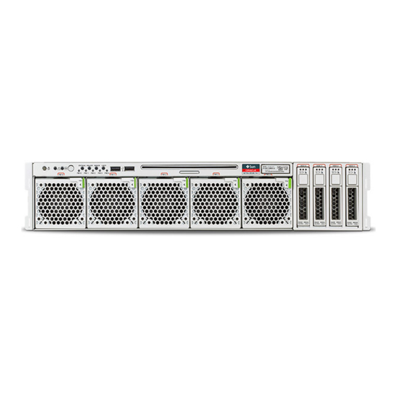
■ Server Overview The server is a carrier-grade, NEBS-certified, 2U server. The first illustration shows the server with the air filter. The second illustration shows the server without the air filter. Netra SPARC T4-1 Server Installation Guide • January 2013... - Page 11 Component Description One 8-core 64 thread 2.85 GHz SPARC T4 processor or one 4-core 32 threads 2.85 GHz SPARC T4 processor Memory 8 GB and 16 GB DDR3 DIMMs 16 DIMM slots, supporting a maximum of 256 GB Understanding the Server...
- Page 12 XAUI cards (fiber or copper versions) Related Information “Confirming Server and Site Specifications” on page 9 ■ “Installation Task Overview” on page 1 ■ “Front Panel Components” on page 5 ■ Netra SPARC T4-1 Server Installation Guide • January 2013...
-
Page 13: Front Panel Components
“Rear Panel Components” on page 6 ■ Front Panel Components Description Link Locator LED/Locator button: white Server Service, interpreting diagnostic LEDs Service Action Required LED: amber Server Service, interpreting diagnostic LEDs Main Power/OK LED: green Server Service, interpreting diagnostic LEDs Power button Alarm LEDs: Critical (red), Major (red), Server Service, interpreting diagnostic LEDs... -
Page 14: Rear Panel Components
Power supply status LEDs: Server Service, interpreting - OK (output): (green) diagnostic LEDs - Service Action Required: (amber) - AC or DC (input power): (green) Alarm port “Alarm Port” on page 68 Netra SPARC T4-1 Server Installation Guide • January 2013... - Page 15 Description Link Expansion slot 0 (PCIe 2.0 x8 or XAUI) “Optional Components” on page 23 Expansion slot 3 (PCIe 2.0 x8) “Optional Components” on page 23 Expansion slot 1 (PCIe 2.0 x8 or XAUI) “Optional Components” on page 23 Expansion slot 4 (PCIe 2.0 x8) “Optional Components”...
- Page 16 Netra SPARC T4-1 Server Installation Guide • January 2013...
-
Page 17: Confirming Server And Site Specifications
Confirming Server and Site Specifications These topics provide background information needed to install the server. “Physical Specifications” on page 9 ■ “Electrical Specifications” on page 10 ■ “Input Power Information” on page 11 ■ “Overcurrent Protection Requirements” on page 12 ■... -
Page 18: Electrical Specifications
Caution – The ports of this equipment or subassembly are suitable for connection to intra-building or unexposed wiring or cabling only. The intra-building port(s) of the equipment or subassembly must not be metallically connected to interfaces that Netra SPARC T4-1 Server Installation Guide • January 2013... -
Page 19: Input Power Information
connect to the outside plant wiring. These interfaces are designed for use as intra-building interfaces only (Type 2 or Type 4 ports as described in GR-1089-CORE, Issue 4) and require isolation from the exposed outside plant cabling. The addition of primary protectors is not sufficient protection in order to connect these interfaces metallically to outside plant wiring. -
Page 20: Overcurrent Protection Requirements
Note – Overcurrent protection devices must meet applicable national and local electrical safety codes, and be approved for the intended application. Netra SPARC T4-1 Server Installation Guide • January 2013... -
Page 21: Dc Power Source, Power Connection, And Grounding Requirements
Related Information “Electrical Specifications” on page 10 ■ “Input Power Information” on page 11 ■ “DC Power Source, Power Connection, and Grounding Requirements” on page 13 ■ “Physical Specifications” on page 9 ■ “Environmental Requirements” on page 14 ■ “Acoustic Noise Emissions” on page 15 ■... -
Page 22: Environmental Requirements
Caution – Netra rackmounted servers are certified to meet these worst-case operating conditions only when using an approved rackmount kit. You must strictly follow the rackmounting instructions in order to meet these environmental specifications. Netra SPARC T4-1 Server Installation Guide • January 2013... -
Page 23: Acoustic Noise Emissions
Specification Operating Nonoperating Ambient temperature Maximum: 5˚C to 45˚C (41˚F to 113˚F) up to –40˚C to 70˚C (–40˚F to 158˚F) † 1829 meters (6000 feet) Optimal: 21˚C to 23˚C (69.8˚F to 73.4˚F) Short term maximum: -5˚C to 55˚C (23˚F to 131˚F) Relative humidity 5% - 85% RH, non condensing, but not to exceed 93%, non condensing, 40˚C... -
Page 24: Airflow Clearance
(available open area) and assume a uniform distribution of the open area across the inlet and exhaust areas. Clearance values greater than these are recommended for improved cooling performance. Netra SPARC T4-1 Server Installation Guide • January 2013... - Page 25 Note – Be mindful that the combination of inlet and exhaust restrictions, such as cabinet doors and the spacing of the server from the doors, can affect the cooling performance of the server. Related Information “Physical Specifications” on page 9 ■...
- Page 26 Netra SPARC T4-1 Server Installation Guide • January 2013...
-
Page 27: Preparing For Installation
Preparing for Installation These topics provide background information needed to install the server. “Shipping Kit” on page 19 ■ “Handling Precautions” on page 21 ■ “ESD Precautions” on page 21 ■ “Tools Needed for Installation” on page 22 ■ Related Information “Confirming Server and Site Specifications”... - Page 28 Optional components (for example, PCIe cards) are packaged separately from the other items unless they are installed at the factory as part of the system. Related Information “Handling Precautions” on page 21 ■ “ESD Precautions” on page 21 ■ Netra SPARC T4-1 Server Installation Guide • January 2013...
-
Page 29: Handling Precautions
Handling Precautions Caution – Deploy the antitilt bar on the equipment rack before beginning an installation. Caution – The server weighs approximately 55 lb (25 kg). Two people are required to lift and mount this 2U server into a rack enclosure when using the procedures in this document. -
Page 30: Tools Needed For Installation
Terminal server ■ Patch panel connected to a terminal server ■ Related Information “Optional Components” on page 23 ■ “ESD Precautions” on page 21 ■ “Installing the Server” on page 23 ■ Netra SPARC T4-1 Server Installation Guide • January 2013... -
Page 31: Installing The Server
Installing the Server These topics describe how to install the server into an equipment rack using a rackmount kit. Note – In this guide, the term rack means either an open rack or a closed cabinet. “Optional Components” on page 23 ■... -
Page 32: Rack Cautions
Caution – Reliable Grounding. Maintain reliable grounding of rackmounted equipment. Give particular attention to supply connections other than direct connections to the branch circuit (for example, use of power strips). Netra SPARC T4-1 Server Installation Guide • January 2013... -
Page 33: Stabilize The Rack For Installation
“Rack Cautions” on page 24 ■ Documentation for your rack cabinet ■ Netra SPARC T4-1 Server Safety and Compliance Guide ■ Mounting the Server Into a 4-Post Rack These topics provide installation instructions for the 4-post rackmount kits. The server ships with a 19-inch, 4-post hardmount rackmount kit. You can order two optional rackmount kits for your specific 4-post rack. - Page 34 “Install the Server (600-mm, 4-Post Hardmount Rackmount Kit)” on page 38 Related Information “Preparing for Installation” on page 19 ■ “Rack Cautions” on page 24 ■ “Stabilize the Rack for Installation” on page 25 ■ Netra SPARC T4-1 Server Installation Guide • January 2013...
-
Page 35: 19-Inch, 4-Post Hardmount Rackmount Kit
19-Inch, 4-Post Hardmount Rackmount Kit Rear mount flanges (2) Rear mount support brackets (2) Bag of fasteners Hardmount brackets (2) Related Information “Install the Server (19-Inch, 4-Post Hardmount Rackmount Kit)” on page 28 ■ Installing the Server... -
Page 36: Install The Server (19-Inch, 4-Post Hardmount Rackmount Kit)
Use two to three of the supplied M4 x 0.5 x 5 mm panhead Phillips screws for each bracket, depending on the rack depth. Netra SPARC T4-1 Server Installation Guide • January 2013... - Page 37 5. Lift the server to the desired location in the rack. 6. Using two screws per side, secure the front of the hardmount brackets attached to the sides of the server to the front of the rack. 7. Get the two rear mount flanges from the rackmount kit. 8.
-
Page 38: 19-Inch, 4-Post Sliding Rail Rackmount Kit
After installing the server using this optional 19-inch, 4-post sliding rail rackmount kit, you can extend the server out of the rack for servicing. You also need the hardmount brackets from the standard rackmount kit that came with the server. Netra SPARC T4-1 Server Installation Guide • January 2013... - Page 39 Short brackets (2) Bag of fasteners Extension brackets (2) Telco slide assemblies (2) Threaded strips – M6 (4) 10-32 (4) Long brackets (2) Related Information “Install the Server (19-Inch, 4-Post Sliding Rail Rackmount Kit)” on page 32 ■ Installing the Server...
-
Page 40: Install The Server (19-Inch, 4-Post Sliding Rail Rackmount Kit)
These hardmount brackets and screws are shipped with the standard server ship kit, not as part of the sliding rail 19-inch, 4-post rackmount kit. 3. Press in the button on each slide assembly and pull the glide completely out of the slide. Netra SPARC T4-1 Server Installation Guide • January 2013... - Page 41 Glide Slide (in two parts) Button 4. Using eight of the M4 x 0.5 x 5 mm panhead Phillips screws from the rackmount kit (four for each side), screw each glide to the side of the server chassis. Installing the Server...
- Page 42 Use the M5 panhead screws from the inside. Use the M5 nuts, plain washers, and star washers from the outside. Use extension brackets instead of the long brackets if the dimension is greater than 665 mm. Netra SPARC T4-1 Server Installation Guide • January 2013...
- Page 43 Short bracket Slide Long bracket 9. Mount the slide on the other side of the rack. Repeat Step 7 Step 10. Push the slides completely into the assembly on each side of the rack and release the stop catches. 11. Align the glides attached to the server with the slide assemblies in the rack. You might find that there is too much or too little room between the two slides mounted in the rack.
- Page 44 The size of the screws varies, depending on your particular rack. Related Information “Stabilize the Rack for Installation” on page 25 ■ Netra SPARC T4-1 Server Installation Guide • January 2013...
-
Page 45: 600-Mm, 4-Post Hardmount Rackmount Kit
“19-Inch, 4-Post Sliding Rail Rackmount Kit” on page 30 ■ 600-mm, 4-Post Hardmount Rackmount Kit Adjustable rails (2) Side rails (2) Bag of fasteners Rear flanges (2) Related Information “Install the Server (600-mm, 4-Post Hardmount Rackmount Kit)” on page 38 ■... -
Page 46: Install The Server (600-Mm, 4-Post Hardmount Rackmount Kit)
3. Lift one of the adjustable rails to the desired location in the rack. Using two screws, secure the front of the rail in the rack. The size of the screws varies, depending on your particular rack. Netra SPARC T4-1 Server Installation Guide • January 2013... - Page 47 4. At the rear of the rack, use two screws to secure the rear of the adjustable rails to the rack. The size of the screws varies, depending on your particular rack. Installing the Server...
- Page 48 Do not completely secure the rear flanges to the adjustable rails. You will use these flanges to set the rack depth for the server in a later step. Netra SPARC T4-1 Server Installation Guide • January 2013...
- Page 49 8. Using eight of the M5 x 7 SEM screws (four for each side rail), secure the side rails to the sides of the server. The side rails can accommodate rack rail setbacks (the distance from the front of the rack to the rack rail) of 50 mm, 75 mm, or 100 mm, depending on the type of rack you are installing the server into.
- Page 50 9. Lift the server into the rack and slide the server onto the adjustable rails. Netra SPARC T4-1 Server Installation Guide • January 2013...
- Page 51 10. Push the server to the desired depth in the rack, then go to the rear of the server and push the rear flanges flush against the back of the server. If the rack is especially shallow, you can flip the rear flanges around so that they rest flush against the rear of the server.
- Page 52 15. At the front of the rack, use two screws per side to secure the side rails that are attached to the server to the front of the rack. The size of the screws varies, depending on your particular rack. Netra SPARC T4-1 Server Installation Guide • January 2013...
-
Page 53: Mounting The Server Into A 2-Post Rack
Related Information “Stabilize the Rack for Installation” on page 25 ■ “600-mm, 4-Post Hardmount Rackmount Kit” on page 37 ■ Mounting the Server Into a 2-Post Rack The server ships with a 19-inch, 4-post hardmount rackmount kit, but you can order optional rackmount kits for 2-post racks. - Page 54 “Install a Server (19-Inch, 2-Post Sliding Rail Rackmount Kit)” on page 59 Related Information “Mounting the Server Into a 4-Post Rack” on page 25 ■ “Preparing for Installation” on page 19 ■ Netra SPARC T4-1 Server Installation Guide • January 2013...
-
Page 55: 23-Inch, 2-Post Hardmount Rackmount Kit
23-Inch, 2-Post Hardmount Rackmount Kit Side brackets (2) Rear plates (2) Bag of fasteners Rail guides (2) Related Information “Install the Server (23-Inch, 2-Post Hardmount Rackmount Kit)” on page 47 ■ ▼ Install the Server (23-Inch, 2-Post Hardmount Rackmount Kit) Note –... - Page 56 3. Lift the rail guides to the desired height in the rack and, using two screws each, secure both rail guides to the rack. The size of the screws varies, depending on your particular rack. Netra SPARC T4-1 Server Installation Guide • January 2013...
- Page 57 4. Lift the server into the rack, and slide the server onto the rail guides. Installing the Server...
- Page 58 The position varies depending on the thickness of the rail in the rack. For example, the following figure shows where you would install the screw for the middle rack position on the rear plate. Netra SPARC T4-1 Server Installation Guide • January 2013...
- Page 59 b. Slide the rear plate in so that the screw slides into position into one of the eyelets. The screw head should be facing the rear of the server. The other side of the rear plate should be in front of the rack post. Installing the Server...
- Page 60 Secure the rear plate on the other post. Repeat Step a through Step Related Information “Stabilize the Rack for Installation” on page 25 ■ “23-Inch, 2-Post Hardmount Rackmount Kit” on page 47 ■ Netra SPARC T4-1 Server Installation Guide • January 2013...
-
Page 61: 19-Inch, 2-Post Hardmount Rackmount Kit
19-Inch, 2-Post Hardmount Rackmount Kit Rear plates (2) Bag of fasteners Side brackets (2) Related Information “Install the Server (19-Inch, 2-Post Hardmount Rackmount Kit)” on page 54 ■ Installing the Server... -
Page 62: Install The Server (19-Inch, 2-Post Hardmount Rackmount Kit)
3. Lift the server into the rack. 4. Using two screws for each bracket, secure the front of the server to the front of the rack. The size of the screws varies, depending on your rack. Netra SPARC T4-1 Server Installation Guide • January 2013... - Page 63 5. (Optional) If your environment contains especially high vibrations, install the rear plates to further secure the server to the rack. The rear plates attach to the rear of the post and to one of the three sets of eyelets on each side bracket, depending on the thickness of the post.
- Page 64 The screw heads should be facing the rear of the server. The other side of the rear plate should be in front of the rack post. c. Tighten the screws to secure the rear plate to the set of eyelets on the side bracket. Netra SPARC T4-1 Server Installation Guide • January 2013...
- Page 65 d. Using two screws, secure the other side of the rear plate to the back of the post. The size of the screws varies, depending on your rack. e. Secure the rear plate on the other post. Repeat Step a through Step Related Information...
-
Page 66: 19-Inch, 2-Post Rack Sliding Rail Rackmount Kit
Cable management arm Inside glides (2) Threaded strips – M6 (4) 10-32 (4) (not pictured) Bag of fasteners Related Information “Install a Server (19-Inch, 2-Post Sliding Rail Rackmount Kit)” on page 59 ■ Netra SPARC T4-1 Server Installation Guide • January 2013... -
Page 67: Install A Server (19-Inch, 2-Post Sliding Rail Rackmount Kit)
▼ Install a Server (19-Inch, 2-Post Sliding Rail Rackmount Kit) Note – The 19-inch, 2-post sliding rail rackmount kit supports rack web thicknesses (the width of the rack post) of 76.20 mm (3 in.), 101.6 mm (4 in.), and 127 mm (5 in.). Note –... - Page 68 To secure each bracket, use two of the M5 x 12.7 mm screws or two of the M6 x 13 mm screws. Tighten the screws enough to secure the brackets, but leave them loose enough for adjustment later. Netra SPARC T4-1 Server Installation Guide • January 2013...
- Page 69 5. Lift each rear bracket to the desired position at the rear of the rack and attach a rear bracket to each of the rear rack posts. To secure each bracket, use two of the M5 x 12.7 mm screws or two of the M6 x 13 mm screws, as you did in Step 4.
- Page 70 5), move the brackets inward or outward to the appropriate points, then tighten the brackets again. 7. Push in the slide buttons and slide the server all the way into the rack enclosure. Netra SPARC T4-1 Server Installation Guide • January 2013...
- Page 71 8. Fully tighten the screws on the front brackets. 9. Fully tighten the screws on the rear brackets. Installing the Server...
- Page 72 There are labels on both the rails and the CMA. The CMA side that has an arrow attaches to the right inner glide. The other side of the CMA attaches to the outer member. Netra SPARC T4-1 Server Installation Guide • January 2013...
- Page 73 11. Attach the CMA to the left rail. There are labels on both the rails and the CMA. The CMA side that has an arrow attaches to the left inner glide. The other side of the CMA attaches to the outer member.
- Page 74 Related Information “Stabilize the Rack for Installation” on page 25 ■ “19-Inch, 2-Post Rack Sliding Rail Rackmount Kit” on page 58 ■ Netra SPARC T4-1 Server Installation Guide • January 2013...
-
Page 75: Connecting Cables
Connecting Cables Perform the following tasks to connect and configure the network and serial ports before you attempt to boot the server. Step Description Links Review the cabling requirements. “Cabling Requirements” on page 67 Review the rear panel connectors and ports. “Identifying Ports”... -
Page 76: Identifying Ports
Telco dry alarm relay cable. In a telecommunications environment, use this port to connect to the central office alarming system. The alarm port relay contacts are rated for 100V, 0.2A maximum. Netra SPARC T4-1 Server Installation Guide • January 2013... - Page 77 Signal Description Signal Description RESET0+ ALARM1_NC RESET0- ALARM1_COM RESET1+ ALARM2_NO RESET1- ALARM2_NC ALARM0_NO ALARM2_COM ALARM0_NC ALARM3_NO ALARM0_COM ALARM3_COM ALARM1_NO CHASSIS FRAME GND Each alarm has a corresponding alarm LED on the front panel: ALARM0 and the Critical LED ■ ALARM1 and the Major LED ■...
-
Page 78: Ser Mgt Port
10/100BASE-T connection. If your network does not use a DHCP server, this port will not be available until you configure network settings through the SER MGT port. This port does not support connections to Gigabit networks. Netra SPARC T4-1 Server Installation Guide • January 2013... -
Page 79: Gigabit Ethernet Ports
Signal Description Signal Description Transmit Data + No Connect Transmit Data - Receive Data - Receive Data + No Connect No Connect No Connect Related Information “Rear Panel Components” on page 6 ■ “Connect the NET MGT Cable” on page 75 ■... -
Page 80: Usb Ports
Note – You can connect up to 126 devices to each of the four USB controllers (two ports in front, two ports in rear), for a total of 504 USB devices per server. Signal Description Signal Description +5V supply Data + Data - Ground Netra SPARC T4-1 Server Installation Guide • January 2013... -
Page 81: Video Port
Related Information “Rear Panel Components” on page 6 ■ “Front Panel Components” on page 5 ■ Video Port The server has one 15-pin VGA video port on the rear of the server. Use a HDB-15 video cable to connect to a video device. You can also use the supplied RJ-45 to DB-25 analog-to-digital video adapter to achieve the required connection. -
Page 82: Connecting Data And Management Cables
Connect a Category 5 (or better) cable from the SER MGT to a terminal device. When connecting a DB-9 cable, use the supplied RJ-45 to DB-9 crossover serial adapter to perform the crossovers given for each connector. Netra SPARC T4-1 Server Installation Guide • January 2013... -
Page 83: Connect The Net Mgt Cable
Related Information “SER MGT Port” on page 70 ■ “Connect the NET MGT Cable” on page 75 ■ “Connect Ethernet Network Cables” on page 76 ■ “Connect Other Data Cables” on page 77 ■ ▼ Connect the NET MGT Cable The service processor network management port is labeled NET MGT. -
Page 84: Connect Ethernet Network Cables
“Powering On the Server for the First Time” on page 79 ■ “Connect the SER MGT Cable” on page 74 ■ “Connect the NET MGT Cable” on page 75 ■ “Connect Other Data Cables” on page 77 ■ Netra SPARC T4-1 Server Installation Guide • January 2013... -
Page 85: Connect Other Data Cables
▼ Connect Other Data Cables If your server includes optional PCIe cards, connect the appropriate I/O cables to their connectors. ● If your server configuration includes optional PCIe cards, connect the appropriate I/O cables to their connectors. Refer to the PCIe card documentation for specific instructions. Related Information PCIe card documentation ■... - Page 86 Netra SPARC T4-1 Server Installation Guide • January 2013...
-
Page 87: Powering On The Server For The First Time
Powering On the Server for the First Time These topics include instructions for powering on the server for the first time, booting the server, and configuring the Oracle Solaris OS. Step Description Links Review requirements for the AC or DC power “Electrical Specifications”... -
Page 88: Assemble The Dc Power Cords
5. Locate the three wires coming from your DC power source that will be used in the connection to your unit. -48V or -60V (negative terminal) ■ Chassis ground ■ -48V or -60V Return (positive terminal) ■ Netra SPARC T4-1 Server Installation Guide • January 2013... - Page 89 Note – Depending on the DC power source, the -48V or -60V (negative terminal) might be marked with a minus (-) symbol. The -48V or -60V Return (positive terminal) might be marked with a positive (+) symbol. 6. Strip 1/2 in. (13 mm) of insulation from each of the wires coming from the DC power source.
- Page 90 12. Prepare the power cords. “Prepare the Power Cords” on page Related Information “Prepare the Power Cords” on page 83 ■ “Power On the Server for the First Time” on page 85 ■ Netra SPARC T4-1 Server Installation Guide • January 2013...
-
Page 91: Prepare The Power Cords
▼ Prepare the Power Cords Prepare the power cords by routing them from the power source to the server. Caution – Do not attach power cables to the power supplies until you first connect the server to a serial terminal or a terminal emulator (PC or workstation). Note –... -
Page 92: Connect A Terminal Or Emulator To The Ser Mgt Port
5. Continue with the installation by powering on the server for the first time. “Power On the Server for the First Time” on page Related Information “Connect the SER MGT Cable” on page 74 ■ Netra SPARC T4-1 Server Installation Guide • January 2013... -
Page 93: Power On The Server For The First Time
“SER MGT Port” on page 70 ■ “Rear Panel Components” on page 6 ■ “Power On the Server for the First Time” on page 85 ■ ▼ Power On the Server for the First Time 1. Confirm that you have installed the server in a rack and attached all of the data cables. - Page 94 Oracle Solaris OS is running. See “Oracle Solaris OS Configuration Parameters” on page 87 for a description of the Oracle Solaris OS parameters you must provide during initial configuration. Netra SPARC T4-1 Server Installation Guide • January 2013...
-
Page 95: Oracle Solaris Os Configuration Parameters
10. (Optional) Deploy the server for its intended use. Once the server has been configured and you have changed the default password, the server is ready for normal use. Related Information “Oracle Solaris OS Configuration Parameters” on page 87 ■ “Front Panel Components”... -
Page 96: Assign A Static Ip Address To The Sp
IP address to the SP. Note – For more information on configuring Oracle ILOM, refer to the Servers Administration and the Oracle ILOM documentation. Netra SPARC T4-1 Server Installation Guide • January 2013... - Page 97 1. Log in to the SP using a serial connection through the SER MGT port. For serial connection instructions, see “Connect a Terminal or Emulator to the SER MGT Port” on page 84. Log in to the SP as root (changeme is the default root password) to display the Oracle ILOM prompt.
- Page 98 8. (Optional) Verify that the parameters have been updated. -> show /SP/network -display properties /SP/network Properties: -> 9. Perform administrative tasks or service the Oracle’s Netra SPARC T4-1 server as needed. Refer to the Servers Administration and Server Service. Netra SPARC T4-1 Server Installation Guide • January 2013...
- Page 99 Related Information “Oracle Solaris OS Configuration Parameters” on page 87 ■ Oracle ILOM documentation ■ Servers Administration ■ Powering On the Server for the First Time...
- Page 100 Netra SPARC T4-1 Server Installation Guide • January 2013...
-
Page 101: Glossary
Glossary ANSI SIS American National Standards Institute Status Indicator Standard. Alert standard format (Netra products only). Automatic system recovery. American wire gauge. blade Generic term for server modules and storage modules. See server module storage module. Server module. See server module. - Page 102 The part of the server or server module with the CPU and other hardware that runs the Oracle Solaris OS and other applications. The term host is used to distinguish the primary computer from the SP. See SP. Netra SPARC T4-1 Server Installation Guide • January 2013...
- Page 103 ID PROM Chip that contains system information for the server or server module. Internet Protocol. Keyboard, video, mouse. Refers to using a switch to enable sharing of one keyboard, one display, and one mouse with more than one computer. Sound power level. Machine access code.
- Page 104 PCIe ExpressModule. Modular components that are based on the PCI Express industry-standard form factor and offer I/O features such as Gigabit Ethernet and Fibre Channel. POST Power-on self-test. Programmable read-only memory. PROM Predictive self healing. QSFP Quad small form-factor pluggable. Netra SPARC T4-1 Server Installation Guide • January 2013...
- Page 105 RAID expansion module. Sometimes referred to as an HBA See HBA. Supports the creation of RAID volumes on drives. Serial attached SCSI. System configuration chip. Serial management port. A serial port on the server SP, the server module SP, SER MGT and the CMM.
- Page 106 User interface. Underwriters Laboratory Inc. U.S. NEC United States National Electrical Code. Coordinated Universal Time. Universal unique identifier. UUID World wide name. A unique number that identifies a SAS target. Netra SPARC T4-1 Server Installation Guide • January 2013...
-
Page 107: Index
Index Numerics 19-inch, 2-post hardmount cables installing, 54 adapters for serial data cables, 74 rackmount kit, 53 cage clamp tool, 82 19-inch, 2-post slide mount configuration information needed, 67 installing, 59 current specifications, 10 rackmount kit, 58 19-inch, 4-post hardmount installing, 28 DC input plug, 80 rackmount kit, 27... - Page 108 84 show /SP/network command, 90 physical specifications, 9 show command, 90 pinouts SP OK/Fault LED, 86 alarm connector, 68 specifications Ethernet connectors, 71 electrical, 10 NET MGT connector, 70 Netra SPARC T4-1 Server Installation Guide • January 2013...
- Page 109 physical, 9 start command, 86 stop bit, 84 surge protector, 11 task overview, installation, 1 tools for installation, 22 USB ports pinouts, 72 video port pinouts, 73 voltage, 10 Index...
- Page 110 Netra SPARC T4-1 Server Installation Guide • January 2013...
Need help?
Do you have a question about the NETRA SPARC T4-1 and is the answer not in the manual?
Questions and answers