
Related Manuals for Konica Minolta DRYPRO Model 793


Summary of Contents for Konica Minolta DRYPRO Model 793
-
Page 1: Laser Imager
LASER IMAGER DRYPRO MODEL 793 OPERATION MANUAL CODE NO. 0792 (UL), 0791 (CE) No. 26-2, Nishishinjuku 1-chome, Shinjuku-ku, Tokyo 163-0512, Japan... -
Page 2: Table Of Contents
Table of Contents Foreword.............. Ch.5 Web Maintenance Mode ......99 5-1 Overview of Web Maintenance Mode....100 About This Manual ..........5-2 Startup/Shutdown of Web Maintenance Mode ... 103 5-3 Menu Items of Web Maintenance Mode ..... 107 Ch.1 Safety Precautions & Warnings ....5-3-1 STATUS........... -
Page 3: Foreword
We would like to thank you for purchasing Laser Imager DRYPRO Vstage MODEL 793 (hereinafter referred to as DRYPRO 793). DRYPRO MODEL 793 is a laser imager which realized a complete dry process, devel- oped by considering the environment and operability, while maintaining high perfor- mance and high image quality. -
Page 4: Operation Environment
Foreword Features DRYPRO MODEL 793 is a laser imager which realized a complete dry process, developed by consid- ering the environment and operability, while maintaining high performance and high image quality. High-quality Image 1) Realizing super-sharpened images with the pixel size of 43.75 µm and 25µm as well as capability of mammography. -
Page 5: About This Manual
About This Manual Be sure to read this chapter before using this manual so that the manual can be fully utilized. < 3 > DRYPRO Vstage MODEL 793 Operation Manual Ver.1.01 2005.1... - Page 6 About This Manual How to use this manual Structure of this manual This manual consists of the chapters listed below. Chapter1 Safety Precautions & Warnings When using the DRYPRO 793, the cautions detailed in this chap- ter must be strictly followed in order to safely use the device. Chapter2 Product Outline The product outline of DRYPRO 793 is described in this chapter.
-
Page 7: Page Layout
About This Manual Page Layout Ch.3 Operation Title This title stands for the 3-4 Film Loading general meanings for When the supply tray becomes empty, a beep sound is released, followed by the [Film Set] button that is newly displayed in the message column of the Operation Panel. - Page 8 About This Manual < 6 > DRYPRO Vstage MODEL 793 Operation Manual Ver.1.01 2005.1...
-
Page 9: Ch.1 Safety Precautions & Warnings
Chap. Safety Precautions & When using the DRYPRO 793, the cautions Warnings detailed in this chapter must be strictly followed in order to safely use the device. < 7 > DRYPRO Vstage MODEL 793 Operation Manual Ver.1.01 2005.1... - Page 10 Ch.1 Safety Precautions & Warnings Alert and Symbol Marks Safety Alert Symbol This is the safety alert symbol and is intended to draw the attention of the user to potential dangers to the user him/herself or to others that may arise during the use or operation of this system. These messages must be read thoroughly and strictly observed.
-
Page 11: Warning Labels
Ch.1 Safety Precautions & Warnings Warning Labels Warning labels on the DRYPRO 793 are affixed at the locations shown below, and indicate the possible dan- ger to the user. p.12 Locations of Description of Warning Labels Warning Labels (1) Laser Caution Label (4) Class1 Laser Product Label (3) High Temp. - Page 12 Ch.1 Safety Precautions & Warnings (6) Jam Release Label-B•C (7) Film Loading Label (8) Deodorant Filter Change Label NOTE : If the contents of this page are not legible, order a new manual. < 10 > DRYPRO Vstage MODEL 793 Operation Manual Ver.1.01 2005.1...
- Page 13 Ch.1 Safety Precautions & Warnings (9) Cleaning Roller Cleaning Label NOTE : If the contents of this page are not legible, order a new manual. < 11 > DRYPRO Vstage MODEL 793 Operation Manual Ver.1.01 2005.1...
- Page 14 Ch.1 Safety Precautions & Warnings Locations of Warning Labels Description of Warning Labels Internal (8) Deodorant Filter Change Label (1) Laser Caution Label (5) Jam Release Label (6) Jam Release Label B¥C (7) Film Loading Label Rear • Left Side (1) Laser Caution Label (4) Class1 Laser Product Label Deodorant Filter Case...
-
Page 15: Cautions For Installation
Ch.1 Safety Precautions & Warnings Cautions for Safety Thoroughly read the Cautions for Safety before use, and use the device correctly. Strictly observe all cau- tions detailed here because they are quite important to secure the safe use of the device. Cautions for Installation WARNING •... - Page 16 Ch.1 Safety Precautions & Warnings Cautions for Usage WARNING • Never open or close any covers other than the specified in this Operation Manual. High voltage may be applied on some units in the device. If you touch them accidentally, you may suffer burns or an electric shock.
- Page 17 Ch.1 Safety Precautions & Warnings CAUTION • As for any servicing other than "Servicing by User" described in this Operation Manual, contact a ser- vice person as they require an expert technology. If you perform any service other than "Servicing by User" by yourself, and there are any problems on it, this may cause an electric shock or fire.
- Page 18 Ch.1 Safety Precautions & Warnings < 16 > DRYPRO Vstage MODEL 793 Operation Manual Ver.1.01 2005.1...
-
Page 19: Ch.2 Product Outline
Chap. Product Outline Product outline of the DRYPRO 793 is detailed in this chapter. < 17 > DRYPRO Vstage MODEL 793 Operation Manual Ver.1.01 2005.1... -
Page 20: Name Of Each Component
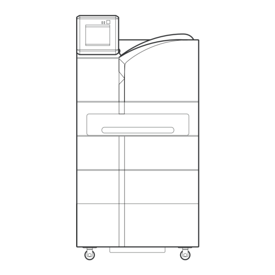
Ch.2 Product Outline 2-1 Name of Each Component Each component and its function of the DRYPRO 793 is detailed below. 2-1-1 Front and Left Side View 1) Front Upper Cover 4) Exit Cover Film size for the 2) Supply Tray 1 DRYPRO 793 can be selected from 14"x17", 14"x14", 11"x14",... - Page 21 Ch.2 Product Outline 2-1-2 Operation Panel 1) Operation Button 2) Operation Lamp 4) Operation Panel 3) Timer Lamp 1) Operation Button 3) Timer Lamp (green) Start up or shut down the DRYPRO Lights when the Start Timer is ON. 793. 4) Operation Panel 2) Operation Lamp(blue/orange) Operates and performs various settings...
- Page 22 Ch.2 Product Outline 2-1-3 Rear, Right Side, Top View 1) Film Exit Tray 7) Outlet 2) Front Upper Cover Release Lever 3) Right Cover 8) Inlet 9) Ethernet Port 4) Power Breaker 10) Serial Port 5) Power Cable Connector 6) Power Cable 1) Film Exit Tray 6) Power Cable Printed films are output to this tray.
- Page 23 Ch.2 Product Outline LEDs at the Ethernet Port. Two LEDs at the Ethernet Port indicate the following. Lower right of the rear Link / Activity LED Com. Speed LED - Link/Activity LED (upper) Com. Status Link Lights in orange Activity Lights in green - Com.
- Page 24 Ch.2 Product Outline 2-1-4 Main Unit without Outer Covers 1) Lever-A 7) Deodorant Filter Case Housing (yellow) 6) Deodorant Filter p.128 Resolving the Film Jam 2) Lever-B 4) Cover-B 5) Cover-C 3) Lever-C Be careful not to touch 1) Lever-A (green) 5) Cover-C the Deodorant filter Locks the Deodorant Filter Case.
- Page 25 Ch.2 Product Outline 2-1-5 Options 1. Supply 2, 3 Tray 1) Supply 2 Tray 1) Supply 3 Tray 1) Supply 2, 3 Tray (2nd, 3rd tray) Load the film. 2. Lis-793 1) Lis-793 2) Sorter Cover 1) Lis-793 2) Sorter Cover Printed films are output to five bins of When a film jam occurs in the Sorter the sorter and to the Film Exit Tray...
- Page 26 Ch.2 Product Outline 2-1-6 Supply Tray & Cutter Do not place anything 1) Shutter or lean on the Supply Tray when it is pulled 2) Holding Plate out from the DRYPRO 793. It may cause dam- age to the device. 6) Side Stoppers 3) Winding Shaft 5) Cutter...
-
Page 27: Internal Structure
Ch.2 Product Outline 2-2 Internal Structure Internal structure of the DRYPRO 793 is outlined below. A film is transported from 1) through 7) in sequence in print process. 11) Lis-793 10) Operation Panel 8) Deodorant Filter 6) H-PRO Unit 7) Cooling/Discharge Unit 1) Supply Unit 5) Elevator Transport... - Page 28 Ch.2 Product Outline < 26 > DRYPRO Vstage MODEL 793 Operation Manual Ver.1.01 2005.1...
- Page 29 Chap. Operation How to operate the DRYPRO 793 is detailed in this chapter. < 27 > DRYPRO Vstage MODEL 793 Operation Manual Ver.1.01 2005.1...
-
Page 30: Ch.3 Operation
Ch.3 Operation 3-1 Operation Panel The operation, control and settings of this device can be made by using the control panel located on the main unit. The following shows the operating procedures. 1) Message Column 3) Job Info. 2) Loaded Film Info. 4) Status Info. - Page 31 Ch.3 Operation Status Info : Displays the current status of the DRYPRO 793. When Lis-793 or Supply 3 Tray is equipped on the main unit, each illustration will be displayed, and the cover position is displayed when it is open. [Start Timer] Button : Touch this button to set the start timer.
-
Page 32: Startup
Ch.3 Operation 3-2 Startup How to start up the DRYPRO 793 is detailed below. Turn ON the power breaker located on the right side of the DRYPRO 793. Press and hold the [Operation] button on the Control Panel for approx. 1 sec. Pressing the [Operation] button again will shut down the power. -
Page 33: Shutdown
Ch.3 Operation 3-3 Shutdown How to shut down the DRYPRO 793 is detailed below. p.31 Shutdown without using There are two ways for shutting down the DRYPRO 793 as shown below. the start 1. Shutdown using the start timer for the next startup. timer This is the shutdown procedure to automatically start up the device next time. - Page 34 Ch.3 Operation Touch the [OK] button. - Saves the selected day & time for the next startup, and enters the sleep mode. - Touching the [RETURN] button will cancel the start timer setup, and returns to the print ready status. Each fan continues operation in order to cool inside of the unit...
- Page 35 Ch.3 Operation Cancelling the sleep mode How to manually cancel the sleep mode without waiting the start up set by the timer is detailed below. Touch the Operation Panel in the status shown in the left. - A message to confirm the cancellation of the sleep mode will be displayed.
- Page 36 Ch.3 Operation 2. Shutdown without using the start timer How to manually start up the DRYPRO 793 without using the start timer is detailed below. Confirm that "Printing" is not displayed on the Operation Panel. The power can be turned OFF even when the DRYPRO 793 is in printing operation or in the status that the print job is registered.
-
Page 37: Film Loading
Ch.3 Operation 3-4 Film Loading When the supply tray becomes empty, a beep sound is released, followed by the [Film Set] button that is newly displayed in the message column of the Operation Panel. (Beep sound can be selected from "Silent", "Single" and "Continuous" at the time of installation) When this button is displayed, follow the procedures shown below to load the film package in the supply tray. - Page 38 Ch.3 Operation Remove the Sandwich Paper left in the Supply Tray. Lift the Pressure Plate, and pulled out the Film Dispose of the Film Package that has been wounded up by the Package after removing winding shaft. the sandwich cardboard according to the regula- tions of the local gov- ernment.
- Page 39 Ch.3 Operation Remove the seal, and open the front and back edges of the package. Touch the [NEXT] button on the Operation Panel. - An animation showing how to load the film package (shutter close ~ cutting the light-proof package) will be displayed.
- Page 40 Ch.3 Operation Touch the [NEXT] button. - An animation showing how to load the film package Animation of shutter (returning the Cutter ~ closing the tray) will be dis- close ~ cutting light- played. proof bag. Put the Cutter back in the Cutter Pocket. (3 in the left fig.) Push the Supply Tray back until it is locked.
- Page 41 Ch.3 Operation Reaction to the case that the [Film Set] button does not dissapear despite the film is loaded. - When the Supply Tray was pushed back into the Main Unit and locked without cut- ting the front edge of the film package, the [Film Set] button will be displayed again. ("0"...
-
Page 42: Sleep Mode
Ch.3 Operation 3-5 Sleep Mode The DRYPRO 793 incorporates a Sleep Mode. Sleep Mode is the mode that allows the device automatically switches to power-save mode when an input on the Operation Panel or print operation has not been conducted for a specific time while the device is in "READY" status. 1. - Page 43 Ch.3 Operation Cancelling the Sleep Mode (Sleep Mode for the HPRO Drum) How to cancel the Sleep Mode for the HPRO Drum and restore the READY status is detailed below. Touch the [CANCEL] button. - Temperature of the HPRO Drum increases through warming up, and restores the READY status.
-
Page 44: Changing The Film Size And Film Type
Ch.3 Operation 3-6 Changing the Film Size and Film Type It is not necessary to change these in normal operation, however, for the case where it become necessary depending on the alteration of the work flow, etc., how to change the film size or type that is printed on the DRYPRO 793 is detailed below. - Page 45 Ch.3 Operation Following procedures can be skipped when only the film type should be changed and the film size should no be changed. Load the film package likewise the procedure for "3.4 Film Loading". p.35 FILM LOADING Do not put anything or lean on the Supply Tray while it is pulled out. Doing so will damage the Supply Tray.
- Page 46 Ch.3 Operation Remove two long screws that secure the side 11x14 14x14 14x17 stoppers at the original position. Remove two short screws that are located in the front and back of the Supply Tray, the new posi- tions to which the size should be changed. Do not remove these two Using the two long screws removed in the step...
- Page 47 Ch.3 Operation Follow the step 8 onward of the "Film Loading", and load the film package. p.35 Film Loading Whenever the film size or film type is changed, make sure to process an exposed film (dummy) before processing the film for actual diagnosis, and check that problems such as following are not observed.
- Page 48 Ch.3 Operation < 46 > DRYPRO Vstage MODEL 793 Operation Manual Ver.1.01 2005.1...
-
Page 49: Ch.4 Maintenance Mode
Chap. Maintenance Mode How to operate the Maintenance Mode of the DRYPRO 793 is detailed in this chapter. < 47 > DRYPRO Vstage MODEL 793 Operation Manual Ver.1.01 2005.1... -
Page 50: Maintenance Mode Overview
Ch.4 Maintenance Mode 4-1 Maintenance Mode Overview The DRYPRO 793 incorporates two different modes, one is the Menu Mode with which various setups can be viewed, the other is the Maintenance Mode with which various maintenance operation can be performed. Menu Mode : A mode which allows the user, under the print-ready status (online) to check various setups made on the DRYPRO 793. - Page 51 Ch.4 Maintenance Mode 4-1-3 List of Maintenance Mode Functions Following is the list of items that can be selected or practiced by each user level. (✕ : not displayed, ▲ : display only ❍ : can be altered) MENU ITEM USER LEVEL DESCRIPTION ▲...
-
Page 52: Switching To The Menu Mode
Ch.4 Maintenance Mode 4-2 Switching to the Menu Mode How to switch to the Menu Mode is detailed below. 4-2-1 Switching to and Operating the Menu Mode How to switch to the Menu Mode and its operation are detailed below. Touch the [Menu] button. - Page 53 Ch.4 Maintenance Mode 4-2-2 Switching the Menu Mode to the Normal Screen How to switch the Menu Mode to the Normal screen is detailed below. Touch the [RETURN] button. - Returns to the normal screen. < 51 > DRYPRO Vstage MODEL 793 Operation Manual Ver.1.01 2005.1...
-
Page 54: Switching To The Maintenance Mode
Ch.4 Maintenance Mode 4-3 Switching to the Maintenance Mode How to switch to the Maintenance Mode is detailed below. 4-3-1 Switching to the Maintenance Mode (using the user level) How to switch to the Maintenance Mode is detailed below. p.50 Switching to Switch to the Menu Mode. - Page 55 Ch.4 Maintenance Mode Touch the [OK] button. - "Maintenance Mode" screen will be displayed when the input password is correct. - A message indicating that the password is wrong if the input password is not correct. Input the correct pass- word.
- Page 56 Ch.4 Maintenance Mode 4-3-2 Switching to the Maintenance Mode (without using the user level classification) How to switch to and operate the Maintenance Mode is detailed below. p.50 Switching to Switch to the Menu Mode. the Menu - "MENU MODE" screen will be displayed. Mode Touch the [Maintenance] button.
- Page 57 Ch.4 Maintenance Mode 4-3-3 Switching to the Normal screen from the Maintenance Mode How to switch the Maintenance Mode to the Normal screen is detailed below. Touch the [RETURN] button. - Returns to the Normal screen. < 55 > DRYPRO Vstage MODEL 793 Operation Manual Ver.1.01 2005.1...
-
Page 58: Operation Of Each Menu
Ch.4 Maintenance Mode 4-4 Operation of Each Menu Items that can be set in the Maintenance Mode are detailed below. 4-4-1 PRINT QUEUE INFO <PRINT SETUP> User Level Status of the print job and its info can be checked using this item. Maximum 5 jobs (15 ●... -
Page 59: Previous Print
Ch.4 Maintenance Mode 4-4-2 PREVIOUS PRINT <PRINT SETUP> User Level The DRYPRO 793 stores in the HDD, the print data that has been already printed. This allows reprint of the data previously printed. How to reprint the data is detailed below. ●... - Page 60 Ch.4 Maintenance Mode Touch the [PRINT] button. - Registers the print job for previous print, and returns to the "Maintenance Mode (PRINT SETUP)" screen. - Touching the [NO] button returns to the "Maintenance Mode (PRINT SETUP)" screen without previous print- ing.
- Page 61 Ch.4 Maintenance Mode Touch the [OK] button. - Returns to the "PREVIOUS PRINT" screen. - No. on the [Numeric] button of the "Page Search" column will change to that input in the step 3. - Touching the [CANCEL] button returns to the "Reprint Data Select"...
- Page 62 Ch.4 Maintenance Mode Input the copy count with which the prints are made. INPUT VALUE Buttons displayed on the screen with which numericals are input have following meanings. [<] key : Cursor moves to the left by one space. [>] key : Cursor moves to right by one space.
-
Page 63: Queue Clear
Ch.4 Maintenance Mode 4-4-3 QUEUE CLEAR <PRINT SETUP> User Level Deletes the print data stored in the print job file on the DRYPRO 793. Print data can be deleted per diagnostic device from which the data was sent. ● Disp How to delete the print data in the print job file is detailed below. -
Page 64: Test Print
Ch.4 Maintenance Mode 4-4-4 TEST PRINT <PRINT SETUP> User Level Prints an internal SMPTE pattern that is used for density calibration. How to print the SMPTE pattern is detailed below. ● ● ● Disp ● ● ● p.52 Switching to Switch to the Maintenance Mode. - Page 65 Ch.4 Maintenance Mode Touch the [PRINT] button. - Displays a confirmation message for test print. Touch the [YES] button. - Registers the print job for SMPTE pattern, and returns to the "Maintenance Mode (PRINT SETUP)" screen. - Touching the [NO] button will return to the "Mainte- nance Mode (PRINT SETUP)"...
-
Page 66: Calibration
Ch.4 Maintenance Mode 4-4-5 CALIBRATION <PRINT SETUP> User Level Allows to calibrate and correct the density of the printed film. ● ● ● Disp The DRYPRO793 incorporates a densitometer in the Cooling/Discharge section, which enables to per- ● ● ● form an automatic density control of the image every time when a new film package is loaded. - Page 67 Ch.4 Maintenance Mode Touch the [YES] button. - Registers the print job for the calibration sheet, and returns to the "Maintenance Mode (PRINT SETUP)" screen. - Touching the [RETURN] button will return to the "Main- tenance Mode (PRINT SETUP)" screen without print- ing the calibration sheet.
-
Page 68: Mammo Qc Print
Ch.4 Maintenance Mode 4-4-6 MAMMO QC PRINT <PRINT SETUP> User Level Allows to print a Mammo QC pattern that is incorporated in the DRYPRO 793, and to be used for den- ● ● ● Disp sity control of the mammographic images. ●... - Page 69 Ch.4 Maintenance Mode Touch the [PRINT] button. - Registers the print job for Mammo QC pattern, and returns to the "Maintenance Mode (PRINT SETUP)" screen. - Touching the [NO] button will return to the "Mainte- nance Mode (PRINT SETUP)" screen without printing the Mammo QC pattern.
-
Page 70: Print Condition
Ch.4 Maintenance Mode 4-4-7 PRINT CONDITION <PRINT SETUP> User Level Allows to assign a default print condition to each diagnostic device for the case that the print condi- ● ● ● Disp tion is not designated by the diagnostic device. ●... - Page 71 Ch.4 Maintenance Mode p.52 Switching to Switch to the Maintenance Mode. the Mainte- nance Mode Touch the [PRINT SETUP] button of the "Main- tenance" screen. Touch the [PRINT CONDITION] button. - "CH SELECT" screen will be displayed. - Touching the [RETURN] button will cancel the Mainte- nance Mode, and return to the Normal screen.
- Page 72 Ch.4 Maintenance Mode Touch the arrow buttons [t], [s] to select the the Smoothing to be applied. - Touch the left arrow [t] button to decrement the value by one, and to decrease the smoothing of the image. - Touch the right [s] button to increment the value by one, and to increase the smoothing of the image.
- Page 73 Ch.4 Maintenance Mode Touch the [OK] button. - Returns to the "Print Condition" screen. - The display on the button in "Max. Den" column changes to the value input in the step 3. - Touching the [CANCEL] button will return to the "Print Condition"...
- Page 74 Ch.4 Maintenance Mode Touch the arrow buttons [t], [s] to select the the polarity to be applied. - Touch either of the arrow [t], [s] buttons to switch between the "Neg" and "Pos". Touch the arrow buttons [t], [s] to select the the border to be applied.
-
Page 75: Lut Setup
Ch.4 Maintenance Mode 4-4-8 LUT SETUP <PRINT SETUP> User Level The DRYPRO 793 incorporates a library of LUTs that we recommends for various diag- nostic devices. Selecting the LUT from this library, and applying it to each channel in ● ●... - Page 76 Ch.4 Maintenance Mode Touch the arrow buttons [t], [s] to select the connected diagnostic device. - Touch either of the arrow [t], [s] buttons to switch among the diagnostic devices. - "LUT Library" screen also changes upon the change of the diagnostic device.
- Page 77 Ch.4 Maintenance Mode Input the value for the selected point. - Input the value in the range of "0" to the max. density set in the "Print Condition". Touch the [OK] button. - Returns to the "LUT Setup" screen. INPUT VALUE Buttons displayed on the screen with which numericals are input have following meanings.
- Page 78 Ch.4 Maintenance Mode List of LUT Library LUTs listed in the library that is incorporated in the DRYPRO 793 at the factory is shown below. LUT Name Modality Film Description CT&MR_KC_B LUT of our recommendation for blue base film on CT/MR. CT&MR_LOW_B Blue LUT with slightly lower density setting than CT&MR_KC_B.
- Page 79 Ch.4 Maintenance Mode Differences among "KC", "LOW", "HIGH", "LINEAR" of each LUT are illustrated as below. HIGH KC LINEAR < 77 > DRYPRO Vstage MODEL 793 Operation Manual Ver.1.01 2005.1...
-
Page 80: Film Data
Ch.4 Maintenance Mode 4-4-9 FILM DATA <TRAY SETUP> User Level Allows to view the collected data of processed films. Data classified in film size, film type or channel, ● ● ● Disp and collected by day, week or month can be viewed. p.52 Switching to Switch to the Maintenance Mode. - Page 81 Ch.4 Maintenance Mode - Selecting "DAILY" displays the film data per day over 8 days on a page. - Selecting "WEEKLY" displays the film data per day over 5 weeks on a page. - Selecting "MONTHLY" displays the film data per month over 3 months on a page. - Film data collected "DAILY"...
-
Page 82: Film Setup
Ch.4 Maintenance Mode 4-4-10 FILM SETUP <TRAY SETUP> User Level Allows to set the film size and film type that are used on the DRYPRO 793. Setup items are as follows. ● ● ● Disp ● Three Supply Trays, that are 8"x10" exclusive, 10"x12" exclusive and 14" exclusive p.42 Changing the (11"x14"/ 14"x14"/ 14"x17") are available. - Page 83 Ch.4 Maintenance Mode Touch the [SAVE] button. - Returns to the "Maintenance Mode (TRAY SETUP)" screen after saving the settings. < 81 > DRYPRO Vstage MODEL 793 Operation Manual Ver.1.01 2005.1...
-
Page 84: Start Timer
Ch.4 Maintenance Mode 4-4-11 START TIMER <TIMER SETUP> User Level How to set the Start Timer is detailed below. Startup time can be set for each day of the week using the Start Timer function. ● ● ● Disp ● p.31 Shutdown using the Switch to the Maintenance Mode. - Page 85 Ch.4 Maintenance Mode When all days are set to "OFF" in the "STAT TIMER" screen, [START TIMER] button will not be displayed on the Normal screen. < 83 > DRYPRO Vstage MODEL 793 Operation Manual Ver.1.01 2005.1...
-
Page 86: Time Set
Ch.4 Maintenance Mode 4-4-12 TIME SET <TIMER SETUP> User Level Allows to set the current time (year, month, day, hour, minute) of the internal clock. ● ● ● Disp ● p.51 Shutdown using the Switch to the Maintenance Mode. Start Timer p.52 Switching to the Mainte- Touch the [TIMER SETUP] button on the "Main-... - Page 87 Ch.4 Maintenance Mode Touch the arrow buttons [t], [s] to select the the "HOUR". - Touching the right arrow [t] decrements the value by one. - Touching the right arrow [s] increments the value by one. - "HOUR" can be set in the range of "AM1" through "PM12".
-
Page 88: Touch Panel
Ch.4 Maintenance Mode 4-4-13 TOUCH PANEL <OTHER SETUP> User Level Allows to set up the Touch Panel of the DRYPRO 793. ● ● ● Disp ● p.52 Switching to Switch to the Maintenance Mode. the Mainte- nance Mode Touch the [OTHER SETUP] button on the "Maintenance"... - Page 89 Ch.4 Maintenance Mode Touch the [SAVE] button. - Returns to the "Maintenance Mode (Other Setup)" screen after saving the settings. < 87 > DRYPRO Vstage MODEL 793 Operation Manual Ver.1.01 2005.1...
-
Page 90: Sleep Mode
Ch.4 Maintenance Mode 4-4-14 SLEEP MODE <OTHER SETUP> User Level Allows to set the Sleep Mode of the DRYPRO 793. Two modes are available, one for the Operation Panel, and the other for HPRO Drum. ● ● ● Disp How to activate the mode and to set the interval before the mode starts are detailed ●... - Page 91 Ch.4 Maintenance Mode INPUT VALUE Buttons displayed on the screen with which numericals are input have following meanings. [<] key : Cursor moves to the left by one space. [>] key : Cursor moves to right by one space. [BS] key : Delete one character in the adjacent left of the cursor.
-
Page 92: Sorter Setup
Ch.4 Maintenance Mode 4-4-15 SORTER SETUP <OTHER SETUP> User Level Allows to set the Lis-793, an optional sorter for the DRYPRO 793. Assigns the order of film delivery to each sorter when the sorter is in use. ● ● ● Disp ●... - Page 93 Ch.4 Maintenance Mode Touch the arrow [t], [s] buttons to select the "TEST PRINT BIN". - Touching the arrow [t], [s] buttons will switch between "TOP" and "BOTTOM". The test print for which the bin is specified in "Test Print Bin" means "SMPTE Pattern (including mammo)"...
- Page 94 Ch.4 Maintenance Mode When an illegal setting is made on the "Sorter Setup" screen, a message in the right will appear when the [SAVE] button is pressed. Touch the [OK] button to return to the "Sorter Setup" screen, and make a correct setup. <...
-
Page 95: Front Cover Open
Ch.4 Maintenance Mode 4-4-16 FRONT COVER OPEN <OTHER SETUP> User Level Use this procedure when the front lower cover needs to be opened due to the reason other than a film jam. ● Disp ● p.52 Switching to Switch to the Maintenance Mode. the Mainte- nance Mode Touch the [OTHER SETUP] button on the... -
Page 96: System Reset
Ch.4 Maintenance Mode 4-4-17 SYSTEM RESET <OTHER SETUP> User Level Allows to initiate a cold start of the DRYPRO 793. ● Disp ● When the DRYPRO 793 is restarted by the "System Reset", all print data including the unprinted data in the job file and the data printed and stored in the device will be deleted. p.52 Switching to Switch to the Maintenance Mode. -
Page 97: Dust Cleaning
Ch.4 Maintenance Mode 4-4-18 DUST CLEANING <OTHER SETUP> User Level In normal condition, [DUST CLEANING] button will be displayed every time when the DRYPRO 793 reaches 2,000 prints, and touching this button allows to initiate the cleaning ● Disp of cleaning rollers. However, when the printed image shows deterioration in comparison to ●... - Page 98 Ch.4 Maintenance Mode Insert the cleaning sheet parallel to the roller surface between the Cleaning Roller and the Facing Roller. (4 in the left fig) As shown in the fig, move the Lever up and down while holding the top edge of the cleaning sheet with a hand.
- Page 99 Ch.4 Maintenance Mode Close the Left Cover. Close the front lower cover. When disposing of the cleaning sheet after use, please follow the regulations and ordinance of the local government. < 97 > DRYPRO Vstage MODEL 793 Operation Manual Ver.1.01 2005.1...
- Page 100 Ch.4 Maintenance Mode < 98 > DRYPRO Vstage MODEL 793 Operation Manual Ver.1.01 2005.1...
-
Page 101: Ch.5 Web Maintenance Mode
Chap. How to operate the WEB Maintenance Mode that Maintenance enables a remote maintenance of the DRYPRO Mode 793 using a separate PC is detailed in this chap- ter. < 99 > DRYPRO Vstage MODEL 793 Operation Manual Ver.1.01 2005.1... -
Page 102: Overview Of Web Maintenance Mode
Ch.5 Web Maintenance Mode 5-1 Overview of Web Maintenance Mode DRYPRO 793 incorporates the ability of Web Maintenance when it is connected to the PC through Ethernet. Using the Web Maintenance Mode, settings on the DRYPRO 793 can be browsed and changed from the remote site. Web Maintenance Mode can be operated from the Internet Explore using a PC that satisfies the following require- ments. - Page 103 Ch.5 Web Maintenance Mode 5-1-1 User Level of the Web Maintenance Mode Alike the Maintenance Mode operated from the Operation Panel of the DRYPRO 793, authority level of the users who perform the Web Maintenance can be set. This user level is classified into three levels, and the scope of functions that can be operated by each user level is defined.
- Page 104 Ch.5 Web Maintenance Mode 5-1-2 Menu of Web Maintenance Mode Web Maintenance Mode is comprised of the following five means. Similar operation as that made from the Operation Panel of the DRYPRO 793 in the Maintenance Mode can be practiced also for the Web Maintenance Mode. However, "TEST PRINT (PRINT SETUP)", "CALIBRATION (PRINT SETUP)", "MAMMO QC PRINT (PRINT SETUP)", "TOUCH PANEL (OTHER SETUP)", "FRONT COVER OPEN (OTHER SETUP)"...
-
Page 105: Startup/Shutdown Of Web Maintenance Mode
Ch.5 Web Maintenance Mode 5-2 Startup/Shutdown of Web Maintenance Mode How to start up or shut down the Web Maintenance Mode is detailed below. 5-2-1 Startup of the Web Maintenance Mode (Menu Mode) How to start up the Web Maintenance Mode (Menu Mode) is detailed below. Prepare a PC that should be used for Web Maintenance. - Page 106 Ch.5 Web Maintenance Mode 5-2-2 Shutdown of the Web Maintenance Mode (Menu Mode) How to shut down the Web Maintenance Mode (Menu Mode) is detailed below. Click the [EXIT] button located at the upper left of the screen. - Closes the Internet Explore, and returns to the Windows Desktop.
- Page 107 Ch.5 Web Maintenance Mode 5-2-3 Startup of Web Maintenance Mode (Maintenance Mode) How to start up the Web Maintenance Mode (Maintenance Mode) is detailed below. Start the Web Maintenance Mode (Menu Mode). Click the [LOGIN] button located at the upper left of the screen.
- Page 108 Ch.5 Web Maintenance Mode Click the [OK] button. - After a message "Wait" is displayed when the password input here is correct, "Maintenance Mode" screen of the Maintenance Mode will be displayed. - Logged in User Level will appear at the upper left of the screen.
-
Page 109: Menu Items Of Web Maintenance Mode
Ch.5 Web Maintenance Mode 5-3 Menu Items of Web Maintenance Mode Menu Items of the Web Maintenance Mode are detailed below. 5-3-1 STATUS User Level Displays the status of the DRYPRO 793. ● ● ● Disp Item Descriptions UPDATE CYCLE Sets the interval of updating the "Status"... -
Page 110: Queue List
Ch.5 Web Maintenance Mode 5-3-2 QUEUE LIST <PRINT SETUP> User Level Print Job Status and Info of the DRYPRO 793 can be viewed. Allows to view the Job Status of "Printed", "Printing" and "Print Queue". ● ● ● Disp Item Name Descriptions Job Status Select Select the Job to be listed from the pull-down menu. -
Page 111: Previous Print
Ch.5 Web Maintenance Mode 5-3-3 PREVIOUS PRINT <PRINT SETUP> User Level DRYPRO 793 stores the printed data in its HDD, and allows to reprint the same data that has been printed. ● ● Disp ● ● Maximum 50 of reprint jobs can be redisteres at a time. -
Page 112: Queue Clear
Ch.5 Web Maintenance Mode 5-3-4 QUEUE CLEAR <PRINT SETUP> User Level Allows to delete the print data stored in the print job of the DRYPRO 793. Print data can be deleted per each diagnostic device from which the data is received. ●... -
Page 113: Print Condition
Ch.5 Web Maintenance Mode 5-3-5 PRINT CONDITION <PRINT SETUP> User Level Allows to assign a default print condition to each diagnostic device for the case that the print condition is not designated by the diagnostic device. ● ● ● Disp ●... - Page 114 Ch.5 Web Maintenance Mode Item Default Descriptions SORTER BIN Selects the bin to which the film is discharged when the sorter is in use. Select from "1" ~ "6". Bin No.. is linked to that set by "Sorter Setup (other settings)". FILM Portrait Sets the orientation of the film to be printed.
-
Page 115: Lut Setup
Ch.5 Web Maintenance Mode 5-3-6 LUT SETUP <PRINT SETUP> User Level DRYPRO 793 incorporates a library of LUTs recommended for each diagnostic device. Assigning the LUT registered in the library to each channel in advance instantly allows to ● ● ●... - Page 116 Ch.5 Web Maintenance Mode Item Descriptions [COPY] button Displays the 'Copy LUT" screen. Allows to copy the LUT. Select the copy original using the "Copy From", and select the copy destination using the "Copy To". Click the [COPY] button after selecting the "Copy From" and "Copy To". Clicking the [CANCEL] button will return to the "LUT Setup"...
-
Page 117: Film Data
Ch.5 Web Maintenance Mode 5-3-7 FILM DATA <TRAY SETUP> User Level Allows to view the film collection data. Data can be collected by "Size", "Type" or "Channel" per "Day", "Week" or "Month". ● ● ● Disp Item Descriptions Count Unit Selects the unit for data collection that is to be displayed on the screen. -
Page 118: Film Setup
Ch.5 Web Maintenance Mode 5-3-8 FILM SETUP <TRAY SETUP> User Level Allows to set the film size, film type used on the DRYPRO 793 per each supply tray. ● ● ● Disp ● Item Descriptions FILM SIZE Select the film size. Select from "8x10", "10x12", "11x14", "14x14", "14x17". -
Page 119: Start Timer
Ch.5 Web Maintenance Mode 5-3-9 START TIMER <TIMER SETUP> User Level Allows to set the Start Timer. Start up time can be set for each day of the week using the Start Timer ● ● ● Disp ● Item Descriptions ON/OFF Sets ON/OFF of the Start Timer for each day of the week. -
Page 120: Time Set
Ch.5 Web Maintenance Mode 5-3-10 TIME SET <TIMER SETUP> User Level Allows to set the Year, Month, Day, Hour, Minute of the internal clock. ● ● ● Disp ● Item Descriptions CURRENT DATE & HOUR Displays the current time set on the DRYPRO 793. DATE Input and set the Date. -
Page 121: Sleep Mode
Ch.5 Web Maintenance Mode 5-3-11 SLEEP MODE <OTHER SETUP> User Level Allows to set the Sleep Mode of the DRYPRO 793. Tow Sleep Modes, one for the Operation Panel, and the other for HPRO Drum are avail- ● ● ● Disp able on the DRYPRO 793. -
Page 122: Sorter Setup
Ch.5 Web Maintenance Mode 5-3-12 SORTER SETUP <OTHER SETUP> User Level Allows to set the Lis-793, an optional sorter. Whether the sorter is used, and the order of film delivery to each bin can be set. ● ● ● Disp ●... -
Page 123: System Reset
Ch.5 Web Maintenance Mode 5-3-13 System Reset <OTHER SETUP> User Level Allows to perform a cold start (restart) of the DRYPRO 793. ● Disp ● Restarting the DRYPRO 793 by system reset deletes all data including unprinted data in the job folder, printed data stored in the DRYPRO 793. Item Descriptions [ OK] button... - Page 124 Ch.5 Web Maintenance Mode < 122 > DRYPRO Vstage MODEL 793 Operation Manual Ver.1.01 2005.1...
-
Page 125: Troubleshooting
Chap. Troubleshooting How to react to the case when a film jam occurs or an error is displayed on the Operation Panel of the DRYPRO 793 is detailed in this chapter. < 123 > DRYPRO Vstage MODEL 793 Operation Manual Ver.1.01 2005.1... -
Page 126: Ch.6 Troubleshooting
Ch.6 Troubleshooting 6-1 Error Message and Reaction When an error occurs on the DRYPRO 793, corresponding error code and error message will be displayed in the message column of the Operation Panel. Errors displayed on the DRYPRO 793 and reaction to be taken are listed below. - Page 127 Ch.6 Troubleshooting Error Code Error Message Error Descriptions Reset E4426 ERR_MEC1_OPEFAIL Position Retainer not descend. Refer to "Film Jam in the Descent Transport Unit". Press the release button and check film path. Note : Film jam is suspected as the cause. E4427 ERR_MEC1_OPEFAIL Position Retainer not ascend.
-
Page 128: Error Reset
Ch.6 Troubleshooting 6-2 Error Reset When an error occurs in the DRYPRO 793, an error message is displayed and the [ERROR RESET] button appears. After resolving the error following instructions shown in the error display, reset the error display by touching the [Error Reset] key. - Page 129 Ch.6 Troubleshooting If the error persists even after trying the Error Reset procedures ; If the operation of the Touch Panel is disabled ; Follow the procedures below to restart the DRYPRO 793. When the Start Timer is activated, shut down the DRYPRO 793 by pressing the Operation Button for about 1 second, then initiate restart instead of using the Start Timer .
-
Page 130: Resolving The Film Jam
Ch.6 Troubleshooting 6-3 Resolving the Film Jam If a film jam occurs in the DRYPRO 793 during print operation, an error code together with the message and the loca- tion of the film jam will be displayed on the Operation Panel. How to resolve the film jam is detailed below. -
Page 131: Film Jam In Cooling Unit
Ch.6 Troubleshooting 6-3-1 Film Jam in Cooling Unit Error codes "E4810" and "E4811" indicate the film jam occurred in the Cooling Unit. Animation of Jam Remove the jam film according to the following procedure. Release in the Cooling Unit. Pull and remove the jam film by hand when the leading edge of the film is coming out of the Ejection Transport Unit and stuck. - Page 132 Ch.6 Troubleshooting Pull out the Deodorant Filter Case. - Hold and slightly lift the handle (green) at the front of the Deodorant Filter Case by your left hand, and pull it. - Hold the handle (green) at the top of the Deodorant Fil- ter Case by your right hand, and pull it out.
- Page 133 Ch.6 Troubleshooting Open the Ejection Transport Unit Cover (1 in the Animation of Jam left fig.), and remove the jam film (2 in the left Release in the Cooling fig.). Unit. Close the Ejection Transport Unit Cover. Install the Deodorant Filter Case. - With your left hand holding the handle (green) at the front of the Deodorant Filter Case, and your right hand holding the handle (green) at the top, install the...
-
Page 134: Film Jam In The Descent Transport Unit
Ch.6 Troubleshooting 6-3-2 Film Jam in the Descent Transport Unit Error codes "4111", "4211", "4311", "4410", "4411", "4412", "4420", "4421", "4422", "4423", "4424", "4425", "4426", "4427", "4510" indicate the film jam occurred in the Descent Transport Unit. Remove the jam film according to the following procedure. Touch the [ERROR RESET] button. - Page 135 Ch.6 Troubleshooting Open the Jam Release Cover-B (1 in the left Animation of Jam fig.), and send the jam film to the left (2 in the Release in the Descent left fig.). Transport Unit. 2 - The film sent to the left can now be located through the opening of the Left Cover.
- Page 136 Ch.6 Troubleshooting Press the Lever-C, and open the Right Cover. Animation of Jam Release in the Descent Transport Unit. 4 When the jam film is located,pull it out by hand. - When the removal of the jam film was successful, pro- ceed to the step 6.
- Page 137 Ch.6 Troubleshooting Close the Front Bottom Cover by hand. - "READY" will be displayed in the message column Animation of Jam when the jam release sequence is completed, and the Release in the Descent DRYPRO 793 becomes ready to print. Transport Unit.
-
Page 138: Film Jam In The Elevator Transport Unit
Ch.6 Troubleshooting 6-3-3 Film Jam in the Elevator Transport Unit Animation of Jam Error codes "4511", "4610", "4620", "4621" indicate the jam in the Elevator Transport Unit. Release in the Elevator Remove the jam film according to the following procedure. Transport Unit. - Page 139 Ch.6 Troubleshooting Open the Jam Release Cover-C (1 in the left fig.), and send the jam film to the left. - The film sent to the left can now be located through the opening of the Right Cover. Do not pull out the jam film through the Jam Release Cover. Pull out the film jammed in the Elevator Trans- port Unit.
-
Page 140: Film Jam In The Supply Tray
Ch.6 Troubleshooting 6-3-4 Film Jam in the Supply Tray Error codes "E4110", "E4210", "E4310" indicate the film jam resulted from transport error of the film from the Supply Tray. Remove the jam film according to the following procedure. Touch the [ERROR RESET] button. - The Supply Tray will pop out a few centimeters. -
Page 141: Film Jam In The Sorter Transport Unit
Ch.6 Troubleshooting 6-3-5 Film Jam in the Sorter Transport unit Error codes "E4812", "E4813", "E4814", "E4815" indicate the jam film resulted from supply error in the sorter Transport Unit. Remove the jam film according to the following procedure. Touch the [ERROR RESET] button. - An animation showing the jam release procedures will be Animation of Jam displayed on the Operation Panel. - Page 142 Ch.6 Troubleshooting Close all covers that are opened. < 140 > DRYPRO Vstage MODEL 793 Operation Manual Ver.1.01 2005.1...
- Page 143 Chap. Care & Maintenance Check & Maintenance of the DRYPRO 793 is detailed in this chapter. < 141 > DRYPRO Vstage MODEL 793 Operation Manual Ver.1.01 2005.1...
-
Page 144: Ch.7 Care & Maintenance
Ch.7 Care & Maintenance 7-1 Periodic Maintenance and Inspection In order to ensure optimum performance from the DRYPRO 793, the following inspection and cleaning procedures should be carried out regularly. Outer Casing of Main Body Film Ejection Tray The film ejection tray is particularly prone to dust accumulation. Such dust can cause damage to printed film. - Page 145 Ch.7 Care & Maintenance Disengage the Front Top Cover Lock, and open Animation of Deodorant the Front Top Cover by hand. Filter Change 1-(2). Turn the Lever-A (green) counterclockwise, and disengage the Deodorant Filter Cover Lock. Slide the Deodorant Filter Cover (green) to the left.
- Page 146 Ch.7 Care & Maintenance Prepare a new Deodorant Filter. Animation of Deodorant Filter Change 2-(2) Install the new Deodorant Filter. - As shown in the figure, insert the Deodorant Filter deep enough with the handle to the front and the holes on the cardboard to the top.
-
Page 147: Print Image Quality
Ch.7 Care & Maintenance Dust cleaning of the Descent Transport Unit Perform the dust cleaning of the Descent Transport Unit. p.95 DUST CLEANING Print Image Quality Print and density check of the SMPTE pattern Print the SMPTE pattern using the "Test Print" of the Maintenance Mode, and control the den- p.62 TEST PRINT sity on the film. -
Page 148: Maintenance/Inspection Schedule
Ch.7 Care & Maintenance 7-2 Maintenance/Inspection Schedule In order to ensure optimum performance from the DRYPRO 793, inspection and cleaning procedures should be car- ried out following the schedule shown below. The following is intended only as as guide: the actual schedule will depend on how the unit is used. -
Page 149: Display And Check Of The Maintenance & Inspection
Ch.7 Care & Maintenance 7-3 Display and Check of the Maintenance & Inspection When the need for maintenance/inspection work by a service engineer arises, the message "PREVENTATIVE MNT." will be displayed in the message display window on the operation panel. In such cases, your technical representative should be contacted after checking details of the message. - Page 150 Ch.7 Care & Maintenance < 148 > DRYPRO Vstage MODEL 793 Operation Manual Ver.1.01 2005.1...
-
Page 151: Specifications
Specifications Specifications of the DRYPRO 793 is detailed in the following pages. < 149 > DRYPRO Vstage MODEL 793 Operation Manual Ver.1.01 2005.1... - Page 152 Specifications Product Name Laser Imager DRYPRO Vstage MODEL 793 CODE No. CE : 0791 UL : 0792 Model DRYPRO Vstage MODEL 793 Laser Source Semiconductor Laser Film Type Medical Imaging Film SD-P, SD-PC, SD-PM Film Size 14 x 17 inch 14 x 14 inch 11 x 14 inch 10 x 12 inch...
- Page 153 Specifications Max. Pixels Film Size Connected to REGIUS Connected to other than REGIUS 14x17 inch 8,079 x 9,725 pixel 7,805 x 9,336 pixel 14x14 inch 8,079 x 7,988 pixel 7,805 x 7,599 pixel 11x14 inch 6,273 x 8,079 pixel 6,090 x 7,599 pixel 10x12 inch 5,766 x 6,826 pixel 5,492 x 6,438 pixel...
- Page 156 D-85662 Hohenbrunn, GERMANY TEL.973-633-1500 TEL.905-670-7722 TEL.8102-8040 KONICA FRANCE S.A. Konica Minolta Photo Imaging UK Ltd. Paris Nord II, 305 rue de la Belle Etoile, B.P. 50077, 95948 Plane Tree Crescent, Feltham, Middlesex ROISSY C.D.G. CEDEX, FRANCE TW13 7HD, U.K. TEL.1-4938-6550 TEL.20-8751-6121...
Need help?
Do you have a question about the DRYPRO Model 793 and is the answer not in the manual?
Questions and answers