
Related Manuals for Konica Minolta DRYPRO 771


Summary of Contents for Konica Minolta DRYPRO 771
-
Page 1: Laser Imager
LASER IMAGER DRYPRO MODEL 771 INSTALLATON MANUAL CODE NO. 0582 (UL), 0583 (CE) FIRST EDITION OCT. 2003 No. 26-2, Nishishinjuku 1-chome, Shinjuku-ku, Tokyo 163-0512, Japan... -
Page 2: Table Of Contents
2.4.8 Adjusting the Cleaner Unwoven Cloth ..............39 2.4.9 Attaching the Outer Covers ..................41 Installing the Accessories ....................43 Start Up ..........................49 Ch.3 Settings....................53 Outline of DRYPRO 771 Settings...................54 Starting the Service Maintenance Mode.................55 Closing the Service Maintenance Mode .................56 DICOM SCP Settings .....................57 DICOM SCU Settings .....................59 PRINT CONDITION Settings..................62... -
Page 3: Preface
Preface This chapter describes information with which the field service engineer should become familiar before proceeding with installation. < 1 > DRYPRO MODEL 771 INSTALLATION MANUAL Ver.1.00 2003.10... -
Page 4: Caution Relating To Installation
2. The DRYPRO 771 incorporates a laser beam device (Class 3b). Direct exposure of the skin or eyes to the laser beam may cause serious damage. Always use protective goggles when carrying out repairs or adjustments. -
Page 5: Warnings (Signal Words)
Preface Warning Text (Signal Word) Signal words indicate the degree of potential hazards in the product. There are 3 degrees of caution labels, and each is used depending on the level of risk and damage caused by incorrect use and mishandling. DANGER : Failure to observe the caution will produce high risk of serious or fatal injury. -
Page 6: Warning Labels
Preface Types and Locations of Warning Labels Warning labels are affixed to the rear of the DRYPRO 771 as shown below so that you are always reminded of the possible risks while operating the DRYPRO 771. Location of Details of Warning Labels... - Page 7 Preface 8) Film loading labels 10) Deodorant filter replacement filter 9) Supply tray light-block label 12) Heat Process Unit Cover warning 11) Caution warning of high-temperature (100:) of high-temperature (130:) of deodorant filter housing < 5 > DRYPRO MODEL 771 INSTALLATION MANUAL Ver.1.00 2003.10...
- Page 8 Preface p4,5 Details of Location of Warning Labels Warning Labels 6) Jam Release Labels Interior 7) Caution label-2 warning of high-temperature (60:) To avoid the risk of burns or electrocution, ensure that labels are not removed and do not become soiled. 10) Deodorant filter replacement filter 2) Caution label-1 warning 5) Caution label on lever-A...
- Page 9 Preface Details of Heat Process Unit Cover Warning Labels 12) Heat Process Unit Cover warning of high-temperature (130:) To avoid the risk of burns or electrocution, ensure that labels are not removed and do not become soiled. Any labels that have been removed or that have become illegible should be replaced.
- Page 10 Preface < 8 > DRYPRO MODEL 771 INSTALLATION MANUAL Ver.1.00 2003.10...
-
Page 11: Ch.1 Before Installation
Before This chapter describes information with which Installation field service engineer should become fully familiar before proceeding with work. < 9 > DRYPRO MODEL 771 INSTALLATION MANUAL Ver.1.00 2003.10... -
Page 12: Installation Work Flow
Installation of UPS battery (recommended).(option) Install an exhaust duct, cable protection parts. (option) Making Settings Starting up the DRYPRO 771 Making DRYPRO 771 settings (SCP) "S00" Making settings on connected diagnostic devices (SCU) "S10" Making other settings "S20," "S30," "S40" Settings user LUTs... -
Page 13: Connection Configurration With External Devices
Connection Configuration with External Devices Connection configuration of the DRYPRO 771 are set out below. Normally, maximum 4 channels of external devices can be connected to the DRYPRO 771. (basic configuration) However, when 4 channels are not sufficient, maximum 8 channels can be connected with some conditions. -
Page 14: 1.2.2 Expansion Port Configuration
Normally when setting the "DICOM PRINT", it is essential to set "Port No." + "IP Address" + "AE Title". However, it is possible to allocate 1ch to the DRYPRO 771 disregarding the AE title. (use "S09 DEFAULT CH" to select and set the channel that is allocated to the expansion port) Using this expansion port, maximum 8 channels can be connected. - Page 15 Flowchart to help judge whether to select basic configuration or expansion port configuration is set out below. Select the basic configuration when it is possible to secure sufficient space for installing several units of DRYPRO 771. Connecting with 5 or more external...
- Page 16 CS-1 Printlink2 REGIUS IM Liteview p.59 Setting DICOM SCU p.57 Setting DICOM SCP DICOM SCP S09 DEFAULT CH DRYPRO 771 DRYPRO 771 Config DICOM SCU PRINT COND. CH Connected Device Type S11 CHANNEL USE S13 N-EVENT PORT S14 IP ADDRESS S15 AE TITLE ("S 20", "U30")
-
Page 17: Preparations For Installation
• Location where chemicals are not stored. • Location free of gaseous emissions. • Location where there is sufficient ventilation to extract any odors emitted by the DRYPRO 771. • Location remote from any sources of noise. • Location where power supply and network cables can be laid where they will not be accidentally pulled or tugged by passing personnel. - Page 18 When unpacking, the DRYPRO 771should be lifted down from the front of the palette. Check of Conveyance Passage Check that the passage through which the DRYPRO 771 will be conveyed from the place of unpacking to the place of installation satisfies the following requirements.
- Page 19 Presence/absence of DHCP server. • (Where there is a DHCP server, the IP address for the DRYPRO 771 or maintenance PC will be automatically allocated. Not usually used in domestic facilities.) The IP address and sub-net mask for the DRYPRO 771, maintenance PC and •...
-
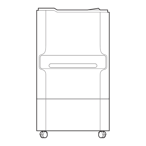
Page 20: Part Name
Ch.1 Before Installation Part Names The names of the DRYPRO 771 parts relevant to installation are set out below. Front, Top and Right Sides 4) Film Ejection Tray 1) Operation Panel 2) Front Cover 5) Air Intake 6) Right Cover... - Page 21 11) Ethernet Port 5) Power Cable Used for network connection. Used to connect the DRYPRO 771 power supply 12) Serial Port Where a backup battery is used, the 6) Power Connector battery cable is connected here.
- Page 22 15) "shift" Key 17) [del/BS] Key 1) "Message Display Window 9) [reset/open] Key Displays the status of DRYPRO 771. Resets the error when it occurs. Opens the front door when a film jam occurs or 2) "operation" Lamp the deodorant filter shall be changed.
- Page 23 Keypad" and [del/BS] key are concealed by service maintenance key cover. Detach this cover when required in installation, maintenance and service work. However, make sure that the cover is put back when the user operates the DRYPRO 771. Slightly push towards the message display window, and lift to remove the cover.
- Page 24 Ch.1 Before Installation Interior Be careful not to pinch 1) Lever-A fingers when lifting the Lever-A 6) Deodorant Filter Case 5) Deodorant Filter 2) Lever-BC Filter Housing (Yellow) 3) Cover-C 4) Film Check Cover 1) Lever-A (Green) 4) Film check cover Locks the deodorant filter case (Between exposure and elevator transport sections)
- Page 25 Ch.1 Before Installation Structure An outline of the structure each of the sections in the DRYPRO 771 is set out below. Film will be transported from 1) through 6) in a printing process. 10) Operation Panel 8) Deodorant Filter 7) Ejection Transport...
- Page 26 Ch.1 Before Installation < 24 > DRYPRO MODEL 771 INSTALLATION MANUAL Ver.1.00 2003.10...
-
Page 27: Ch.2 Unpacking And Installation
Unpacking and Installation This chapter describes the procedure for unpacking and installing the DRYPRO 771. < 25 > DRYPRO MODEL 771 INSTALLATION MANUAL Ver.1.00 2003.10... -
Page 28: List Of Package Contents
Power cable, Clamp (2 pcs), Exhaust duct, Warranty, Operation manual, Operation sheet, Attached document for doctors, Inspection sheet, Protection parts (red parts) recycle bag, Accessory list. DRYPRO 771 Cushioning (under the main body) Pallet Wood Piece (with clamp) p.30 Checking the Accessories <... -
Page 29: Unpacking
Ch.2 Unpacking and Installation Unpacking The procedure for unpacking the DRYPRO 771 is described below. The weight of the DRYPRO 771 is approximately 155kg (without stand) or When disposing of the 175kg(with stand) and the weight of the packing is approximately 189kg (without packing materials, stand) or 205kg (with stand). - Page 30 Remove the wooden restrainer from the bottom of the DRYPRO 771 main body. Using the restrainer as a lever, raise the main body at the front and remove the shock Be extremely careful not absorbers (2) from under the left and right front to jam fingers when side.
- Page 31 Ch.2 Unpacking and Installation Remove the packing bag. With two person steadying the sides of the main body, slowly move the DRYPRO 771 from the palette onto the ramp. Do not stand in the path along which the DRYPRO 771 is moved.
-
Page 32: Checking The Accessories
Ch.2 Unpacking and Installation Checking the Accessories The following parts are packed together with the DRYPRO 771. Check that all the parts listed below are present. Should any parts be missing, the unit should be treated as an erroneous consignment. -
Page 33: Removing Protective Parts (Red)
Ch.2 Unpacking and Installation Removing protective parts (Red) To prevent damage to the internal components of the DRYPRO 771 during shipment due to shock or vibration, the interior of the unit is protected by protective parts. This material should be removed following the procedure detailed below. -
Page 34: Removing Protective Parts From Rear Panel Of Exposure Unit
120mm minimum Front Cover Lock Open the front cover. Press the supply tray open button on the rear panel of the DRYPRO 771 and pull out the supply tray to its furthest extent. Supply tray open button < 32 >... -
Page 35: Removing Protective Parts From The Front Panel Of The Exposure Unit
• Next, remove the protective parts from the front DRYPRO 771. panel of the exposure unit. When handling the interior of the exposure unit, be careful not to cut fingers on the steel belt. -
Page 36: Removing The Protective Film From The Exposure Unit Conveyer
Ch.2 Unpacking and Installation 2.4.4 Removing Protective Film from the exposure unit Conveyor After removal of the protective parts from the front panel of the exposure unit, the two protective films (14x17in) should be removed from the exposure unit conveyor rollers. Press lever-BC down and open the left cover. -
Page 37: Removing Protective Parts From The Rear Panel Of The Exposure Unit
Ch.2 Unpacking and Installation 2.4.5 Removing protective parts from the Rear Panel of the exposure unit How to remove the protective parts from the supply section following the removal of protective films from exposure section is set out below. Remove the six screws securing the supply unit cover and remove the cover. -
Page 38: Attaching The Covers For Supply And Exposure Unit
Ch.2 Unpacking and Installation 2.4.6 Attaching the Covers for Supply and Exposure Sections As soon as the procedures in 2.4.2 through 2.4.5 are completed, attach the covers for supply and exposure sections. Attach the cover for supply section. • Screw the cover to the main body with six screws (TP screws, M3x6). -
Page 39: Removing Protective Sheet From Heat Roller
Ch.2 Unpacking and Installation 2.4.7 Removing Protective Sheet from Heat Roller Following the removal of the protection films for transport rollers at the exposure unit, remove each of 14 x 14in film and cushioning sheet (mirror matte). Remove the three screws securing the cover at the top of rear panel, and remove the rear cover. - Page 40 Ch.2 Unpacking and Installation Remove the upper rack. Be careful not to scratch or damage the heat- developer drum with the upper rack when removing. • Hold both sides of the upper rack when removing, as shown in the illustration. Slightly lift up (15mm) the front of the heat process drum shaft.
-
Page 41: Adjusting The Cleaner Unwoven Cloth
Ch.2 Unpacking and Installation 2.4.8 Adjusting the Cleaner Unwoven Cloth If it is found that the cleaner unwoven cloth is wavy when removing the protective sheet for the heat processing drum, manually rewind the unwoven cloth to remove the waviness by moving the cleaning retraction motor. - Page 42 Ch.2 Unpacking and Installation Installing the Parts How to install the parts which were removed for adjustment of the unwoven cloth is set out below. While pressing the gear of the cleaning retraction motor against the gear of the cleaner rewind shaft, tighten the screws of the cleaning retraction motor.
-
Page 43: Attaching The Outer Covers
Ch.2 Unpacking and Installation 2.4.9 Attaching the Outer Covers Attach the outer covers after completing the removal of protective parts. Replace the heat processing cover to the original position, and secure it with four screws (TP screws, M3x6). • Hold the both side, and attach the heat processing cover as illustrated in the left. - Page 44 Ch.2 Unpacking and Installation Attach the rear top cover. • Secure it to the main body with three screws (truss screw, M4x12). Attach the front cover unlock cover. Make sure that the front cover unlock cover, screws, etc. that were once removed are installed to the original position after the work.
-
Page 45: Installing The Accessories
2.5.1 Installing the Deodorant Filter • Deodorant Filter Case Install the deodorant filter and deodorant filter case delivered in the packing of DRYPRO 771. Take out the deodorant filter and deodorant filter case from the accessory box delivered with the packing. - Page 46 Ch.2 Unpacking and Installation Set the deodorant filter in the deodorant filter case. • Insert the filter assembly deeply into the filter case with holes on the corrugated cardboard facing up as shown in the figure. Turn lever-A down to the right. Close the front cover.
- Page 47 The supply size stopper set at the factory is for 14 x 17in. Press the supply tray open button on the rear panel of the DRYPRO 771 and open the supply tray. Supply tray open button Pull the tray out to its furthest extent and open the light blocking cover.
- Page 48 UPS battery can endure, it suddenly turns off. If the power is abruptly shut down while the DRYPRO 771 is in operation, data such as film data may not be kept correct.
- Page 49 Connection with the DRYPRO 771 (recommended UPS battery) Rear side of DRYPRO 771 Power OFF the DRYPRO 771. Connect a serial cable to the serial connector located on the rear panel of the DRYPRO 771. Serial Connector Connect to the UPS battery, the other end of the...
- Page 50 Ch.2 Unpacking and Installation 2.5.5 Installing the Exhaust Duct How to install the exhaust duct is detailed below. This duct should be installed according to the requirement. Installation of the exhaust duct can drive the exhaust flow downward as well as decrease the exhaust fan noise.
-
Page 51: Start Up
Ch.2 Unpacking and Installation Start Up After completing the removal and installation of specified parts, start up the DRYPRO 771. 2.6.1 Turning ON the Power Turn on the power of the DRYPRO 771. Make sure that the power breaker located in the lower left of the jam release-port cover. - Page 52 Do not place objects on or lean on the supply tray when removed from the DRYPRO 771: doing so may cause damage. Slowly pull out the supply tray fully. Open the light-blocking cover on the supply tray.
- Page 53 Ch.2 Unpacking and Installation Insert the top edge (far edge) of the package firmly between the restrainer and winding axis. Ensure that the bottom edge (near edge) of the package protrudes from the light blocking cover and firmly close the light-blocking cover. Do not touch the knob on the light- blocking cover.
- Page 54 Ch.2 Unpacking and Installation < 52 > DRYPRO MODEL 771 INSTALLATION MANUAL Ver.1.00 2003.10...
-
Page 55: Ch.3 Settings
Settings This chapter describes the procedure for making DRYPRO 771 settings. < 53 > DRYPRO MODEL 771 INSTALLATION MANUAL Ver.1.00 2003.10... -
Page 56: Outline Of Drypro 771 Settings
: Registration of diagnostic devices connected to the DRYPRO 771 and DICOM information, N-EVENT REPORT settings for those devices. • S20 PRINT CONDITION : Print parameter settings for each of the diagnostic devices connected to the DRYPRO 771. • S30 DICOM PRIORITY : DICOM data enabling/disabling settings. -
Page 57: Starting The Service Maintenance Mode
Once the service maintenance mode has been started up, it will remain activated either until it is exited or until the DRYPRO 771 power supply is shut down. < 55 > DRYPRO MODEL 771 INSTALLATION MANUAL Ver.1.00 2003.10... -
Page 58: Closing The Service Maintenance Mode
Select "U90 PASSWORD" in the user switching off the maintenance mode. DRYPRO 771 power • The message "U90 PASSWORD" will be displayed U90 PASSWORD supply. in the message display window. Press the [enter] key. -
Page 59: Dicom Scp Settings
Ch.3 Settings DICOM SCP Settings Service Manual S00 DICOM SCP Web Maintenance The procedure for making DICOM SCP (DICOM information for the DRYPRO 771 only) settings is Tool> described below. Network> The following DICOM SCP items may be set. DICOMSCP... - Page 60 Pressing the [mode] key will switch the input mode between alphabetical characters and numerical digits. Selecting either of following will automatically restart the DRYPRO 771. S05 IP ADDRESS S06 SUBNET MASK S07 GATEWAY S0A HOST NAME S0B DHCP When [exit] key is pressed in the "DICOM SCP Setting", a confirmation screen will be...
-
Page 61: Dicom Scu Settings
: Sets the name of the selected diagnostic device. A maximum of 12 alphanumerical characters may be input. The name set here is used in the DRYPRO 771 only and will be displayed as the diagnostic device name. • S13 N-EVENT PORT : Sets the N-EVENT PORT number.default setting : 00000... - Page 62 Select from "OFF" (as in the past) and "ON" (tone conversion using "P" value) . default setting : OFF Relation among Status of the DRYPRO 771, "DICOM ERR LV" setting and communication with external devices. Ready for print • warming up (including the case where "S19 EMPTY NOTICE"...
- Page 63 CH 1 CS-1 [select] key. Press the [enter] key after completing all input and settings. • The setting will be saved, and the DRYPRO 771 will automatically shutdown so that the settings become valid. Press the operation switch to Pressing the [mode] restart.
-
Page 64: Print Condition Settings
Ch.3 Settings S21 - S2B PRINT CONDITION Settings S20 PRINT COND. Service Manual The procedure for setting printing parameters for each of the diagnostic devices connected is Web Maintenance described below. Tool> Following items for PRINT CONDITION needs to be set. SCU>... - Page 65 Ch.3 Settings • S2F REQ. BEHAVIOR : Select the action when the image size sent from the connected device is larger than the installed film size. Select from "DECIMATE" (proportional display) and "CROP" (length display). Selecting "DECIMATE" prints a reduced image by fitting the image size to the film.
- Page 66 Ch.3 Settings p.38 Starting up the Start up the service maintenance mode. Service Maintenance Mode U80 SERVICE MODE Select "U80 SERVICE MODE" and press the [enter] key. • The message "S00 DICOM SCP" will be displayed. S00 DICOM SCP Press the lower [menu/select] key twice. •...
-
Page 67: Setting The Print Quality (U50, U60, U30)
Ch.3 Settings Setting the Print Quality (U50, U60, U30) How to set the quality of the print image of DRYPRO 771 is set out below. Outline of LUT Setting Outline of LUT generated on the DRYPRO 771 is described below. - Page 68 How to copy the LUT of library on the User LUT is set out below. To apply the LUT in the library directly to the LUT of the DRYPRO 771, procedures in "(1) Copying the Library LUT to User LUT and (2) Editing the User LUT curve point by point" are not necessary.
- Page 69 (2) Manipulating the User LUTs Point by Point While the DRYPRO 771 is furnished with a LUT library designed to match diagnostic devices, the user may also set up custom LUTs by inputting the values for each point of LUT curve.
- Page 70 Ch.3 Settings (3) Applying the LUT in the LUT Library to each CH of the DRYPRO 771. Applies the LUT in the library, which is prepared in advance or the User LUT to any of channel 1~7 through which the external device is affected by the LUT.
- Page 71 Ch.3 Settings List of LUT Library LUTs listed in the library that is incorporated in the DRYPRO 771 at the factory is shown below. LUT Name Modality Film Description CT&MR_KC_B LUT of our recommendation for blue base film on CT/MR.
- Page 72 Ch.3 Settings (4) Selecting the standard LUT which will be used by each channel. Set the standard LUT that will be used when the LUT is not specified by the external device or when "S31DEFAULT LUT" is set "P-CON". At the same time, "U30 PRINT COND." of the user maintenance mode is set. Set the print condition for each diagnostic device to handle the case where there is no print condition specified by the diagnostic device.
- Page 73 Ch.3 Settings Start the maintenance mode. Press [d] of the [menu/select] key three times. • "U30 PRINT COND" will be displayed. U30 PRINT COND. CH 1 MRI-1 Select the diagnostic device using [select] key [[][\], and press the [enter] key. •...
-
Page 74: Dicom Priority Settings
Ch.3 Settings Service Manual DICOM PRIORITY Settings S30 DICOM PRIORITY/. Web Maintenance The procedure for making DICOM data enable/disable settings is described below. Tool> The following DICOM PRIORITY setting items are available for selection. SCU> PRIORITY SETUP • S31 DEFAULT LUT : This setting enables or disables the default LUT selection. - Page 75 Ch.3 Settings p.38 Starting up the Start up the service maintenance mode. Service Maintenance Mode U80 SERVICE MODE Select "U80 SERVICE MODE" and press the [enter] key. • The message "S00 DICOM SCP" will be displayed. S00 DICOM SCP Press the lower [menu/select] key three times. •...
-
Page 76: Film Setup Settings
Ch.3 Settings Service Manual FILM SETUP Settings S40 FILM SETUP Web Maintenance The procedure for setting the output film size and type for the DRYPRO 771 is described below. Tool> The following FILM SETUP items are available. SCP> FILM SETUP S41 Film Size : Select the film size. -
Page 77: System Setup Settings
Ch.3 Settings 3.10 SYSTEM SETUP Settings The procedure for setting the items relating to system operation of the DRYPRO 771 is described below. Service Manual The following SYSTEM SETUP items are available. web maintenance tool>SCP> SYSTEM SETUP Item Default Contents... - Page 78 Ch.3 Settings p.55 Starting the Start the maintenance mode. Service Maintenance Mode U80 SERVICE MODE Display "U80 SERVICE MODE", and press the [enter] key. • "U00 DICOM SCP" will be displayed on the message display window. S00 DICOM SCP Press [d] of the [menu/select] key seven times. •...
- Page 79 Ch.3 Settings List of Time Zone Time zone and time code for "S73 TIME ZONE" are listed below. Summer Summer Time Code Time Zone Time Code Time Zone Time Time Afghanistan Standard Time Israel Standard Time Alaskan Standard Time Korea Standard Time Arab Standard Time Mexico Standard Time Arabian Standard Time...
-
Page 80: 3.11 Checking The Internal Clock
Ch.4 Checking the Image 3.11 Checking the Internal Clock UA0 TIME SET Check the iternal clock of the DRYPRO 771, and correct if necessary. Set "YEAR", "MONTH", "DAY", "HOUR" and "MINUTES". Operation Manual> Start the maintenance mode. Maintenance Mode>Time Setting UA0 TIME SET Press [d] of the [menu/select] key ten times. -
Page 81: Shedule Setting
Ch.3 Settings Service Manual 3.12 SCHEDULE Setting SG0 SCHEDULE Web Maintenance How to initialize the maintenance and check schedule of the DRYPRO 771 is detailed below. Tool> Schedules to be initialized are following. SCP> SCHEDULE • MNT. A RESET : Initializes the check schedule (40,000 prints or 2 yrs), and sets back to the factory settings. - Page 82 Ch.4 Checking the Image < 80 > DRYPRO MODEL 771 INSTALLATION MANUAL Ver.1.00 2003.10...
-
Page 83: Ch.4 Checking The Image Quality
Checking the Image Quality This chapter describes the procedure for checking the image quality.. < 81 > DRYPRO MODEL 771 INSTALLATION MANUAL Ver.1.00 2003.10... -
Page 84: Correction Of Incorporated Densitometer
Ch.4 Checking the Image Quality Correction of Incorporated Densitometer After completing the installation and settings of the DRYPRO 771, load the films in the supply tray, and print the test pattern to correct the density. When a densitometer is available at the facility, use it. If it is not available, use the one you bought with. - Page 85 Ch.4 Checking the Image Quality Display the input fields "POINT01" ~ "POINT10"through "INPUT DENSITY" of the service maintenance mode "S50" again, and check that the inputs are correct. Print out a calibration sheet using the service maintenance mode "S60". • Bring the Service Maintenance Mode "S60 TEST PRINT"...
-
Page 86: Test Print
Ch.4 Checking the Image Quality Test Print After completing the density correction of the DRYPRO 771, check the printed image by implementing the test print. At the occasion of installation, check the image by printing two flat patterns and one SMPTE pattern. - Page 87 Ch.4 Checking the Image Quality Input the copy count using the ten key, and press the [enter] key. S62 COPY COUNT • Input "1" at the installation. [01] • Print queue will be registered, and the screen returns to the maintenance menu screen. •...
- Page 88 Ch.4 Checking the Image Quality 4.2.2 Print the SMPTE pattern To check the density on the printed film, print a SMPTE pattern. Start the maintenance mode. Press [d] of the [menu/select] key once. • "U10 TEST PATTERN" will be displayed. Use the [select] key [[][\] to choose the channel.
- Page 89 Judging the Density of SMPTE Pattern Measure the density of the printed SMPTE pattern, and judge that the output density of the DRYPRO 771 is normal. Among the eight step wedges, measure the density of either of the four step wedges located in the center with a densitometer If the measurement falls within +/- D=0.05 of the...
- Page 90 Ch.4 Checking the Image Density Linearity Criterion Correction 1 Difference Correction 2 Difference 2 2 2 2 0 0 0 0 3 3 3 3 9 9 9 9 5 5 5 5 7 7 7 7 7 7 7 7 6 6 6 6 9 9 9 9 5 5 5 5 1 1 1 1 1 1 1 1 3 3 3 3 1 1 1 1 3 3 3 3 2 2 2 2...
-
Page 91: Ch.5 Print Commanded From The External Device And Backup
Print Commanded from the External Device and Backup This chapter describes the procedure for print commanded from the external device and backup. < 89 > DRYPRO MODEL 771 INSTALLATION MANUAL Ver.1.00 2003.10... -
Page 92: Print Commanded From The External Device
Ch.5 Print Commanded from the External Device and Backup Print Commanded from the External Device The procedure for connection of DRYPRO 771 power supply and network cables is described below. Connect one end of the ethernet cable to the ethernet port (RJ45) located on the rear panel of the DRYPRO 771. - Page 93 5.2.1 Backing Up the CF Memory Data (CF→ → HDD) How to back up the program and set up files of the DRYPRO 771 for the safety sake prepared for the damage of the CF memory is set out below.
- Page 94 Start the maintenance PC. Start the internet Explorer (ver. 5.0 or later) • Message "Page not found" will be displayed. Input the DRYPRO 771's IP address in the "Address (D)" box following "http://". • Input the address in the following format.
- Page 95 Ch.5 Print Commanded from the External Device and Backup Click [SERVICE] in the [MODE] field, and input the service privileged password (5678) in the "PASSWORD" input box. • Input password will not be displayed. Only "*" will be shown instead of figures. •...
- Page 96 Ch.4 Checking the Image < 94 > DRYPRO MODEL 771 INSTALLATION MANUAL Ver.1.00 2003.10...
-
Page 97: Specifications
Specifications This chapter details the specifications of the DRYPRO 771. < 95 > DRYPRO MODEL 771 INSTALLATION MANUAL Ver.1.00 2003.10... - Page 98 Specification Product Name Laser Imager DRYPRO MODEL 771 CODE No. : 0582 : 0583 Model DRYPRO MODEL 771 Laser Source Semiconductor Laser Film Type Medical Imaging Film SD-P, SD-PC, DR-P Film Size 14 X 17 inch 14 X 14 inch 11 X 14 Inch Size to be determined when unit is installed.
- Page 99 IEC60601-1-2 : 2001, IEC60601-1, IEC60825 Standards Remarks DRYPRO 771 is manufactured in factories certified in compliance with ISO9001 : 2000, EN ISO13485 : 2000, 93/42/EEC quality control standards as well as with medical device directive FDA Pre market Notification 510(k) and GMP.
- Page 100 D-85662 Hohenbrunn, GERMANY TEL.973-633-1500 TEL.905-670-7722 TEL.8102-8040 KONICA FRANCE S.A. Konica Minolta Photo Imaging UK Ltd. Paris Nord II, 305 rue de la Belle Etoile, B.P. 50077, 95948 Plane Tree Crescent, Feltham, Middlesex ROISSY C.D.G. CEDEX, FRANCE TW13 7HD, U.K. TEL.1-4938-6550 TEL.20-8751-6121...
Need help?
Do you have a question about the DRYPRO 771 and is the answer not in the manual?
Questions and answers