Table of Contents
Troubleshooting

Related Manuals for CareFusion AVEA


Summary of Contents for CareFusion AVEA
- Page 1 AVEA ventilator systems ® Operator’s manual...
- Page 2 This document may not be copied, reproduced, translated, stored in a retrieval system, transmitted in any form, or reduced to any electronic medium or machine-readable form, in whole or in part, without the written permission of CareFusion. Information in this document is subject to change without notice.
- Page 3 Changed the logo and company references to VIASYS. January 2011 Changed the logo and company references to CareFusion. January 2011 Added content for Volume Guarantee and Nasal Intermittent Mandatory Ventilation. June 2011 Removed the first note from the section “Specific Controls”...
- Page 4 Two (2) years or 16,000 hours, whichever occurs first. The liability of CareFusion (referred to as the Company) under this warranty is limited to replacing, repairing or issuing credit, at the discretion of the Company, for parts that become defective or fail to meet published specifications during the warranty period;...
-
Page 5: Table Of Contents
Setting Up the Front of the Ventilator ...................... 9 Front Panel Connections ........................17 Setting Up the Rear of the Ventilator ....................24 User Verification Test ..........................39 AVEA User Verification Test Checklist....................45 AVEA Troubleshooting .......................... 46 Chapter 3: Ventilator Operation ....................51 Membrane Buttons and LEDs ....................... -
Page 6: Table Of Contents
Hot Wire Flow Sensor Specifications ....................218 Circuit Resistance Test ........................219 Volumetric Capnography Specifications ..................... 220 Appendix F: AVEA Message Bar Text ..................221 Appendix G: Advanced Pulmonary Mechanics Monitored Parameters ........223 Appendix H: Capnometry Troubleshooting ................231... -
Page 7: Regulatory Notice
• Use of other cables may result in increased emissions or decreased immunity. See Tables 201, 202, 203, and 205 for further information regarding the AVEA Ventilator and EMC. MRI Notice This equipment contains electromagnetic components whose operation can be affected by intense electromagnetic fields. - Page 8 AVEA ventilator systems Manufactured by: CareFusion 22745 Savi Ranch Parkway Yorba Linda, California 92887-4668 If you have a question regarding the Declaration of Conformity for this product, please contact CareFusion at one of the numbers given in Appendix A. L2786 Rev. M...
-
Page 9: Safety Information
Warnings and Cautions appear throughout this manual where they are relevant. The Warnings and Cautions listed here apply generally any time you operate the ventilator. The AVEA Ventilator is intended for use by a trained practitioner, under the direction of a qualified physician. •... - Page 10 To avoid electrical shock, plug the power cord into a properly wired receptacle, use only the power cord supplied with the ventilator, and make sure the power cord is in good condition. The AVEA is designed to ensure that the user and patient are not exposed to excessive leakage current per applicable •...
- Page 11 AVEA ventilator systems Equipment Symbols The following symbols may be referenced on the ventilator or in accompanying documentation Symbol Source/Compliance Meaning Symbol #03-02 IEC 60878 Indicates ATTENTION, consult ACCOMPANYING DOCUMENTS This symbol indicates a FUSE. Symbol #5016 IEC 60417 Symbol #5034 IEC 60417 This symbol indicates INPUT.
- Page 12 Operator's manual MAIN SCREEN CareFusion Symbol EVENT READY Symbol #417 IEC 5102 MODE CareFusion Symbol ADVANCED SETTINGS CareFusion Symbol SET-UP for patient size selection CareFusion Symbol CE Mark MDD Directive 93/42/EEC ALARM RESET Symbol #5307 IEC 60417 ALARM SILENCE Symbol #5319 IEC 60417...
- Page 13 AVEA ventilator systems Enable the ALARM LIMITS screen CareFusion symbol This symbol indicates a CONTROL LOCK. CareFusion symbol NEBULIZER port CareFusion symbol Increase OXYGEN CareFusion symbol PRINT SCREEN CareFusion symbol SUCTION port CareFusion symbol VARIABLE ORIFICE FLOW SENSOR connection...
- Page 14 This symbol indicates an INTERNAL BATTERY FUSE CareFusion symbol This symbol indicates ALARM LOUDNESS CareFusion symbol This symbol indicates that the AVEA is being powered by the CareFusion symbol INTERNAL BATTERY only. This symbol indicates that the HELIOX configuration is in use.
-
Page 15: Chapter 1: Introduction
The AVEA has been designed to function using most commonly available accessories. It is easy to clean and its design does not allow liquids to pool on the casing, reducing the likelihood of fluid leakage into the body of the ventilator. - Page 16 When Artificial Airway Compensation is turned on, the ventilator automatically calculates the pressure drop across the endotracheal tube. The AVEA then adjusts the airway pressure to deliver the set inspiratory pressure to the distal (carina) end of the endotracheal tube. This calculation takes into account flow, gas composition (Heliox or...
- Page 17 AVEA ventilator systems Chapter 1: Introduction Full range of Patient Size You can select a patient size of Adult, Pediatric, or Neonate. Once the selection is made, the ventilator offers only those parameters, which are available for your selected patient size.
- Page 18 Heliox Delivery (Comprehensive only, option on Standard) Using patented “Smart” connector technology, the Comprehensive model AVEA can deliver Heliox blended gas instead of Medical air. By simply changing a connector on the back panel, the ventilator identifies the gas input and adjusts to accommodate the change.
- Page 19 AVEA ventilator systems Chapter 1: Introduction WARNING Connection of a gas supply at the Helium-Oxygen mixture inlet that does not contain 20% oxygen can cause hypoxia or death. Although an 80/20 mixture of Helium and Oxygen is marketed as medical gas, the Helium/Oxygen gas mixture is not labeled for any specific medical use.
- Page 20 Chapter 1: Introduction Operator's manual This page intentionally left blank. L2786 Rev. M...
-
Page 21: Chapter 2: Unpacking & Setup
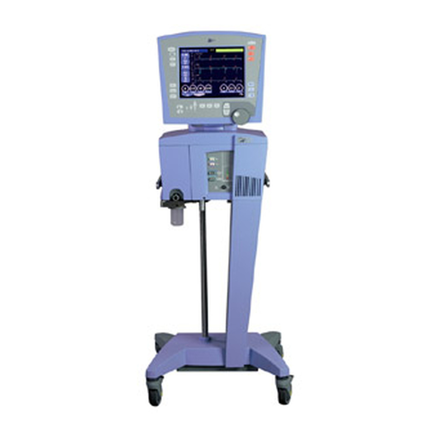
Heliox Inlet fitting CGA DISS-type body, No. 1180 (Heliox) Note: NIST fittings for air and oxygen are available from CareFusion upon request at the time of the order. Oxygen Supply Pressure Range: 20 to 80 psig (1.4 to 5.5 bar) (Supply Oxygen) Temperature: 5 to 40º... - Page 22 Operator's manual Assembling the Ventilator Assemble your AVEA ventilator’s wheeled base using the instructions included in the package. The ventilator body is easily attached to the base by means of four thumbscrews. Reference the AVEA Service Manual Installation Instructions for detailed directions (Figure 2–1).
-
Page 23: Setting Up The Front Of The Ventilator
Chapter 2: Unpacking and Setup External battery option If you have purchased the optional external battery pack, reference AVEA Service Manual, Installation Instructions. Install your external batteries per the installation instructions enclosed with the cart accessories kit (P/N 11372). Setting Up the Front of the Ventilator... - Page 24 Chapter 2: Unpacking and Setup Operator's manual Align the locating ridge on the water trap assembly with the slot in the exhalation filter cartridge (Figure 2–4). Slot matches locating ridge of water trap assembly Figure 2–4: Exhalation Filter Cartridge Showing Locating Slot Slide the water trap/exhalation filter assembly into the cartridge (Figure 2–5).
- Page 25 AVEA ventilator systems Chapter 2: Unpacking and Setup Rotate the metal locking lever on the lower right of the ventilator body forward to an open position. Figure 2–6: Open locking lever Insert the completed cartridge assembly into the ventilator body as shown. Make sure it is completely seated in the well.
-
Page 26: User Instructions
Installation Note: The AVEA Disposable Expiratory Filter / Water Trap is supplied non-sterile. It can be used as an alternative for the AVEA reusable filter assembly (reusable filter, a collector vial, a water trap, and a cartridge component). The AVEA reusable filter assembly is not required when using the Disposable Expiratory Filter / Water Trap. - Page 27 After you close the locking lever, the filter is ready for use. Figure 2–12: Completed installation of Filter / Water Trap combination WARNING Incomplete insertion of the AVEA Disposable Expiratory Filter may cause misalignment of the filter seal, which will result in patient circuit leakage. Note: The lever closes without great difficulty if the filter is fully inserted into the filter cavity.
- Page 28 Chapter 2: Unpacking and Setup Operator's manual Drain Tube and Pinch Clamp. Inspect for any visible damage and make sure it is securely installed. Periodically inspect the filter-vial water level and empty it before it reaches the maximum-level line. To empty the fluid in the collection vial, press open the pinch clamp to empty contents of the collection vial into an appropriate receptacle.
-
Page 29: Additional Information
INSPECTION: Inspect for any visible damage to the plastic housing or the folded filter media before use. Discard if there is any damage. REPLACEMENT: AVEA Disposable Exhalation Filter, including the drain tube and the pinch clamp are single use items. Replace with a new unused filter at each circuit change. - Page 30 Using an active humidifier, the adult patient circuit is set up as shown in Figure 2–16. Attach your humidifier to the upright pole of the AVEA base. Adjust the height of the humidifier and the length of the humidifier tubing so that the tubing is relatively Inspiratory straight with no occlusions.
-
Page 31: Front Panel Connections
Neonatal Patient Circuit The Neonatal Patient Circuit is attached as shown in Figure 2–18. Inspiratory Limb of Patient Circuit Figure 2–18: Neonatal Patient Circuit Front Panel Connections Comprehensive Standard Figure 2–19: AVEA Front Panel Configurations Standard & Comprehensive L2786 Rev. M... - Page 32 Attaching Flow Sensors The AVEA can accept either a hot wire or a variable orifice proximal flow sensor. These are in addition to the instrument’s internal inspiratory flow sensor and heated expiratory flow sensor. Three proximal flow sensors are available for the AVEA.
- Page 33 Variable orifice flow sensors are also available on some AVEA models. The neonatal VarFlex flow sensor is compatible in neonatal and pediatric applications where the peak inspiratory flow rate is less than 30L/min and is not active in adult applications.
- Page 34 Chapter 2: Unpacking and Setup Operator's manual Variable Orifice Flow Sensor Variable Orifice sensors attach to the receptacle on the front panel of the ventilator circled in dark blue and marked with the icon shown here. This is a locking connector. To attach, first pull back the plastic locking collar, then push firmly onto the ventilator receptacle.
- Page 35 Figure 2–22: Attaching nebulizer tubing Note: To use the internal nebulizer, the AVEA must be connected to a high-pressure air source. The nebulizer is not active while the AVEA is operating on its internal compressor. The ventilator incorporates an internal pneumatic compressor, which creates the drive pressure necessary to operate the nebulizer.
- Page 36 A proximal pressure sensor to monitor proximal airway pressure can be attached to the Comprehensive model of AVEA. On the Comprehensive AVEA the connector is labeled as Aux as shown in Figure 2–23 and is circled in purple. When active, this feature will display & alarm to proximal airway pressures.
- Page 37 See “Chapter 4: Monitors, Displays and Maneuvers” for placement technique for esophageal balloons. Tracheal Catheter A tracheal catheter will attach to the AVEA at the connection on the front panel marked as Aux. The connector is shown in Figure 2–23.
-
Page 38: Setting Up The Rear Of The Ventilator
Chapter 2: Unpacking and Setup Operator's manual Setting Up the Rear of the Ventilator Figure 2–25: Rear panel AC power module Oxygen hose connection UIM connection External battery connector Analog input/output/ILV External battery fuse Power ON/OFF Switch Internal battery fuse Nurse call system connection Air/Heliox smart connector Oxygen sensor... - Page 39 AVEA ventilator systems Chapter 2: Unpacking and Setup Connecting the Oxygen Sensor O2 Cell The oxygen sensor cell is located on the rear panel, between the two gas fittings. The oxygen sensor cable emerges from the rear panel directly above the sensor.
- Page 40 Figure 2–28: Attaching the Tethered Heliox Connector The AVEA “Smart” connectors signal to the ventilator which type of fitting is attached and therefore which gas controls to initiate. The fitting on the right of the panel is for attaching the Oxygen gas source. The O fitting type is CGA DISS type, No.
- Page 41 Figure 2–31. The fitting shown here is a DISS fitting. Fittings which accept NIST and Air Liquide hoses are also available from CareFusion. The air hose will not attach to the fitting designed for Heliox and vice versa.
- Page 42 Chapter 2: Unpacking and Setup Operator's manual Utilities Screens Configuration Tab Figure 2–32: Utilities Screen Alarm Loudness. To change alarm sound levels depress and hold the increase or decrease soft keys until the desired level is reached. The “Alarm Test” banner will appear during the adjustment. Enable / Disable O2 Alarm.
- Page 43 Setting up Independent Lung Ventilation (ILV) The AVEA has a 25 pin receptacle on the rear panel (Figure 2–33) to allow for Independent Lung Ventilation (ILV) .with another AVEA. The output for ILV provides a 5VDC logic signal synchronized to the breath phase of the master ventilator.
- Page 44 To connect two AVEA ventilators together for independent lung ventilation function, the cable must be wired so that the ILV input (the slave) on one AVEA is connected to the ILV output (the master) on the other AVEA. As shown in Figure 2–33 below, the ILV slave is pin 18, and the ILV master is pin 6.
- Page 45 AVEA ventilator systems Chapter 2: Unpacking and Setup Note: At least one analog ground is required for safe and accurate signal output and input. One analog ground is sufficient for any and all of the other signals. Selecting Language .
- Page 46 Chapter 2: Unpacking and Setup Operator's manual Input/Output Tab Figure 2–35: Utility Screen, Input / Output Tab L2786 Rev. M...
- Page 47 AVEA ventilator systems Chapter 2: Unpacking and Setup Analog Input Configuration Under the heading “Set Analog Input Scale” there are two buttons representing two possible voltage ranges. If the full-scale output of the device you are interfacing with is less than 1 volt, select the 0-1 volt scale button.
- Page 48 Chapter 2: Unpacking and Setup Operator's manual Analog Outputs Set Analog Output Type The analog output flow signal can be selected between Wye Flow (calculated flow to the patient) or Machine Flow (the flow measured by the inspiratory flow sensor within the ventilator). Pressure, Flow, Volume, Breath Phase Figure 2–37: Analog Outputs Pin configuration The pin configuration for pressure, flow, volume and breath phase analog outputs is shown above.
- Page 49 AVEA ventilator systems Chapter 2: Unpacking and Setup Table 2–1: ILV and Analog I/O pin configuration FUNCTION Analog Input Channel 0 Analog Input Channel 1 ILV In ILV Out Factory Use Only. DO NOT CONNECT. Analog Output, PRESSURE Analog Output, FLOW...
- Page 50 Chapter 2: Unpacking and Setup Operator's manual VueLink RS-232 Output: Select Off Figure 2–40: Utility Screen, Input / Output Tab, Vuelink RS-232 Output VOXP Select VOXP and either 8,N,1 / 7,N, 1 / 7, E, 1 or 7, 0, 1 and Baud Rates of: 9600, 19200, 38400, 57600, 115200 Figure 2–41: Utility Screen, Input / Output Tab, VOXP RS-232 Output L2786 Rev.
- Page 51 Nurse Call Connection The AVEA can be connected to a remote nurse call system via the modular connector on the rear panel shown in Figure 2–25, E. The jack is configured to interface with normally closed (NC, open on alarm) or normally open (NO, closed on alarm) signals.
- Page 52 Chapter 2: Unpacking and Setup Operator's manual Powering up the AVEA To power up the ventilator, connect the power cord to a suitable AC power supply and turn on the power switch located on the back panel of the ventilator as shown here.
-
Page 53: User Verification Test
AVEA ventilator systems Chapter 2: Unpacking and Setup User Verification Test WARNING The User Verification Test should always be performed off patient. The User Verification Test consists of the three following sub-tests and should be performed before connection to a new patient. - Page 54 Chapter 2: Unpacking and Setup Operator's manual The Extended Systems Test (EST) The EST function is accessed from the Setup screen as shown here. Press the SETUP membrane button to the lower left of the UIM to open this screen. Figure 2–44: Setup Screen Press the EST touch screen button to select it.
- Page 55 Chapter 2: Unpacking and Setup The “SET UP ACCEPT” key must be pressed in order for the AVEA to retain the circuit compliance measurement. At this point, even after power cycling off, if “SAME PT” is selected, the circuit compliance measurement will continue to be retained.
- Page 56 Chapter 2: Unpacking and Setup Operator's manual 6. Verify that no alarms are active and clear the alarm indicator by pressing the alarm reset button on the upper right of the user interface. 7. Set the % O control to 100%. Disconnect the Oxygen sensor from the back panel of the ventilator and verify that the Low O alarm activates.
- Page 57 AVEA ventilator systems Chapter 2: Unpacking and Setup Default Settings for Adult, Pediatric and Neonate The Default settings are the operational settings that take effect when you press the New Patient button on power up. Ventilation Setup Adult Setting Pediatric Setting...
- Page 58 Chapter 2: Unpacking and Setup Operator's manual Adult Setting Pediatric Setting Neonate Setting PSV Tmax 5 sec 0.75 sec 0.35 sec Machine Volume 0 ml 0 ml (Mach Vol) Volume Limit 2.50 L 500 ml 300.0 ml (Vol Limit) Inspiratory Rise (Insp Rise) Flow Cycle 0% (off)
-
Page 59: Avea User Verification Test Checklist
AVEA ventilator systems Chapter 2: Unpacking and Setup AVEA User Verification Test Checklist Machine Serial Number:________________________________ Test Date: __________________ PASS FAIL TEST Automated Tests Power-on self test Patient circuit leak test Patient circuit compliance measurement Two point calibration of the oxygen sensor... -
Page 60: Avea Troubleshooting
Chapter 2: Unpacking and Setup Operator's manual AVEA Troubleshooting Remove ventilator from patient with any potential problem Symptom Problem Solution(s) Will not pass EST - Fails Leak Circuit wye not fully occluded Ensure circuit wye is fully occluded Leak in patient circuit Check for leaks in circuit and reseat circuit connections to ventilator. - Page 61 AVEA ventilator systems Chapter 2: Unpacking and Setup Symptom Problem Solution(s) Volume waveform above or below Humidifier "Active on/off" set Set for "Active on” for humidifier, baseline on patient with internal incorrectly "Active off" for “HME" sensor Normal if readings are within...
- Page 62 Chapter 2: Unpacking and Setup Operator's manual Symptom Problem Solution(s) Improper charge level indicator - Excessively discharged battery Requires at least 12 hours for full External battery charge Loose connections Check connections Decreased run time on battery Battery not fully charged Internal battery requires at least 4 hours for full charge.
- Page 63 AVEA ventilator systems Chapter 2: Unpacking and Setup Symptom Problem Solution(s) Low NCPAP Pressure Circuit disconnect Check circuit Circuit leak Check patient interface Patient interface leak High NCPAP Pressure Patient circuit occlusion Check patient circuit Water in circuit Check nasal prongs...
- Page 64 Chapter 2: Unpacking and Setup Operator's manual This page intentionally left blank L2786 Rev. M...
-
Page 65: Chapter 3: Ventilator Operation
AVEA ventilator systems Chapter 3: Ventilator Operation Membrane Buttons and LEDs Figure 3.1a User Interface Module (International) Showing Button Icons L2786 Rev. M... - Page 66 Chapter 3: Ventilator Operation Operator's manual Figure 3.1b User Interface Module (English) Showing Button Labels Figure 3–1: User Interface Module The Membrane buttons are the UIM controls, which surround the Touch Screen. Moving clockwise around the UIM from the top right (see arrow), they are: Alarm Silence (LED) Pressing this button will disable the audible portion of an alarm for 2 minutes (±...
- Page 67 AVEA ventilator systems Chapter 3: Ventilator Operation Alarm Limits Opens the alarm limits screen for data entry or adjustment. Toggles the screen on and off. Note: Pressing the Freeze button while the Alarm Limits window is open will automatically close the window and freeze the graphics.
- Page 68 Chapter 3: Ventilator Operation Operator's manual To configure the Increase F Access the Configuration tab on the Utilities Screen: Increase F Configures the step increase used during the increase oxygen maneuver. Sets the amount of oxygen the ventilator will increase above the current set F Example: If the Increase F is set at 20%...
- Page 69 AVEA ventilator systems Chapter 3: Ventilator Operation J. Expiratory Hold When the EXP HOLD button is pressed, at the start of the next breath interval the ventilator will not allow the patient to inspire or exhale for a maximum of 20 seconds (adult/pediatric) for breath rates 20 and less, 25 seconds for breath rates greater than 20, or 3 seconds (neonate).
- Page 70 Chapter 3: Ventilator Operation Operator's manual Panel Lock (LED) The LOCK key disables all front panel and screen controls except MANUAL BREATH, Suction,↑ %O , ALARM RESET, ALARM SILENCE, and LOCK. Print The PRINT key outputs the contents of the currently displayed screen to a suitably connected parallel printer. Set-up Opens the ventilator Setup screen.
- Page 71 AVEA ventilator systems Chapter 3: Ventilator Operation T. Freeze The FREEZE key freezes the current screen and suspends real-time update of screen data until pressed again. While the screen is frozen, a scrollable cursor appears. The Data Dial can be used to scroll the cursor through data points on waveform, loop or trend screens.
- Page 72 Chapter 3: Ventilator Operation Operator's manual Screens Opens the Screen Selection box (Figure 3–3). You can also open this by pressing the Screen indicator in the top center of the touch screen. Note: Pressing the Screens button a second time closes the window. Figure 3–3: Screens Selection Box Main Returns the display to the main screen.
-
Page 73: Patient Setup
AVEA ventilator systems Chapter 3: Ventilator Operation Patient Setup Patient Select Screen The Patient Select screen allows you to choose to resume ventilation of the current patient (RESUME CURRENT) or select (NEW PATIENT) to reconfigure ventilator settings. Figure 3–4: Patient Select Screen If you press the Resume Current key, the ventilator begins ventilation at the most recent patient settings. - Page 74 Chapter 3: Ventilator Operation Operator's manual Patient Size Select Screen The Patient Size Select screen appears as the first step of the new patient setup sequence. Note: The new patient size selection will not be active until the on screen SETUP ACCEPT button is pressed. Figure 3–5: Patient Size Selection Screen Note: The ventilator will not allow patient size changes when the active mode of ventilation is not available in the new patient...
-
Page 75: Ventilation Setup
AVEA ventilator systems Chapter 3: Ventilator Operation Ventilation Setup Ventilation Setup Screen Figure 3–6: Ventilation Setup Screen In the Setup screen, controls are available to set the following: Artificial Airway Compensation (AAC) Range ON/OFF Default: When Artificial Airway Compensation is turned on, the ventilator automatically calculates the pressure drop across the endotracheal tube and adjusts the airway pressure to deliver the set inspiratory pressure to the distal (carina) end of the endotracheal tube. - Page 76 Chapter 3: Ventilator Operation Operator's manual Even if inspiratory pressure is set at zero, Artificial Airway Compensation will still provide an elevated airway pressure to compensate for the resistance of the endotracheal tube. When turned on, the Artificial Airway Compensation (AAC) indicator will appear on the touch screen in all modes of ventilation, even though Artificial Airway Compensation may not be active in the current mode (i.e.
- Page 77 AVEA ventilator systems Chapter 3: Ventilator Operation Humidifier You can select active or passive humidification (ON/active or OFF/passive). Active humidification assumes 99% RH; passive assumes 60% RH when using an HME. This feature adjusts the BTPS correction factor to correct exhaled tidal volumes.
- Page 78 “Passed” or “Failed” message next to the corresponding test. The “SET UP ACCEPT” key must be pressed in order for the AVEA to retain the circuit compliance measurement. At this point, even after power cycling off, if “SAME PT” is selected, the circuit compliance measurement will continue to be retained.
- Page 79 AVEA ventilator systems Chapter 3: Ventilator Operation Note: If the ventilator is NOT connected to an oxygen supply the O Sensor Calibration will immediately fail. CAUTION Although failure of any of the above tests will not prevent the ventilator from functioning, it should be checked to make sure it is operating correctly before use on a patient.
-
Page 80: Setting The Ventilation Breath Type And Mode
Chapter 3: Ventilator Operation Operator's manual Setting the Ventilation Breath Type and Mode To access the Mode selection options, press the Mode membrane button to the left of the LCD screen. Figure 3–10: Adult and Pediatric Mode Select screen Figure 3–11: Infant Mode Select screen The choices displayed in the Mode Select screen are a combination of breath type and ventilation delivery mode (e.g. -
Page 81: Volume Guarantee (Vg)
Note: Volume Guarantee is only available in the neonatal patient size setting and requires the use of a proximal flow sensor. Refer to the AVEA operator’s manual for specific instructions on attaching proximal flow sensors. ®... - Page 82 Chapter 3: Ventilator Operation Operator's manual Machine Volume Machine Volume is not available when Volume Guarantee is active. Volume Target Default: Monitored Expired Tidal Volume (if adding Volume Guarantee to the existing ventilation mode, and a breath at the current set pressure has been delivered) or 2 mL (if no previous breath at the same mode and pressure) Resolution: 0.1 mL Accuracy: ±(0.1 mL +10% setting)
- Page 83 AVEA ventilator systems Chapter 3: Ventilator Operation Note: Delivered Pressure will be limited when it reaches the High Pressure Limit setting of –3 cmH O. When this occurs, the message Volume Guarantee Pressure is Limited is displayed. The Low Vte or Low Ve alarms may occur.
- Page 84 Chapter 3: Ventilator Operation Operator's manual Low Expired Volume An audible/visual alarm will be activated, and LOW Vte will be indicated whenever volume guarantee is active, and monitored expiratory tidal volume is less than the set threshold from the volume target. Volume threshold: 90% of Volume target Alarm delay: 30s or 10 breaths (whichever is greater) Alarm priority: Medium...
- Page 85 AVEA ventilator systems Chapter 3: Ventilator Operation Initiating Volume Guarantee To initiate Volume Guarantee select the Modes membrane button on the UIM or touch the screen area for the Current Mode Display. The Mode Select box appears Select the desired mode (TCPL or Pressure) and also select Volume Guarantee.
- Page 86 Note: Leaks greater than 99% will cause the VTe to display ***. Under this condition, the VG algorithm will not adjust pressure, and ventilation will continue at the previous level. Messages AVEA message bar text Cause ® “Volume Guarantee Disabled”...
-
Page 87: Troubleshooting
AVEA ventilator systems Chapter 3: Ventilator Operation Troubleshooting Alarm Priority Possible causes Actions LOW Vte Medium Inspiratory time or flow Increase inspiratory time inadequate in TCPL and/or flow Inspiratory time too short Increase flow cycle setting due to flow cycling in TCPL. - Page 88 AVEA features a unique intra-breath demand system in Volume Controlled ventilation, designed to provide additional flow to the patient during periods of demand. AVEA measures the Peak Inspiratory Pressure (Ppeak) every 2 milliseconds throughout the breath cycle and sets a “virtual” Pressure Support Target of the greater of: O or Ppeak –...
- Page 89 AVEA ventilator systems Chapter 3: Ventilator Operation Default is on. Can be turned off by accessing advanced setting of Peak Flow in Volume Controlled Ventilation. Pressure breaths, which are: Controlled by pressure (inspiratory + PEEP); • Limited by pressure (inspiratory + PEEP + margin);...
- Page 90 Chapter 3: Ventilator Operation Operator's manual The test breath sequence is initiated when any of the following occur: Entering the Mode (PRVC) • Changing the set tidal volume while in PRVC • Reaching the Volume Limit setting • Delivered tidal volume > 1.5 times the set volume •...
- Page 91 AVEA ventilator systems Chapter 3: Ventilator Operation Note: The ventilator will not allow the operator to set a Peak Inspiratory Pressure (Insp Pres or PSV + PEEP, or baseline pressure in APRV / BiPhasic, greater than 90 cmH O). The ventilator will deliver an on screen Pop-Up Message stating that the Ppeak >...
- Page 92 Chapter 3: Ventilator Operation Operator's manual Ventilation Modes Leak Compensation. The ventilator incorporates a leak compensation system. This system compensates for baseline leaks at the patient - interface. To activate leak compensation, use the touch screen control displayed in the Setup screen. Assist Control Ventilation (A/C) This is the default mode for all patient types.
- Page 93 AVEA ventilator systems Chapter 3: Ventilator Operation Synchronized Intermittent Mandatory Ventilation (SIMV) In SIMV mode, the ventilator can deliver both mandatory and demand breath types. Mandatory breaths are delivered when the SIMV “time window” is open and one of the following occurs: A patient effort is detected;...
- Page 94 Chapter 3: Ventilator Operation Operator's manual Airway Pressure Release Ventilation (APRV / BIPHASIC) APRV / BiPhasic is a Time Cycled Pressure mode in which the ventilator cycles between two different baseline pressures based on time, which can be synchronized with patient effort. Controlled ventilation can be maintained by timed cycling the transitions between baseline pressures.
- Page 95 AVEA ventilator systems Chapter 3: Ventilator Operation Apnea Ventilation in APRV / BiPhasic Apnea ventilation is available in APRV / BiPhasic. If the patient does not initiate a spontaneous effort, or the ventilator does not time cycle between pressure levels before the apnea interval has elapsed, the ventilator will alarm for apnea and begin apnea ventilation at the apnea ventilation settings.
- Page 96 Chapter 3: Ventilator Operation Operator's manual Continuous Positive Airway Pressure (CPAP) Pressure Support Ventilation (PSV) Time Demand Breath Figure 3–16: CPAP Waveform In CPAP/PSV mode, all breaths are patient-initiated demand breaths unless the MANUAL BREATH key is pressed or apnea backup ventilation is activated. When the MANUAL BREATH key is pressed, a single breath is delivered at the currently selected apnea backup control settings.
- Page 97 AVEA ventilator systems Chapter 3: Ventilator Operation Figure 3–17: PSV Waveform In Figure 3–17 breath number 1 represents the flow tracing which occurs when the PSV level is insufficient to meet the patient demand. Breath two shows resolution after increasing the PSV level slightly. (Pressure tracing will show a similar appearance).
- Page 98 Chapter 3: Ventilator Operation Operator's manual Apnea Backup in CPAP/PSV or APRV / BIPHASIC When CPAP/PSV or APRV / BIPHASIC is selected, you MUST: Set the primary and advanced settings for CPAP/PSV or APRV / BIPHASIC. Select the breath type for APNEA backup mode (Volume or Pressure in adult and pediatric patients or Volume, Pressure or TCPL in neonatal patients) by pressing the Apnea Settings key.
- Page 99 AVEA ventilator systems Chapter 3: Ventilator Operation Figure 3–19: Pressure Apnea Backup settings for APRV / BIPHASIC Mode Figure 3–20: Volume Apnea Backup settings for CPAP Mode L2786 Rev. M...
- Page 100 Chapter 3: Ventilator Operation Operator's manual Figure 3–21: Pressure Apnea Backup settings for CPAP Mode Apnea ventilation will terminate when one of the following criteria are met: The patient initiates a spontaneous breath • A manual breath is delivered • A timed transition between baseline pressures in APRV / BiPhasic •...
- Page 101 AVEA ventilator systems Chapter 3: Ventilator Operation Standby To initiate Standby, press the Screens membrane button on the UIM identified by the icons shown here. International English The Screen Select box appears (Figure 3–22). Figure 3–22: Screen Select Press STANDBY. The following message will display Figure 3–23: Standby Message...
- Page 102 Chapter 3: Ventilator Operation Operator's manual If you select “YES”, the ventilator will stop ventilating, the safety valve will close and the ventilator will supply 2 L/min of gas continuously to the patient circuit and will display the message shown in Figure 3–24. Figure 3–24: Standby Screen To resume patient ventilation, press the Resume button.
- Page 103 AVEA ventilator systems Chapter 3: Ventilator Operation Available Breath Types & Modes by Patient Size Adult and Pediatric Ventilation Modes The following breath types & ventilation modes are available for Adult and Pediatric patients. When a mode is selected, its description is displayed at the top left of the touch screen.
-
Page 104: Primary Breath Controls
The Primary Breath Controls are the operator set controls, which directly affect the way a breath is delivered to your patient. They are displayed along the bottom of the AVEA LCD touch screen. Only the active controls for the selected mode of ventilation will be displayed. - Page 105 AVEA ventilator systems Chapter 3: Ventilator Operation To activate a primary control, press the touch screen directly over the control. The control highlights (changes color) indicating that it is active. Figure 3–25: Highlighted Control To modify the settings for the highlighted control, turn the data dial below the touch screen (Figure 3–26). Turning in a clockwise direction increases the selected value, turning counterclockwise decreases it.
- Page 106 Chapter 3: Ventilator Operation Operator's manual Descriptions of Primary Breath Controls Breath Rate (Rate) The breath rate control sets the breath interval. Its function is dependent upon the selected mode of ventilation and it has different effects on the breath cycle, depending on which mode is selected. Range: 1 to 150 bpm (Neonate / Pediatric) 1 to 120 bpm (Adult)
- Page 107 AVEA ventilator systems Chapter 3: Ventilator Operation Peak Flow Peak flow is the flow delivered by the ventilator during the inspiratory phase of a mandatory volume or TCPL breath. Range: 3 to 150 L/min (Adult) 1 to 75 L/min (Pediatric) 0.4 to 30.0 L/min...
- Page 108 Chapter 3: Ventilator Operation Operator's manual Note: In adult and pediatric ventilation, a minimum of 2 cmH O of PSV above PEEP is applied even when the control is set to zero. Note: IF PSV level is insufficient to meet patient demand, premature termination of the breath may occur with auto- triggering.
- Page 109 CAUTION If a proximal flow sensor is used it must be attached at both the patient wye and at the ventilator connection to ensure proper function of the AVEA. Note: To ensure adequate bias flow for inspiratory triggering the bias flow setting should be at least 0.5 liters per minute greater than the flow trigger threshold.
-
Page 110: Advanced Settings
Chapter 3: Ventilator Operation Operator's manual Time Low In APRV / BIPHASIC mode, this control sets the maximum time for which the Pressure Low setting is maintained. Range: 0.2 to 30 seconds Default: 2 second Pressure Low In APRV / BIPHASIC Mode, this control sets the baseline pressure achieved during Time Low. Range: 0 to 45 cmH Default: 6 cmH Advanced Settings... - Page 111 AVEA ventilator systems Chapter 3: Ventilator Operation Table 3–4: Controls and Advanced Settings Associated with Breath Type & Mode BREATH PRES PRES PRVC APRV / TCPL TYPE VOL A/C VOL SIMV PRVC A/C CPAP/PSV TCPL A/C SIMV SIMV BIPHASIC SIMV &...
- Page 112 CAUTION If a proximal flow sensor is used it must be attached at both the patient wye and at the ventilator connection to ensure proper function of the AVEA. Note: Excessive inspiratory flow rates or highly compliant ventilator circuits may allow delivery of a tidal volume that exceeds the volume limit setting.
- Page 113 CAUTION If a proximal flow sensor is used it must be attached at both the patient wye and at the ventilator connection to ensure proper function of the AVEA. L2786 Rev. M...
- Page 114 Chapter 3: Ventilator Operation Operator's manual Note: To protect against larger changes in lung compliance, the machine volume should be set higher and Volume Limit should be added. Insp Rise The Inspiratory Rise setting controls the slope of the pressure rise during a mandatory breath. This control is a relative control with fast being a setting of 1, and slow a setting of 9.
- Page 115 AVEA ventilator systems Chapter 3: Ventilator Operation Note: Should the patient’s inspiratory demand be sustained beyond the controlled inspiratory time plus the minimum expiratory time with the demand system turned off, auto-triggering or double triggering may occur. This is the result of the patient demanding more flow than available resulting in a breath trigger after the minimum expiratory time.
- Page 116 Chapter 3: Ventilator Operation Operator's manual Vsync breath operation is as follows: When Vsync is selected, a decelerating flow, volume test breath to the set tidal volume with a 40 msec pause is delivered to the patient. The ventilator sets the target pressure at the end inspiratory pressure of the test breath or the first pressure control breath.
- Page 117 AVEA ventilator systems Chapter 3: Ventilator Operation PSV Cycle Sets the percentage of peak inspiratory flow at which the inspiratory phase of a PSV breath is terminated. Range: 5 to 45% Default: 25% (Adult/Pediatric) 10% (Neonate) PSV Tmax Controls the maximum inspiratory time of a pressure-supported breath.
-
Page 118: Independent Lung Ventilation (Ilv)
ILV. The AVEA offers a port to allow Independent Lung Ventilation (ILV). This connection is located on the rear panel (, C). The output provides a 5 VDC logic signal, synchronized to the breath phase of the master ventilator. -
Page 119: Chapter 4: Monitors, Displays And Maneuvers
Graphic Displays Graphics Colors Graphic displays on AVEA may appear as red, blue, yellow, green or purple tracings. These colors may provide useful information to the operator about breath delivery and are consistent between both waveform and loop graphic displays. - Page 120 Chapter 4: Monitors, Displays and Maneuvers Operator's manual When you press and highlight the waveform heading display on the touch screen a scrollable menu appears showing the choice of waveforms (Figure 4–2). Waveform Selection Menu Highlighted Waveform Heading Y-axis of graph X axis of graph...
- Page 121 AVEA ventilator systems Chapter 4: Monitors, Displays and Maneuvers Each waveform is continuously updated unless the PRINT or FREEZE membrane button is pressed. The PRINT button transfers data to a connected parallel printer. The FREEZE button freezes the current screen and suspends the screen update until pressed a second time.
- Page 122 Chapter 4: Monitors, Displays and Maneuvers Operator's manual Loops Accessing the Loops Screen To access the loops screen press the screens membrane button to the left of the touch screen on the UIM. The button is labeled with the icons shown here.
- Page 123 AVEA ventilator systems Chapter 4: Monitors, Displays and Maneuvers Using the Freeze Button to Compare Loops You can freeze the Loops screen and select a reference loop for comparison. When real-time data refreshing resumes (by pressing the Freeze button again), the selected loop will remain in the background behind the real time graphic.
- Page 124 Maneuvers Figure 4–9: Maneuver Selection The AVEA is capable of performing various respiratory mechanics maneuvers. These maneuvers can be accessed from the screens menu and selecting the Maneuvers screen. Depending on the model, the following maneuvers may be available: Esophageal, MIP / P...
- Page 125 AVEA ventilator systems Chapter 4: Monitors, Displays and Maneuvers Esophageal Maneuver Screen Figure 4–10: Esophageal Maneuver Settings Controls Figure 4–11: Select Esophageal Balloon Size and Type L2786 Rev. M...
- Page 126 Chapter 4: Monitors, Displays and Maneuvers Operator's manual Selecting Balloon Size and Type Upon connection of the Balloon Extension Tubing the ventilator will display the Esophageal Balloon Size and Type dialogue box. You must select the size and type of balloon you intend to use before you will be able to conduct the Balloon Test.
- Page 127 Before placing the balloon in the patient a balloon test should be performed. Connect the esophageal balloon extension tubing to the EPM panel on the AVEA as described in Chapter 2. Remove the new esophageal balloon from its package and connect it to the pinned connector on the patient end of the extension tubing.
- Page 128 Chapter 4: Monitors, Displays and Maneuvers Operator's manual 3. Once placed using the above criteria appropriate balloon location can be confirmed by performing an occlusion technique. This requires that the airway be occluded and the esophageal and airway pressures compared for similarity. After the balloon has been inserted and turned on, the ventilator will fill the balloon to the appropriate level and begin monitoring data.
- Page 129 AVEA ventilator systems Chapter 4: Monitors, Displays and Maneuvers MIP / P Maneuver Screen Figure 4–12: MIP Maneuver Settings The MIP (Maximum Inspiratory Pressure) / P maneuver measures the negative deflection in the pressure tracing during the patient’s active effort to demand a breath. During the maneuver, the inspiratory flow valve remains closed and no inspiratory flow is delivered.
- Page 130 Chapter 4: Monitors, Displays and Maneuvers Operator's manual Sensitivity The maneuver sensitivity establishes the level below PEEP that the airway pressure must drop, which determines the onset of a patient effort. This allows the clinician to set the maneuver appropriate to patient ability. Range: 0.1 to 5.0 cmH Resolution:...
- Page 131 AVEA ventilator systems Chapter 4: Monitors, Displays and Maneuvers Note: The maneuver sensitivity setting is used for the maneuver only and does not affect trigger sensitivity. Start / Stop – Starts and Stops the maneuver. WARNING Normal ventilation is suspended for the duration of the maneuver. The patient should be evaluated for contraindications prior to executing the maneuver.
- Page 132 Chapter 4: Monitors, Displays and Maneuvers Operator's manual Note: Normal ventilation shall be suspended for the duration of the maneuver. The maneuver will be aborted if a patient effort is detected and the message bar will indicate a message stating that patient effort was detected. Controls Tidal Volume (Volume) This is the volume of gas delivered to the patient during the maneuver.
- Page 133 AVEA ventilator systems Chapter 4: Monitors, Displays and Maneuvers Start / Stop The maneuver shall begin when the START key is actuated. The maneuver shall be immediately terminated when the STOP key is actuated, a patient effort is detected or the maneuver tidal volume has been delivered and normal ventilation will resume.
- Page 134 Chapter 4: Monitors, Displays and Maneuvers Operator's manual Tidal Volume (Vt) – This is the tidal volume delivered to the patient during the maneuver. This setting has no effect on the settings during normal ventilation and can be set to any tidal volume desired independent of the current mode of ventilation.
- Page 135 AVEA ventilator systems Chapter 4: Monitors, Displays and Maneuvers Note: If the loop and corresponding data are not saved by the operator, the data will be erased after exiting the maneuver screen. AutoPEEP Maneuver Screen Figure 4–14: AutoPEEP Maneuver Settings AutoPEEP is the airway pressure at the end of exhalation immediately prior to the beginning of the next mandatory inspiration.
- Page 136 Chapter 4: Monitors, Displays and Maneuvers Operator's manual Controls Sensitivity The preset Sensitivity establishes the level that the airway pressure must drop below PEEP to abort the AutoPEEP maneuver. Range: 0.1 to 5.0 cmH Resolution: 0.1 cmH Default: 3.0 cmH Start / Stop The maneuver begins when the START key is actuated and the ventilator is in exhalation.
- Page 137 See “Chapter 5: Volumetric Capnography”. Tracheal Catheter Placement Some advanced mechanics measurements on the AVEA require the use of a tracheal catheter. To ensure accuracy of measurements and to minimize risk of adverse events the tracheal catheter should be placed in the endotracheal tube and not extend beyond the tip.
-
Page 138: Digital Displays
Chapter 4: Monitors, Displays and Maneuvers Operator's manual Digital Displays The Monitor Screen To access the monitor screen press the Screens membrane button to the left of the touch screen on the UIM. The button is labeled with the icon shown here. International English Select MONITOR from the selection box that appears. - Page 139 AVEA ventilator systems Chapter 4: Monitors, Displays and Maneuvers Table 4–2: Monitored Values Menu Choices For a full description of the specifications and calculation of monitored displays (see “Appendix D: Monitor Ranges and Accuracies”). Note: Depending on the model and options, not all of the following displays may be available.
- Page 140 Chapter 4: Monitors, Displays and Maneuvers Operator's manual Display Value Mean inspiratory pressure Pmean Plateau pressure Pplat Plat The ventilator is capable of calculating and displaying the Transpulmonary pressure during an inspiratory hold, which is the difference between the airway plateau pressure (P ) and the corresponding esophageal pressure.
- Page 141 AVEA ventilator systems Chapter 4: Monitors, Displays and Maneuvers Display Value Ventilator Work of Breathing (WOB ), is the summation of airway pressure minus the baseline airway pressure times the change in tidal volume to the patient during inspiration, and normalized to the total inspiratory tidal volume AutoPEEP AutoPEEP, is the airway pressure at the end of an expiratory hold maneuver.
- Page 142 Chapter 4: Monitors, Displays and Maneuvers Operator's manual Events Pressing the EVENT membrane button to the left of the touch screen opens a scrollable menu of event markers that are placed in the trend buffer along with the 66 monitored parameters.
- Page 143 AVEA ventilator systems Chapter 4: Monitors, Displays and Maneuvers Trends The monitored parameters described in the previous section are trended as one minute averaged values over a running 24-hour period. Trend data is accessed by pressing the screen button on the membrane panel to the left of the touch screen or by pressing the screen indicator in the top center portion of the touch screen display.
-
Page 144: Main Screen Displays
Calculated I:E Ratio The AVEA displays the calculated I:E Ratio (Calc I:E) based on the set breath rate, set tidal volume, and set peak flow for Volume breaths, or the set breath rate and set inspiratory time for Pressure, TCPL, and PRVC breaths. The display is located next to the Calculated Minute Volume display at the bottom left of the Main screen. - Page 145 Calculated Time High: Time Low Ratio The AVEA displays the calculated ratio corresponding to the ratio ot Time High divided by Time Low in APRV / BiPhasic ventilation. The display is located between the displays of Time High and Time Low (where the minimums and maximums are displayed) and below the display of the Pressure High setting.
- Page 146 Chapter 4: Monitors, Displays and Maneuvers Operator's manual Main Screen Monitors Five monitored parameters are continuously displayed to the left of the graphic displays. These are selected in the same way as the displays on the Monitors screen. Use the touch screen to select and highlight the monitor you wish to set. Turn the data dial beneath the touch screen to scroll through the menu choices.
-
Page 147: Chapter 5: Volumetric Capnography
Chapter 5: Volumetric Capnography Introduction The Volumetric Capnography, Vco Option for AVEA adds new monitoring and advanced calculation features. The option requires purchase of the sensor and a software activation. In addition to traditional ETCO and capnography, there are features that assist the clinician with patient evaluation. -
Page 148: Setup
Chapter 5: Volumetric Capnography Operator's manual Setup Attach the end of the CO sensor cable to the connection on the bottom of the AVEA UIM labeled EtCO EtCO Connection Figure 5–1: Bottom of AVEA UIM Note: Only capnography cables supplied by CareFusion are compatible with the AVEA. - Page 149 AVEA ventilator systems Chapter 5: Volumetric Capnography Enable CO Monitoring by touching the Enable/Disable button. Figure 5–3: Monitoring Tab, Utility Screen Note: Capnography requires either a proximal flow sensor or circuit compliance compensation to be active. If CO monitoring is enabled but a proximal flow sensor or circuit compliance compensation is not active, an alert dialog box appears.
- Page 150 Chapter 5: Volumetric Capnography Operator's manual Insert the airway adapter into the CO sensor. The adapter clicks into place when properly inserted. Figure 5.5a Adult / Pediatric Adapter Figure 5.5b Pediatric / Neonatal Adapter Figure 5–5: Aiarway adaptors Perform the “sensor zero” procedure by following the instructions in the section “Zeroing the CAPNOSTAT 5” on page 144.
-
Page 151: Settings And Monitored Values
AVEA ventilator systems Chapter 5: Volumetric Capnography Settings and Monitored Values Settings The setup and utilities controls are accessed by pressing the Screens button, selecting Utility, and selecting the Monitoring tab. Figure 5–6: Monitoring Tab in Utility Screen Capnography – Enable / Disable... - Page 152 Chapter 5: Volumetric Capnography Operator's manual Zero CO This control initiates the sensor zero procedure. This procedure needs to be done only when you switch airway adapter types (disposable or reusable) and as part of the calibration check. See the section “Zeroing the CAPNOSTAT 5” on page 144.
- Page 153 , Vd ana and Vd/Vt ana require flow to be measured by a proximal flow sensor at the wye, or circuit compliance compensation to be active. If a proximal flow sensor or circuit compliance compensation are not used, the AVEA displays *** in those fields. Note: An arterial blood gas sample is required to calculate VA, Vd phy, Vd/Vt phy, Vd alv, OI, and P/F.
- Page 154 Chapter 5: Volumetric Capnography Operator's manual Physiologic Dead Space / Tidal Volume Ratio (Vd / Vt phy) Range: 0 – 99% Resolution: 1% Alveolar Dead Space (Vd alv) Range: 0 – 999 mL Resolution: 0.1 mL or three significant digits (whichever is greater) Oxygenation Index (OI) Oxygenation index is a dimensionless number often used to assess the “pressure cost”...
-
Page 155: Alarms
AVEA ventilator systems Chapter 5: Volumetric Capnography Alarms Figure 5–7: Capnometry Alarms High EtCO Creates a low-priority alarm if the monitored EtCO exceeds this setting (see the previous figure). Range: 6 to 150 mmHg (0.8 – 20 kPa) or Off Resolution: 1 mmHg (0.1 kPa) -
Page 156: Maneuvers
Chapter 5: Volumetric Capnography Operator's manual Maneuvers Several additional physiologic parameters (Vd/Vt phy, Vd phy, Vd alv, VA, OI and PF) may be calculated by obtaining PaCO and P values at the same time as exhaled CO and volume measurements. Immediately before drawing an arterial blood sample, press the Event button and select Arterial Blood Gas. - Page 157 AVEA ventilator systems Chapter 5: Volumetric Capnography Date and time of the arterial blood Capnographic data Capnogram gas event Figure 5–9: Capnometry in Maneuver Screen When you exit the maneuver screen, the digital displays and waveform return to the original settings.
-
Page 158: Zeroing The Capnostat 5
Zeroing the CAPNOSTAT 5 The CAPNOSTAT 5 must be zeroed when it is connected to the AVEA and monitoring is started. It must also be zeroed to adjust the sensor to the optical characteristics when you change airway adapter types (single patient use or reusable). - Page 159 AVEA ventilator systems Chapter 5: Volumetric Capnography Figure 5–11: Zero CO2 Sensor message Ensure that CO Monitoring is enabled. Press Zero CO and press Continue. If the sensor is ready to zero, a message “Zeroing CO Sensor…” is displayed and a 30 second countdown timer starts.
-
Page 160: Checking The Accuracy Of The Capnostat 5
The accuracy of the CAPNOSTAT 5 sensor should be compared against a calibration gas every twelve months. Attach the end of the CO sensor cable to the connection on the bottom of the AVEA UIM. Figure 5–12: Bottom of UIM Attach the CO sensor to the airway adapter. - Page 161 AVEA ventilator systems Chapter 5: Volumetric Capnography Monitoring tab Figure 5–14: Configuration Tab in Utility Screen Follow the procedure “Zeroing the CAPNOSTAT 5” on page 144. Press Continue when the procedure is complete. Press Calibration Check and then Continue. Set the gas temperature setting to that of the calibration gas (typically room temperature).
- Page 162 Chapter 5: Volumetric Capnography Operator's manual Attach a regulated, flowing gas mixture of 5% CO (± 0.03%) balance nitrogen (N2) to the airway adapter. Set the flow rate of the calibration gas to 2 – 5 liters per minute. Allow 10 seconds for the reading to stabilize. The expected reading is 5% ± 0.26%. Note: While the Calibration Check routine is in process, all CO alarms are suspended.
-
Page 163: Chapter 6: Infant Non-Invasive Ventilation
Nasal CPAP is an available option in the Infant Mode Select Screen only. Circuit Compatibility AVEA nCPAP utilizes standard two-limbed neonate patient circuits and nasal prongs for the patient interface. The following nasal CPAP prongs have been approved for use: HUDSON Infant Nasal CPAP Cannula: Sizes 0 through 4 ... - Page 164 Chapter 6: Infant Non-invasive Ventilation Operator's manual Existing machine alarms and safety systems will be maintained. During nCPAP support, certain alarms will be suspended. Alarms suspended during nCPAP Time Based Alarms Volume Based Alarms Pressure Alarms High Rate High Ve High Ppeak I-Time Limit High Vt...
- Page 165 AVEA ventilator systems Chapter 6: Infant Non-invasive Ventilation Figure 6–1: Mode selection 2. Touch Nasal CPAP. The following message appears. Figure 6–2: Calibration Required Message 3. Disconnect the Nasal CPAP device from the patient and disconnect the expiratory limb of the circuit at the patient wye.
- Page 166 Chapter 6: Infant Non-invasive Ventilation Operator's manual 4. Touch Continue; the following message appears. Figure 6–4: Calibration Progress Message If calibration is successful, the following message appears. Figure 6–5: Calibration Successfully Completed Screen Note: If the calibration test fails, check the following: Ensure the patient was disconnected during the calibration.
- Page 167 Figure 6–6: nCPAP Primary Controls and Alarm Threshold Indicators CAUTION! Apnea back-up ventilation is suspended during nCPAP. AVEA continually displays the following message during nCPAP administration. Figure 6–7: Caution Message Display Monitors In Nasal CPAP, all existing monitors will be suspended, except: Air Inlet Pressure (Air Inlet) ...
- Page 168 Chapter 6: Infant Non-invasive Ventilation Operator's manual Graphics All existing waves will be maintained except for the volume (Vt) wave will be selectable with no functionality and the loops selection button will be disabled. Displayed Waves Net Flow (Flow) Range: Minimum: -2 to +2 LPM...
-
Page 169: Nasal Intermittent Mandatory Ventilation (Nimv)
AVEA ventilator systems Chapter 6: Infant Non-invasive Ventilation Nasal Intermittent Mandatory Ventilation (nIMV) Nasal CPAP is a spontaneous mode of ventilation. In this mode, no mechanical positive pressure breaths are delivered. Nasal IMV is a time-triggered, time-cycled mode of pressure control ventilation provided via nasal prongs. This is an enhancement to the nasal CPAP mode. - Page 170 Chapter 6: Infant Non-invasive Ventilation Operator's manual Insp Press Range: 0 to 30 cmH Resolution: 1 cmH Default: 5 cmH Accuracy: ±2 cmH Insp Rise Range: 1 to 9 (relative control with fast being a setting of 1, and slow a setting of 9) Default Note: Inspiratory Rise is only available when the Rate is set.
- Page 171 AVEA ventilator systems Chapter 6: Infant Non-invasive Ventilation Alarms suspended during nCPAP with Rate set to off Time-based alarms Volume-based alarms Pressure alarms High Rate High Ve High Ppeak I-Time Limit High Vt Ext High Peak Alarm I:E Limit Low Vte...
- Page 172 Chapter 6: Infant Non-invasive Ventilation Operator's manual nCPAP/IMV Disconnect Sensitivity In nCPAP/IMV, patient circuit disconnect is based on characterization of the nasal prongs, carried out during the nCPAP breathing circuit characterization. In nCPAP/IMV, the CIRCUIT DISCONNECT alarm is based on leak flow during exhalation (periods of baseline pressure).
- Page 173 AVEA ventilator systems Chapter 6: Infant Non-invasive Ventilation High nCPAP pressure A high priority audible/visual alarm will be activated whenever the nCPAP exceeds the high airway pressure threshold for a period greater than 15 seconds. Threshold: Set CPAP Level + 3 cmH Tolerance: ±...
- Page 174 Chapter 6: Infant Non-invasive Ventilation Operator's manual Initiating Nasal CPAP / NIMV 1. To initiate Nasal CPAP, select the Modes membrane button on the UIM, or touch the screen area for the Current Mode Display. The Mode Select box appears. Select Nasal CPAP/nIMV.
- Page 175 AVEA ventilator systems Chapter 6: Infant Non-invasive Ventilation Touch Continue; the following message appears. If the calibration is successful, the following message appears. Note: If the calibration test fails, check the following: • Ensure the patient was disconnected during the calibration.
- Page 176 Chapter 6: Infant Non-invasive Ventilation Operator's manual Select Continue; the following message appears If characterization is successful the following message appears Select Continue. Set the prescribed level for nCPAP Pressure and/or F by touching the primary control, turning the Data Dial until the desired value is displayed and by either touching the primary control again or by touching the ACCEPT membrane key adjacent to the Data Dial to activate the new setting.
- Page 177 AVEA ventilator systems Chapter 6: Infant Non-invasive Ventilation Monitors In Nasal CPAP, all existing monitors will be suspended, except: Air Inlet Pressure (Air Inlet) • Oxygen Inlet (O Inlet) • Gas Composition Monitor (F • The following monitors are only available when the Rate is set to one or greater: Total Breath Rate •...
- Page 178 Chapter 6: Infant Non-invasive Ventilation Operator's manual Graphics All existing waveforms will be maintained, except for the volume (Vt) waveform. The volume waveform will be selectable with no functionality, and the loops selection button will be disabled. Displayed waveforms Net Flow (Flow) •...
- Page 179 AVEA ventilator systems Chapter 6: Infant Non-invasive Ventilation Messages AVEA message bar text Cause ® Characterization is Required in Nasal CPAP. Mode Key pressed when nasal CPAP characterization is in progress. No Advanced Settings in Nasal CPAP. Advanced Settings Screen Button was pressed with Breath Rate off No Alarm Limits in Nasal CPAP.
- Page 180 Chapter 6: Infant Non-invasive Ventilation Operator's manual This page intentionally left blank. L2786 Rev. M...
-
Page 181: Chapter 7: Alarms And Indicators
AVEA ventilator systems Chapter 7: Alarms and Indicators Status Indicators The ventilator displays the following status indicators. Compressor Active If the internal compressor is active, the Compressor Active icon shown here will display at the bottom of the touch screen with no accompanying tone. - Page 182 If the ventilator is plugged into the mains power supply and no battery status light is illuminated for the internal battery or optional external battery (if equipped), the battery should be checked and/or replaced. Replacement of the Internal battery must be done by a CareFusion trained technician. LED Indicator...
-
Page 183: Messages
AVEA ventilator systems Chapter 7: Alarms and Indicators Messages The AVEA displays messages in one of two ways. In a “Popup” message box • In the Message bar at the bottom right of the touch screen • Alert Messages that require an acknowledgement from the user, appear in a “pop-up” message box with an “OK” or “Continue”... - Page 184 Operator's manual Alarms Alarm Categories AVEA ventilator alarms are grouped into three categories: High priority (warning) This category of alarm requires immediate action. For a high priority alarm, the alarm indicator is RED and the alarm icon flashes at a rate of 2 Hz (fast). A high priority alarm sounds a series of five tones, three low and two high, repeated at intervals of 6 seconds.
-
Page 185: Alarm Controls
AVEA ventilator systems Chapter 7: Alarms and Indicators Alarm Controls Setting an Alarm Limit To set the limits for each alarm, press the red Alarm LIMITS membrane button on the right of the user interface marked with the icon shown here. -
Page 186: Alarm Types
Chapter 7: Alarms and Indicators Operator's manual With the control selected, rotate the large data dial below the touch screen until the control reaches the setting you require. To accept the new setting, either press the touch screen over the control again or press the ACCEPT button. Note: Red indicators appearing on the primary controls display the relative alarm settings of any associated alarm. - Page 187 AVEA ventilator systems Chapter 7: Alarms and Indicators software cannot determine the physical state of the Safety Valve. This is a local alarm only and is not transmitted via any communication protocol, however other alarms should always be active and transmitted; the primary purpose of this new alarm message is to provide clarification and differentiation from “Circuit Disconnect”...
- Page 188 Chapter 7: Alarms and Indicators Operator's manual Note: PEEP is not maintained during a LOSS, GAS SUPPLY alarm condition. When the ventilator safety valve is open the ventilator graphics will indicate a safety state by displaying the color purple. Loss of Heliox This is a high priority audible/visual alarm.
- Page 189 AVEA ventilator systems Chapter 7: Alarms and Indicators Note: Maximum Circuit Pressure Limit: The ventilator has an independent mechanical pressure relief valve, which limits the maximum pressure at the patient wye to 125 cmH Extended High Peak Pressure This is a high priority audible/visual alarm. EXT HIGH P...
- Page 190 Chapter 7: Alarms and Indicators Operator's manual Volume Alarms Low Exhaled Minute Volume (Low V This is a high priority audible/visual alarm. LOW MINUTE VOLUME is displayed and a high priority tone sounds whenever the monitored exhaled minute volume is less than the Low Exhaled Minute Volume threshold setting. Range: Off (indicated by 0), 1 to 50 L (Adult)
- Page 191 AVEA ventilator systems Chapter 7: Alarms and Indicators Note: The Low Exhaled Tidal Volume alarm will assert on a single occurrence of a low exhaled volume. In patients who have variable tidal volumes, the Low Exhaled Tidal Volume alarm may be turned off (default) and the Low Exhaled Minute Volume alarm can be used to avoid nuisance alarms.
- Page 192 Chapter 7: Alarms and Indicators Operator's manual Alarms Low O % (Low F This is a high priority audible/visual alarm. LOW F is displayed and a high priority tone sounds if the monitored Delivered O % falls below the set F minus 6% or 18% F whichever is greater.
- Page 193 AVEA ventilator systems Chapter 7: Alarms and Indicators Message Alarm Condition Range Priority valves open and no breaths are delivered. The SAFETY VALVE OPEN alarm activates. Bias flow is suspended while this alarm is active. PEEP may not be maintained. This alarm will remain active until the condition is resolved.
- Page 194 Chapter 7: Alarms and Indicators Operator's manual Message Alarm Condition Range Priority becomes disconnected from the slave ventilator during ILV. INVALID GAS ID A medium priority audible/visual alarm shall be activated, and Medium INVALID GAS I.D. shall be indicated whenever a defective gas I.D.
-
Page 195: Nasal Cpap / Nasal Imv Alarms
AVEA ventilator systems Chapter 7: Alarms and Indicators Nasal CPAP / Nasal IMV Alarms Note: The Alarms Settings window is not available in this mode when the Rate is set to Off. Existing machine alarms and safety systems will be maintained. During nCPAP support with Rate set to Off, certain alarms will be suspended. - Page 196 Chapter 7: Alarms and Indicators Operator's manual High Ppeak Range: 2 to 45 cmH O (Neonate setting – nCPAP / IMV) Default: 20 cmH Note: Not available in nasal CPAP mode unless a Rate of one or greater is set. Alarm threshold setting changes during nCPAP / IMV will not be retained for other ventilation modes following exiting from nasal CPAP mode.
- Page 197 AVEA ventilator systems Chapter 7: Alarms and Indicators WARNING! Under certain conditions, such as small prongs and high respiratory rates, the Circuit Disconnect Alarm may not recognize that the prongs have been dislodged from the nares. Ensure proper physiologic monitoring is used.
-
Page 198: Volume Guarantee Alarms
Chapter 7: Alarms and Indicators Operator's manual Volume Guarantee Alarms Wye Sensor Disconnect An audible/visual alarm will be activated, and FLOW SENSOR ERROR will be displayed when all of the following are true: 1) neonatal flow sensor is in use; 2) volume guarantee function is enabled; and 3) monitored Vti drops below 20% of the net delivered volume. - Page 199 AVEA ventilator systems Chapter 7: Alarms and Indicators Limit volume All VG breaths will be cycled by volume if inspired volume exceeds a threshold based on the set Volume Target and the leak (expressed as fraction), averaged over the previous 30 seconds.
- Page 200 Chapter 7: Alarms and Indicators Operator's manual This page intentionally left blank L2786 Rev. M...
-
Page 201: Chapter 8: Maintenance And Cleaning
AVEA ventilator systems Chapter 8: Maintenance and Cleaning Cleaning and Sterilization The AVEA is designed for easy maintenance. All exposed parts of the ventilator are corrosion resistant. CAUTION! DO NOT submerge the ventilator or pour cleaning liquids over or into the ventilator. - Page 202 Appendix A: Contact and Ordering Information Operator's manual Visually inspect the part after removing it from the rinse to ensure that no debris remains on the part. Repeat the cleaning method if necessary. Cleaning the outside of the Capnometry sensor and cable: Use a cloth dampened with 70% isopropyl alcohol, 10% bleach solution, disinfectant spray cleaner such as Steris Coverage®...
- Page 203 Treat all single-patient use adapters in accordance with institutional protocol for single patient use items. Additional Information The following are considered disposable parts and, therefore, CareFusion does not recommend a method of cleaning or sterilization: Disposable Variable Orifice Flow Sensors (PN 50000-40038 and PN 50000-40031) •...
-
Page 204: Recommended Periodic Maintenance
The batteries should undergo discharge/charge cycling quarterly (every three months). A Preventive Maintenance service should be performed on your AVEA ventilator once per year. Call CareFusion, Customer Care, at the number given in Appendix A to arrange for a qualified Service Technician to perform this. -
Page 205: Battery Care
AVEA ventilator systems Appendix A: Contact and Ordering Information AVEA Maintenance should only be performed by a trained and authorized service technician. CareFusion will make available to qualified technicians, service manuals, which include such items as circuit diagrams, component parts lists, calibration instructions and other information to assist in repair of those parts of the ventilator designated by the manufacturer as repairable items. - Page 206 The Battery Status Indicators on the front panel enable you to monitor the battery charge remaining (see “Chapter 7: Alarms and Indicators”). CAUTION Should your internal battery require replacement, contact your CareFusion representative. Do NOT attempt to replace the battery yourself. The battery should only be replaced by a qualified technician. Precedence of power use...
- Page 207 AVEA ventilator systems Appendix A: Contact and Ordering Information Battery Status Battery status indicators showing the state of charge of the internal and external batteries appear on the front panel of the ventilator (Figure 8–2). Green Yellow Figure 8–2: Front Panel Display Area. Comprehensive model shown.
-
Page 208: Fuses
Appendix A: Contact and Ordering Information Operator's manual Fuses The AVEA has the following replaceable fuses associated with internal DC, external DC and AC power sources. WARNING Do not remove or replace fuses or perform any maintenance tasks on the ventilator while your patient is connected. - Page 209 AVEA ventilator systems Appendix A: Contact and Ordering Information Mains Fuses The main AC power fuses are housed within the power entry module located on the back panel. They are slow blow- type. Check that the correct voltage for your mains supply is showing through the window in the power entry module.
- Page 210 Appendix A: Contact and Ordering Information Operator's manual Carefully ease the red fuse holder out of the power entry module. The fuse holder contains two fuses, 3.1 amps (for 100/120 volt lines) and 2.0 amps (for 230/240 volt lines) as shown in Table 8–1.
-
Page 211: Appendix A: Contact & Ordering Information
AVEA ventilator systems Appendix A: Contact and Ordering Information How to Call for Service To get help on performing any of the preventive maintenance routines, or to request service on your ventilator, contact CareFusion: Technical and Clinical Support Hours: 6:30 AM to 4:30 PM (PST) Monday through Friday... -
Page 212: Ordering Parts
CareFusion Part Description Quantity Number 50000-40038 Neonatal disposable flow sensor External Battery Option To add the external battery option to your AVEA, you will need to order the following parts: CareFusion Part Description Quantity Number 33977 External Battery Tray Assembly... - Page 213 AVEA ventilator systems Appendix A: Contact and Ordering Information Advanced Physiologic Monitoring Parts and Accessories (Pkgs of 10) CareFusion Part Number Description 10635 Tracheal catheter 5 FR. Disposable 50000-09910 Tracheal catheter extension tube 50000-40034 Tracheal catheter adapter 7003100 Adult esophageal catheter 8 FR...
- Page 214 Appendix A: Contact and Ordering Information Operator's manual This page intentionally left blank L2786 Rev. M...
-
Page 215: Appendix B: Specifications
AVEA ventilator systems Appendix B: Specifications Pneumatic Supply Air or Heliox Supply Pressure Range: 20 to 80 psig (1.4 to 5.5 bar) (Supply Air) 20 to 80 psig (1.4 to 5.5 bar) (Supply Heliox – 80% / 20% Heliox only) 3 to 10 psig (0.2 to 0.7 bar) -
Page 216: Data Input / Output
Appendix B: Specifications Operator's manual DC Power Supply The ventilator can also operate from a 24 VDC power source (internal or external battery). Internal Battery: The Internal Battery requires a minimum charge time of 4 hours to achieve a full charge. Under normal operating conditions, the internal battery is capable of powering the ventilator alone for 1 hour and powering the ventilator and compressor for 30 minutes when fully charged. - Page 217 AVEA ventilator systems Appendix B: Specifications Analog Inputs The ventilator provides 2 programmable channels for analog signal inputs as shown above. Each channel is scalable for the input ranges specified. Ranges: 0 to 1 VDC 0 to 5 VDC 0 to 10 VDC Resolution: 0.25 mV (for 0 to 1 VDC)
- Page 218 Appendix B: Specifications Operator's manual Scale Factor: 1 L/min / 25 mV (Adult) 1 L/min / 50 mV (Pediatric) 1 L/min / 100 mV (Neonate) Accuracy: ± 10% of reading or ± 30 mV, whichever is greater Zero Offset: None Volume: Range: -1.00 to 4.00 L...
- Page 219 The RS-232 output configuration provides the following setting choices: Generic This interface is available in AVEA software versions 3.3 and greater. The AVEA GSP Interface Kit is part number 16375 and includes a CAT–5 cable and a 9-pin adaptor. Select 8, N, 1 and Baud Rates of: 9600, 2400, 4800, 9600, 19200, 38400, 57600 or 115200...
- Page 220 Appendix B: Specifications Operator's manual Select CR/LF or CR Only VueLink AVEA software versions 3.1 and greater can be interfaced with the Phillips Vue–Link system. The part number of the Vue-Link CAT–5 serial cable and adaptor is 16337. L2786 Rev. M...
- Page 221 Appendix B: Specifications VOXP (Ventilator Open XML Protocol) AVEA software versions 3.7 and greater support VOXP. The AVEA VOXP Interface kit is part number 16375 and includes a CAT–5 cable and a 9-pin adaptor. Select either 8,N,1 / 7,N, 1 / 7, E, 1 or 7, 0, 1 and Baud Rates of: 9600, 19200, 38400, 57600, 115200 The ventilator has two RS-232 ports installed for bi-directional communication of data: RS-232 Ch1 is currently used for software updates as well as data communications to external systems.
-
Page 222: Atmospheric & Environmental Specifications
600, SVGA monitor. The Video Output is always enabled. Language Support The list of selectable languages on the AVEA are English, Chinese, Czech, Dutch, French, German, Greek, Hungarian, Italian, Japanese, Polish, Portuguese, Russian, Spanish, and Turkish. Atmospheric & Environmental Specifications... -
Page 223: Physical Dimensions
Accessories Pall Microbial Filter Resistance The exhalation filter supplied with your AVEA ventilator is manufactured by Pall Medical of Ann Arbor, MI, USA. The published maximum resistance of this filter is 4cmH O at 100 L/min for the 725 filter. -
Page 224: Specifications
Appendix B: Specifications Operator's manual AVEA Disposable Expiratory Filter / Water Trap ® SPECIFICATIONS Viral & Bacterial Filtration Efficiency (VFE & BFE): Greater than 99.999% Particle Filtration Efficiency (PFE): 99.97% of 0.3 Tm nominal particle size at 60 L/min flow... -
Page 225: Appendix C: Pneumatic Diagram
AVEA ventilator systems Appendix C: Pneumatic Diagram Gas Delivery Engine The Gas Delivery Engine receives and conditions supplied Oxygen and Air from external and/or internal (compressor) sources. It then mixes the gas to the concentration required and delivers the desired flow, or pressure to the patient. - Page 226 Appendix C: Pneumatic Diagram Operator's manual This page intentionally left blank L2786 Rev. M...
-
Page 227: Appendix D: Monitor Ranges And Accuracies
AVEA ventilator systems Appendix D: Monitor Ranges and Accuracies DISPLAY DESCRIPTION RANGE ACCURACY VOLUME MONITORS The volume measured during the inspiratory phase of the breath is accumulated as the inspired tidal volume, and the volume measured during the exhalation phase is accumulated as the exhaled tidal volume. This volume does not include the volume delivered by the Circuit Compliance Compensation function for volume breaths. - Page 228 Appendix D: Monitor Ranges and Accuracies Operator's manual DISPLAY DESCRIPTION RANGE ACCURACY Inspiratory time. 0.00 to 99.99 ± 0.03 sec Exhalation Time. 0.00 to 99.99 ± 0.03 sec Inspiratory/expiratory ratio 1:99.9 to Derived from accuracies for monitored Ti 99.9:1 and Te Note: Not active for demand breaths.
- Page 229 AVEA ventilator systems Appendix D: Monitor Ranges and Accuracies Display Description Range Accuracy The ratio of the tidal volume (exhaled) to the delta 0 to 300 + 10% LUNG transpulmonary pressure. The delta mL/cmH transpulmonary pressure is the difference between...
- Page 230 Appendix D: Monitor Ranges and Accuracies Operator's manual Display Description Range Accuracy PEEP The difference between the corresponding airway −60 to 120 ± 2 cmH O or ± 5%, whichever is greater and esophageal pressures at the end of the expiratory hold during an AutoPEEP maneuver.
-
Page 231: Appendix E: Sensor Specifications & Circuit Resistance
AVEA ventilator systems Appendix E: Sensor Specifications & Circuit Resistance VarFlex Sensor Specifications ® Table E.1 Varflex Flow Sensor Specifications Sensor Infant 15 mm Adult 15 mm Part Number 7002500 7002300 Type Single Use Single Use Circuit Location Performance Specifications Flow Range 0.024 to 30 L/min... -
Page 232: Hot Wire Flow Sensor Specifications
Appendix E: Sensor Specifications & Circuit Resistance Operator's manual Hot Wire Flow Sensor Specifications Table E-2 Hot wire sensor specifications Part Number 51000-40081 Type: Multiple use heated wire Circuit Location: Performance Specifications Flow Range: 0 (+/- 0.002) to 30 L/min Vol. -
Page 233: Circuit Resistance Test
AVEA ventilator systems Appendix E: Sensor Specifications & Circuit Resistance Circuit Resistance Test The resistance of a neonatal patient circuit should be tested for proper functionality of the ventilator for neonatal patient size applications. Excessive circuit resistance under these circumstances may result in triggering a Circuit Occlusion Alarm. -
Page 234: Volumetric Capnography Specifications
Sensor Physical Characteristics Weight: 25 g (78 g with standard cable and connectors) Size: 33 mm x 43 mm x 23 mm. Cable length: 3 m Sensor Compatibility The CareFusion Capnostat 5 is interchangeable between CareFusion equipment only. Measurement Measurement range 0 –... -
Page 235: Appendix F: Avea Message Bar Text
AVEA ventilator systems Appendix F: AVEA Message Bar Text AVEA MESSAGE BAR TEXT CAUSE "Confirm Apnea Settings." Selection of CPAP/PSV or APRV on Mode Select popup when active. "Proximal Flow Sensor required." Acceptance of Volume Limit setting when Size is NEO, Volume Limit is active, and no Wye Flow Sensor connected (Varflex or Hotwire). - Page 236 Appendix F: AVEA Message Bar Text Operator's manual AVEA MESSAGE BAR TEXT CAUSE "Printer Ready." Sending screen data to printer has completed. "Printer Busy." Print Screen button was pressed, device has not completed sending data from previous activation. "Volume Limit disabled."...
-
Page 237: Appendix G: Advanced Pulmonary Mechanics Monitored Parameters
AVEA ventilator systems Appendix G: Advanced Pulmonary Mechanics Monitored Parameters Rapid Shallow Breathing Index (f / V The ventilator is capable of displaying the calculated value for Rapid Shallow Breathing Index (f / V which is the spontaneous breath rate per tidal volume, and is based on the following formula:... - Page 238 Appendix G: Advanced Pulmonary Mechanics Monitored Parameters Operator's manual Compliance Ratio (C / C) Compliance Ratio (C / C), is the ratio of the dynamic compliance during the last 20% of inspiration (C to the total dynamic compliance (C). Range: 0.00 to 5.00 Resolution: 0.01...
- Page 239 AVEA ventilator systemsAppendix G: Advanced Pulmonary Mechanics Monitored Parameters Imposed Resistance (R Imposed Resistance (R ), is the airway resistance between the wye of the patient circuit and the tracheal sensor. Range: 0.0 to 100.0 cmH O/L/sec Resolution: 0.1 cmH...
- Page 240 Appendix G: Advanced Pulmonary Mechanics Monitored Parameters Operator's manual Delta Airway Pressure (dP Delta Airway Pressure (dP ), which is the difference between peak airway pressure (P ) and PEAK AW baseline airway pressure (PEEP − PEEP PEAK AW Range: −120 to 120 cmH Resolution: 1 cmH...
- Page 241 AVEA ventilator systemsAppendix G: Advanced Pulmonary Mechanics Monitored Parameters Delta AutoPEEP (dAutoPEEP Delta AutoPEEP (dAutoPEEP ), is the difference between airway pressure at the end of an expiratory hold maneuver and the airway pressure at the start of the next scheduled breath after the expiratory hold maneuver.
- Page 242 Appendix G: Advanced Pulmonary Mechanics Monitored Parameters Operator's manual Transpulmonary Pressure, AutoPEEP (P PEEP) Transpulmonary pressure, AutoPEEP (P PEEP) is the difference between the corresponding airway and esophageal pressures at the end of the expiratory hold during an AutoPEEP maneuver. PEEP = P −...
- Page 243 AVEA ventilator systemsAppendix G: Advanced Pulmonary Mechanics Monitored Parameters Ventilator Work of Breathing (WOB Ventilator Work of Breathing (WOB ), is defined as the summation of airway pressure (P ) minus the baseline airway pressure (PEEP ) times the change in tidal volume to the patient (∆V) during...
- Page 244 Appendix G: Advanced Pulmonary Mechanics Monitored Parameters Operator's manual Imposed Work of Breathing (WOB Imposed Work of Breathing (WOB ), is defined as the work performed by the patient to breathe spontaneously through the breathing apparatus, i.e. the E.T. tube, the breathing circuit, and the demand flow system.
-
Page 245: Appendix H: Capnometry Troubleshooting
AVEA ventilator systems Appendix H: Capnometry Troubleshooting Error Message Corrective Action Communication Error Medium-priority alarm. Ensure the sensor is properly plugged in. Reinsert the sensor if necessary. If the error persists, call technical support. Sensor Faulty Medium-priority alarm. Ensure the sensor is properly plugged in. Reinsert the sensor if necessary. - Page 246 Appendix H: Capnometry Troubleshooting Operator's manual This page intentionally left blank L2786 Rev. M...
- Page 247 Calculations Note: The AVEA assumes all gas passing through the sensor to be at BTPS (except during calibration check). Barometric pressure (PBar) is measured with an integrated barometric pressure sensor. Gas composition must be known by the sensor and algorithms to ensure accurate reporting of PCO .
- Page 248 Appendix I: Volumetric CO2 Calculations Operator's manual FeCO Percentage of carbon dioxide in the exhaled gas reported by the CO sensor at the wye. This value is used in the dead space calculations but is not displayed. PeCO Mean exhaled partial pressure of carbon dioxide in the exhaled gas reported by the CO sensor at the wye.
- Page 249 AVEA ventilator systems Appendix I: Volumetric CO2 Calculations Anatomic Dead Space (Vd ana) Total volume of the conducting airways from the nose to the level of the terminal bronchioles (areas that do not participate in gas exchange). Anatomic dead space also includes any...
- Page 250 Appendix I: Volumetric CO2 Calculations Operator's manual Anatomic Dead Space / Tidal volume Ratio (Vd ana / Vt) Anatomic dead space / Tidal volume ratio is used to calculate the ratio of the tidal volume not participating in gas exchange (wasted ventilation). This is calculated on a breath to breath basis.
-
Page 251: Appendix J: Electromagnetic Declarations
60601-1-2 IEC:2001 (E) Table 201 Guidance and manufacturer’s declaration – electromagnetic emissions The AVEA Ventilator is intended for use in the electromagnetic environment specified below. The customer or the user of the AVEA Ventilator should assure that it is used in such an environment. - Page 252 60601-1-2 IEC:2001 (E) Table 202 Guidance and manufacturer’s declaration - electromagnetic immunity The AVEA Ventilator is intended for use in the electromagnetic environment specified below. The customer or the user of the AVEA Ventilator should assure that it is used in such an environment.
- Page 253 60601-1-2 IEC:2001 (E) Table 203 uidance and manufacturer’s declaration - electromagnetic immunity The AVEA Ventilator is intended for use in the electromagnetic environment specified below. The customer or the user of the AVEA Ventilator should assure that it is used in such an environment...
- Page 254 RF communications equipment and the AVEA Ventilator The AVEA Ventilator is intended for use in an electromagnetic environment in which radiated RF disturbances are controlled. The customer or the user of the AVEA Ventilator can help prevent electromagnetic interference by maintaining a minimum distance between portable and mobile RF communications equipment (transmitters) and the AVEA Ventilator as recommended below, according to the maximum output power of the communications equipment.
-
Page 255: Appendix K: Glossary
AVEA ventilator systems Appendix K: Glossary Elapsed time from the start of one breath to the start of Breath Interval the next. An operator set ventilator parameter. Preset Value at which the ventilator initiates delivery of a breath Trigger as a result of measured patient effort. - Page 256 Appendix K: Glossary Operator's manual Plateau Pressure. Measured during an Inspiratory Hold Pplat maneuver or during zero flow in a pressure control breath. Used to calculate Static Compliance (Cstat). PSIG Pounds per square inch gauge. 1 PSIG = .07bar A Volume Controlled machine breath having a tidal Sigh Breath volume equal to one-and-a-half times (150%) of the current tidal volume setting.
- Page 257 AVEA ventilator systems Index low exhaled minute volume · 176 low O2 percent · 178 low peak pressure · 174 low PEEP · 175 access the advanced settings group · 96 low priority · 170 active humidifier · 16 maximum inspiratory time · 177 adult patient circuit ·...
- Page 258 Index Operator's manual circuit compliance compensation · 3, 62 freezing a loop · 109 Circuit Occlusion Alarm · 42 freezing the loops screen · 109 cleaning and sterilization fuses · 195 accessories and parts · 187 external surfaces · 187 colors on waveform display ·...
- Page 259 AVEA ventilator systems reference loops · 109 NIST fittings · 25 saving a loops · 109 selection · 108 loops in real time · 108 loops screen · 108 O2 percentage · 90 low priority alarm · 170 optional external battery · 9 ordering parts ·...
- Page 260 Setting the Language · 31 volume breaths · 74 Setting the Time · 37 volume limit · 75, 98 setting up your AVEA ventilator · 7 Vsync · 102 sigh · 101, 174, 178 pressure control breaths · 102 sigh volume breaths · 101 volume test breath ·...
- Page 261 AVEA ventilator systems Vsync rise · 102 waveform · 93, 100, 106, 107, 132 choices · 107 Vt · 90 waveforms colors · 105 freeze · 107 freezing · 105 warnings · ix main screen · 105 warranty · iv menu ·...
- Page 262 Index Operator's manual This page intentionally left blank. L2786 Rev. M...
Need help?
Do you have a question about the AVEA and is the answer not in the manual?
Questions and answers