
Related Manuals for Omron JX Series


Summary of Contents for Omron JX Series
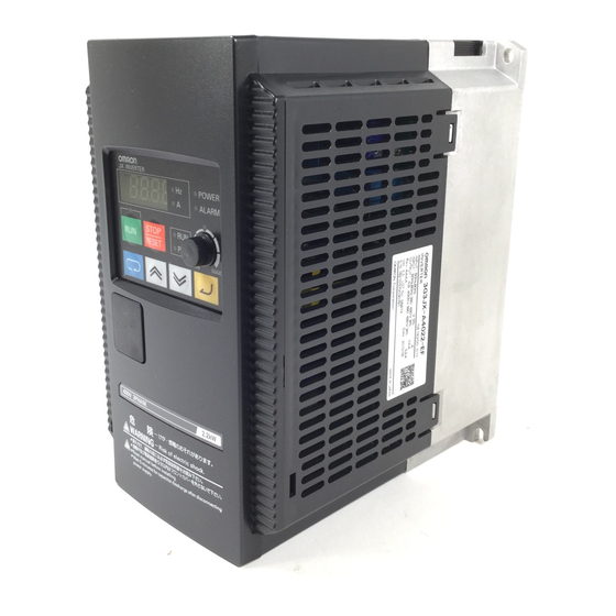
- Page 1 S impl e, Compact Inv erters J X -seri es Replace Guide From 3G3JX to 3G3MX2 □□□□ 3G3MX2- A □□□□ 3G3JX-A I924-E1-01...
- Page 2 Moreover, because OMRON is constantly striving to improve its high-quality products, the information contained in this manual is subject to change without notice. Every precaution has been taken in the preparation of this manual. Nevertheless, OMRON assumes no responsibility for errors or omissions. Neither is any liability assumed for damages resulting...
-
Page 3: Introduction
Introduction This guide provides the reference information for replacement and does not contain safety information and other details that are required for actual use. Thoroughly read and understand the manuals for both the old and new inverters to ensure that the system is used safely. Review the entire contents of these manuals, including all safety precautions, precautions for safe use, and precautions for correct use. -
Page 4: Terms And Conditions Agreement
(a) Exclusive Warranty. Omron’s exclusive warranty is that the Products will be free from defects in materials and workmanship for a period of twelve months from the date of sale by Omron (or such other period expressed in writing by Omron). Omron disclaims all other warranties, express or implied. - Page 5 Performance Data. Data presented in Omron Company websites, catalogs and other materials is provided as a guide for the user in determining suitability and does not constitute a warranty. It may represent the result of Omron’s test conditions, and the user must correlate it to actual application requirements. Actual performance is subject to the Omron’s Warranty and Limitations of Liability.
-
Page 6: Precautions
• When building a system, check the specifications for all devices and equipment that will make up the system and make sure that the OMRON products are used well within their rated specifications and performances. Safety measures, such as safety circuits, must be implemented in order to minimize the risks in the event of a malfunction. -
Page 7: Related Manuals
Related Manuals Please see the manuals below for related product information. Use these manuals for reference. Manual name Cat. No. Model Description 3G3JX Series I558 3G3JX-□□□□□ Describes how to install and wire the inverter, set parameters Compact Simplified needed to operate the inverter, and remedies to be taken and Inverter inspection methods to be used in case that problems occur. -
Page 8: Revision History
Revision History A manual revision code appears as a suffix to the catalog number on the front and back covers of the manual. I924-E1-01 Cat.No. Revision Revision code Date Revised content July 2019 Original production... -
Page 9: Table Of Contents
Index Introduction .............. 3 Intended Audience ............3 Applicable Products ............3 Terms and Conditions Agreement ..........4 Precautions .............. 6 Related Manuals ............7 Revision History ............8 Target model ............10 Precautions for replacement ........... 11 External Dimensions and Mounting dimensions ......12 3.1. -
Page 10: Target Model
1. Target model (1) Replaced (old) model 3G3JX series Compact Simplified Inverter 3G3JX-□□□□□ (2) New model 3G3MX2 Series Type V1 Multi-function Compact Inverter 3G3MX2-□□□□□-V1... -
Page 11: Precautions For Replacement
2. Precautions for replacement (1) There are some differences between 3G3JX and 3G3MX2-V1. Before replacement, refer to not only this guide but also related product user’s manuals. (2) 3G3JX has a 3-phase 400-V class 3.7 kW capacitor model. Please replace with a 3-phase 400-V class 4.0 kW capacitor model. -
Page 12: External Dimensions And Mounting Dimensions
3. External Dimensions and Mounting dimensions The following tables show external dimensions and mounting dimensions of 3G3JX and 3G3MX2-V1. You can install multiple 3G3MX2-V1s side by side like 3G3JXs. Note that the external dimensions of 3G3MX2-V1 are smaller than or equal to 3G3JX but the depths (D) of all 3G3MX2-V1 models and the heights (H) of over 5.5 kW models of 3G3MX2-V1 are larger than 3G3JX. -
Page 13: External Dimensions
AE015 159.4 Φ5 AB015-V1 170.5 Φ4.5 AE022 159.4 Φ5 AB022-V1 170.5 Φ4.5 *1. When using 3G3JX-AE□ with 3-phase 200 V input, select from 3G3MX2-V1 3-phase 200 V input specifications. *2. When using 3G3JX-AE□ with single-phase 200 V input, select from 3G3MX2-V1 single-phase 200 V input specifications. - Page 14 3G3JX Series 3G3MX2-V1 Series Model Model D [mm] D1 [mm] D2 [mm] D [mm] D1 [mm] 3G3JX- 3G3MX2- A4004 A4004-V1 143.5 130.5 AE007 A2015-V1 A2015 A2022-V1 A2022 A4007-V1 A4007 A4015-V1 170.5 A4015 157.5 A4022-V1 A4022 AB007-V1 AE015 AB015-V1 AE022 AB022-V1...
- Page 15 3G3JX Series 3G3MX2-V1 Series Model Model 3G3JX- 3G3MX2- A2037 A2037-V1 A4037 A4040-V1...
- Page 16 3G3JX Series 3G3MX2-V1 Series Model Model 3G3JX- 3G3MX2- A2055 A2055-V1 A2075 A2075-V1 A4055 A4055-V1 A4075 A4075-V1...
-
Page 17: Arrangement And Function Of Terminal Block
4. Arrangement and Function of Terminal Block There are some difference of Arrangement and Function of Terminal Block between 3G3JX and 3G3MX2-V1. Before setting, to refer this section. Refer to related product user’s manual. 4.1. Control Circuit Terminal Block 3G3JX 3G3MX2-V1 Remarks Terminal... - Page 18 Current frequency Current frequency Frequency reference input reference signal reference signal (Analog current input) Frequency reference Input signal common In 3G3MX2-V1, common common terminal for the internal power supply, digital input, and analog I/O terminals. Multi-function Multi-function This terminal is automatically output terminal output terminal set to P1 (EDM: Safety...
-
Page 19: Functional Difference
5. Functional difference 5.1. Dual duty rating 3G3MX2-V1 supports the dual duty rating: heavy load (CT) and light load (VT) that allows the inverter to drive a motor whose capacity is one size large. Heavy load (CT) is used in this guide. Heavy load (CT) This mode is for general loads that temporarily exceed the rated torque during acceleration and deceleration. -
Page 20: Parameter List
6. Parameter List 6.1. The difference of parameter arrangement, parameter name and default value There are some difference of Parameter name, settings, number, date range and arrangement between 3G3JX and 3G3MX2-V1. Before setting, to refer this section. Refer to related product user’s manuals. -
Page 21: The Difference Of Multi-Function Input Settings
6.2. The difference of multi-function Input Settings There are some difference of multi-function Input Settings between 3G3JX and 3G3MX2-V1. Before setting, to refer the following list. Refer to related product user’s manuals. 3G3JX 3G3MX2-V1 Data No. Code Function name Code Function name forward Forward... -
Page 22: The Difference Of Multi-Function Output Settings
F-TM forced terminal block F-TM Forced terminal block Torque command input ready function permission SP-SET special 2nd function Integrated power clear emergency shutoff No allocation function 6.3. The difference of multi-function Output Settings There are some difference of multi-function Output Settings between 3G3JX and 3G3MX2-V1. Before setting, to refer the following table. -
Page 23: Modbus Communication Data Correspondence List
7. Modbus Communication Data Correspondence List There are some difference of Modbus Communication Coil Number and Register Number between 3G3JX and 3G3MX2-V1. Adjust the program of the host controller after referring to the table below and check the operation. In addition, be sure to refer to the user's manuals for each inverter. 7.1. -
Page 24: Register Number
7.2. Register Number In 3G3MX2-V1, (Register address)=(Register number)-1 。 3G3JX 3G3MX2-V1 Function name Register Parameter Data Register Parameter Data Monitor or setting data Monitor or setting data resolution resolution Frequency reference 0001h F001(HIGH) 0002h 0 ~ 4000 0.1[Hz] 0 to Maximum frequency 0.01[Hz] (Enable when A001 = 03) 0002h... - Page 25 00: Digital Operator (volume) 00: Volume 01: Terminal 01: Control circuit terminal block 02: Digital Operator (F001) (Analog input) 03: ModBus communication 02: Digital Operator Frequency reference 1019h A001 10: Frequency operation result 1201h A001 03: Modbus communication selection 04: Option 06: Pulse train frequency 07: DriveProgramming 10: Operation function output...
- Page 26 Output voltage gain 104Eh A045 123Fh A045 20 ~ 100 1[%] 20~100 1[%] 2nd output voltage gain 1514h A245 223Fh A245 00: Disabled 00: Disabled DC injection braking 01: Enabled 1051h A051 01: Enabled during stop 1245h A051 selection 02: Enabled (Operates only at set 02: Output frequency<A052 DB frequency) DC injection braking...
- Page 27 00: Start frequency A101 00: FI Start Frequency (A101) FI start selection 1085h A105 1287h A105 01: 0 Hz 01: 0 Hz 00: Digital Operator (F001) 00: Digital Operator (A020/A220) Operation frequency input A 01: Digital Operator (volume) 01: Volume 108Eh A141 12AFh...
- Page 28 1~999 (In the high-frequency Starting frequency 10D1h b082 5 ~ 99 0.1[Hz] 1355h b082 0.01[Hz] mode︓~10000) Carrier frequency 10D2h b083 20 ~ 120 0.1[kHz] 1356h b083 20~150 (100) 0.1[kHz] 00: Clears the trip monitor 00: Initialization disabled 01: Initializes data 01: Clearing fault monitor 02: Clears the trip monitor and 02: Initialize data...
- Page 29 00: FW (Forward) 00: FW 01: RV (Reverse) 01: RV 02: CF1 (Multi-step speed setting 02: CF1 Multi-function input 1 1103h C001 1401h C001 binary 1) 03: CF2 selection 03: CF2 (Multi-step speed setting 04:CF3 binary 2) 05: CF4 04: CF3 (Multi-step speed setting 06: JG binary 3) 07: DB...
- Page 30 00: RUN 00: RUN (During RUN) 01: FA1 01: FA1 (Constant speed arrival 02: FA2 signal) 03: OL 02: FA2 (Set frequency exceeded 04: OD signal) 05: AL 03: OL (Overload warning) 06: Dc 04: OD (Excessive PID deviation) 07: FBV 05: AL (Alarm signal) 08: NDc 06: FA3 (Set-frequency only signal)
- Page 31 03(2400bps)/ 04(4800bps)/ Communication speed 05(9600bps)/ 06(19.2kbps)/ selection 1138h C071 144Bh C071 07(38.4kbps)/ 08(57.6kbps)/ (Baud rate selection) 09(76.8kbps)/ 10(115.2kbps) Communication station No. 1139h C072 144Ch C072 1~247 Communication parity 113Bh C074 144Eh C074 00: No/ 01: Even/ 02: Odd selection Communication stop bit Do not change through ModBus 1: 1 bit 113Ch...
- Page 32 Note: Do not use this document to operate the Unit. 2019 I924-E1-01 0919 (0919)