Omron 3G3MX2 Quick Start Manual
Born to drive machines; 200 v class three-phase input 0.1 to 15 kw; 200 v class single-phase input 0.1 to 2.2 kw; 400 v class three-phase input 0.4 to 15 kw
Hide thumbs
Also See for 3G3MX2:
- User manual (440 pages) ,
- Connection manual (34 pages) ,
- Network connection manual (66 pages)
Table of Contents
Advertisement
Advertisement
Table of Contents

Related Manuals for Omron 3G3MX2


Summary of Contents for Omron 3G3MX2
- Page 1 At the end of this document you will find links to products related to this catalog. You can go directly to our shop by clicking HERE. HERE...
-
Page 2: Quick Start Guide
Cat. No. I129E-EN-02 Born to drive machines Model: 3G3MX2 200 V Class Three-Phase Input 0.1 to 15 kW 200 V Class Single-Phase Input 0.1 to 2.2 kW 400 V Class Three-Phase Input 0.4 to 15 kW QUICK START GUIDE... -
Page 4: Table Of Contents
MX2 Quick Start Guide 1 SPECIFICATIONS ................3 1.1 Upon receipt ......................3 1.2 Technical specification ................... 4 1.3 Power ratings ......................4 2 INSTALLATION ..................6 2.1 Wiring sizes and protection ..................6 2.2 External dimensions for installation (IP20 & IP54) .......... - Page 5 MX2 Quick Start Guide...
-
Page 6: Specifications
3 x 400 V AX-FIM3014-RE/SE 3G3MX2-A4040-E 3G3MX2-D4040-EC 11.1 3G3MX2-A4055-E 3G3MX2-D4055-EC 14.8 17.5 AX-FIM3030-RE/SE 3G3MX2-A4075-E 3G3MX2-D4075-EC 18.0 23.0 3G3MX2-A4110-E 3G3MX2-D4110-EC 24.0 31.0 AX-FIM3050-RE/SE 3G3MX2-A4150-E 3G3MX2-D4150-EC 31.0 18.5 38.0 * 3G3MX2-D types include a built in EMC filter MX2 Quick Start Guide... -
Page 7: Technical Specification
Stall prevention during acceleration/deceleration and constant speed Stall prevention level Detection at power-on Ground fault IP20, Varnish coating on PCB & IP54 (For 3G3MX2-D@ type) Degree of protection 90% RH or less (without condensation) Ambient humidity -20 ºC..+65 ºC (short-term temperature during transportation) Storage temperature -10°C to 50°C (Output current derating could be necessary above 40ºC or depending on installation conditions) - Page 8 SPECIFICATIONS Item Three-phase 200V class Specifications 3G3MX2 inverters, 200 V models A2001 A2002 A2004 A2007 A2015 A2022 A2037 A2055 A2075 A2110 A2150 0.75 18.5 0.75 Applicable motor size 10.3 13.8 19.3 23.9 200 V Rated 11.4 16.2 20.7 capacity (kVA) 12.4...
-
Page 9: Installation
Applicable equipment (KW) Inverter Model Fuse Terminal Tighttening Signal Lines Power Lines (mm screw Toque (N/m) (UL-rated, class J, 600 V) 3G3MX2-AB001 3G3MX2-AB002 AWG16 / 1.3 mm² 10 A 0.55 3G3MX2-AB004 0.75 3G3MX2-AB007 AWG12 / 3.3 mm² 15 A 3G3MX2-AB015 20 A AWG10 / 5.3 mm²... - Page 10 INSTALLATION 2-Ø4.5 2- Ø 7 8.8.8.8. 8.8.8.8. Power Type W(mm) H (mm) D (mm) D1(mm) 3x 200 V 3G3MX2-A2037 170,5 3x 400 V 3G3MX2-A4040 Power Type W(mm) H (mm) D (mm) D1(mm) 3x 200 V 3G3MX2-A2110 Ø 3G3MX2-A4110 3x 400 V 3G3MX2-A4150 2-Ø7...
- Page 11 299.5 279.5 298.9 317.7 292.7 378.8 Figure 3 Figure 4 376.2 18.7 320.53 299.5 334.7 Figure 1 Figure 2 Figure 3 Figure 4 3G3MX2-DB001-E 3G3MX2-DB001-EC 3G3MX2-D2055-EC 3G3MX2-D2110-EC 3G3MX2-DB002-E 3G3MX2-DB002-EC 3G3MX2-D2075-EC 3G3MX2-D2150-EC 3G3MX2-DB004-E 3G3MX2-DB004-EC 3G3MX2-D4055-EC 3G3MX2-D4110-EC 3G3MX2-D2001-E 3G3MX2-DB007-EC 3G3MX2-D4075-EC 3G3MX2-D4150-EC 3G3MX2-D2002-E...
-
Page 12: Installation Environment Clearance
INSTALLATION Chassis ground of mounting plate Chassis ground of EMC filter Power input to EMC filter DIN rail for mounting options Bracket with EMC filter Fuse for cooling fan MX2 inverter Cooling fan Dust filter Wiring acces hole Mounting plate Air outlet Front cover Window for MX2... -
Page 13: Wiring Overview
MX2 Quick Start Guide 2.4 Wiring overview Shielded motor cable Breaker, MCCB Output to minimize emitted EMC AC Reactor or GFI, dV/dt Groudn both ends Fuses (T1) (L1 ) Motor Power source, (T2) 3-phase or 1-phase, per (L2 ) inverter model (T3) N (L3 ) PD/+1... -
Page 14: Power Wiring
For connection of external regeneration braking unit +, - Regeneration braking unit Earth Earthing terminal. Terminals arrangment Applicable models 3G3MX2-AB001 to AB022 3G3MX2-A2001 to A2037 3G3MX2-A4004 to A4040 3G3MX2-A2040 to A2150 3G3MX2-A4055 to A4150 2.6 Control wiring RS485 Logic inputs comm. -
Page 15: Screwless Terminals Connection
MX2 Quick Start Guide Type Terminal Name Purpose Details Electrical specifications +24 V for logic inputs 24VDC power supply for the DI Max 100mA including DI (5mA each) When source logic is selected, it becomes the common point of input (do not short to terminal L) Intelligent input common This terminal is used as the common terminal of the DI. -
Page 16: Digital Inputs Sink/Source (Npn/Pnp) Settings
INSTALLATION 2.8 Digital inputs SINK/SOURCE (NPN/PNP) settings Sinking internal supply Sinking external supply (for NPN outputs) (for NPN outputs Short-circuit 24 V DC 24 V DC DC24V Output unit etc. Output unit etc. Inverter Inverter Sourcing internal supply Sourcing external supply (for PNP outputs) (for PNP outputs 24 V DC... -
Page 17: Programming Mx2
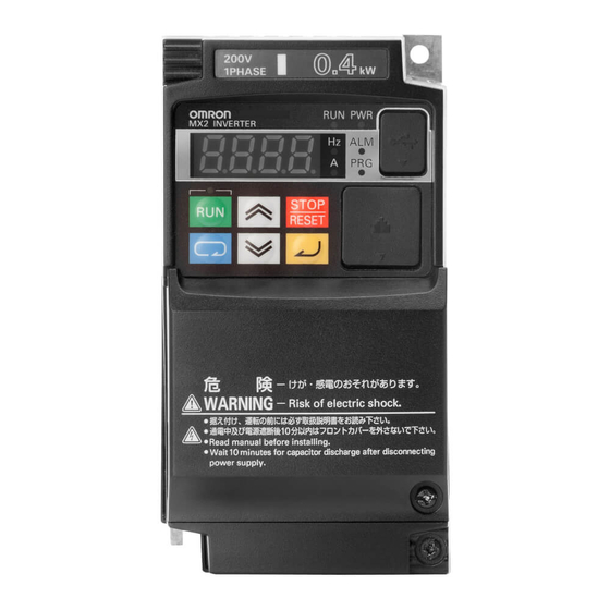
MX2 Quick Start Guide 3 PROGRAMMING MX2 3.1 Digital operator The display is used in programming the inverter's parameters, as well as monitoring specific parameter values during operation (4) RUN LED (1) POWER LED (5) Monitor LED [Hz] (2) ALARM LED (6) Monitor LED [A] (3) Program LED (15) USB connector... -
Page 18: Keypad Navigation
PROGRAMMING MX2 3.2 Keypad navigation Func. code display : Moves to data display Group "d" Func. code display D001 0.00 D002 Func. code display : Jumps to the next group d104 Group "F" Func. code display Save F001 50.00 F002 50.01 F004 Data display... -
Page 19: Inverter Modes
MX2 Quick Start Guide The following display appears for a few seconds, and initialization is completed with d001 displayed Display during initialization 5 HC Initialization of trip history Initialization 5 00 Initialization for area A mode 5 01 Initialization for area B The left digit rotates during initialization d001 Blinking alternately... -
Page 20: Basic Settings
PROGRAMMING MX2 This table shows the parameters that change with the dual rating selectiong is modified Name Func. code Range initial data Range initial data V/f characteristic curve A044 00: Const. torque 00: Const. tq. 00: Const. torque 00: Const. tq. 01: Reduced torque 01: Reduced tq. -
Page 21: Auto Tuning (Slv Mode)
MX2 Quick Start Guide At this point the inverter is ready to run the motor for the first time, but first review this check-list: Verify the power LED is ON. If not, check the power connections. Verify the PRG LED is OFF. If it is ON, review the instructions above. Make sure the motor is disconnected from any mechanical load. - Page 22 PROGRAMMING MX2 Next diagram shows the auto-tuning procedure with motor rotation Step 1: Set motor size and Step 2:Set base freq. and Step 3: Enable auto-tuning motor poles AVR voltage H001 H003 A003 Base freq. Motor size H004 A082 Motor poles AVR voltage Result is displayed Auto-tuning starts...
-
Page 23: Ramps Adjustment
MX2 Quick Start Guide 3.7 Ramps adjustment The basic frequency (speed) profile is defined by parameters con- Output tained in the "F" Group as shown to the right. The set running fre- frequency F002 F003 quency is in Hz, but acceleration and deceleration are specified in the time duration of the ramp (from zero to maximum frequency, A004 or from maximum frequency to zero). -
Page 24: Dc Braking
PROGRAMMING MX2 3.8 DC Braking The DC braking feature can provide additional stopping torque during deceleration or before acceleration and is particulary use- ful at low speeds when normal deceleration torque is minimal. This function injects a DC voltage into the motor windings which generates a DC current that force the motor to stop. -
Page 25: V/F Curve
MX2 Quick Start Guide DC braking at startup is also possible by independent setup of parameters A057 and A058. This is useful in aplications were load should be totally stopped before starting the movement. Parameter Parameter Name Description A051 DC braking enable Three options;... -
Page 26: Torque Boost Function
PROGRAMMING MX2 This table shows the details about the Free V/F control Parameter Parameter Name Diagram Range b100 Free-setting V/F freq(1) 0 to b102(Hz) Output voltage (V) b101 Free-setting V/F volt (1) 0.0 to 800.0(V) b102 Free-setting V/F freq(2) b100 to b104(Hz) b113 b103 Free-setting V/F volt (2) -
Page 27: Analog Inputs
MX2 Quick Start Guide 3.11 Analog inputs MX2 provides two analog inputs, the input terminal group includes the [L], [OI], AM H [O], and [H] terminals on the control connector, which provide for Voltage [O] or +V Ref. Current [OI] input. All analog input signals must use the analog ground [L]. Voltage input If you use either the voltage or current analog input, you must select one of them Current input... -
Page 28: Digital Inputs
PROGRAMMING MX2 3.12 Digital inputs The function codes in the following table let you assign between a wide range of functions to any of the seven logic inputs for the MX2 inverter. The functions C001 through C007 configure the terminals [1] through [7] respectively. The "value" of these partic- ular parameters is not a scalar value, but it is a discrete number that selects one option from many available options. - Page 29 MX2 Quick Start Guide Input Function Summary Table Option Terminal Function Name Description Code Symbol Torque Limit Selection Setting of b040 is enabled Max. torque is limited with 200% TRQ1 Torque limit switch 1 Torque limit related parameters of Powering/regen, and FW/RV modes are selected by the combinations of these inputs.
-
Page 30: Digital Outputs
PROGRAMMING MX2 Parameter Parameter name Description C011 Input [1] active state Select logic conversion, two option codes: 00... normally open [NO] C012 Input [2] active state 01... normally closed [NC] C013 Input [3] active state C014 Input [4] active state C015 Input [5] active state C016... - Page 31 MX2 Quick Start Guide Input Function Summary Table Option Terminal Function Name Description Code Symbol PID Second Stage Output Transitions to ON when the inverter is in RUN Mode and the PID Process Vari- able (PV) is less than the Feedback Low Limit (C053) Transitions to OFF when the PID Process Variable (PV) exceeds the PID High Limit (C052), and transitions to OFF when the inverter goes from Run Mode to Stop Mode...
-
Page 32: Pulse Input
PROGRAMMING MX2 3.14 Pulse input Pulse train input in terminal EA could be used as frequency refer- ence, PID input, encoder feedback for position control and also as an input for Drive Programming. The maximum frequency for this pulse input is 32KHz and the selection is done by parameter P003. Encoder feedback setting is set in parameter P004, but please Encoder 7/EB... -
Page 33: Analogue And Pulse Outputs
MX2 Quick Start Guide 3.15 Analogue and pulse outputs Several monitors are available through the pulse output [EO] or the analogue output [AM]. Parameter Parameter name Description C027 [EO] terminal selection (Pulse/PWM 00... Output frequency (PWM) output) 01... Output current (PWM) 02... -
Page 34: Torque Control
PROGRAMMING MX2 Parameter Parameter name Description b022 Torque limit 2 (rev/regen.) Torque limit level in reverse regen. quadrant, range is 0 to 200% / no(disabled) b043 Torque limit 3 (rev/power) Torque limit level in reverse powering quadrant, range is 0 to 200% / no(disabled) b044 Torque limit 4 (fwd/regen.) Torque limit level in forward regen. -
Page 35: Carrier Frequency (Pwm)
MX2 Quick Start Guide b013 could be used to match the torque characteristic with the load. Output current on the winding is used for this calculation as is proportional to the torque generated by the motor. That’s why the current level has to be set in parameter b012 with a range that goes from 20 to 100% of the inverter rated current. -
Page 36: Pid Function
PROGRAMMING MX2 3.20 PID Function When enabled, the built-in PID loop calculates an ideal inverter output value that cause the loop feedback process variable (PV) to move closer to the set point value (SP). The frequency command is used as SP and the PID loop algorithm will read the analog input for the process variable and calculate the proper inverter output to reach it. -
Page 37: Overvoltage Protection
MX2 Quick Start Guide Over-current Trip Suppression function monitors the motor current OC LAD STOP = Enabled B027 and actively changes the output frequency profile to keep the motor cur- Motor Approx. 150% of the inverter rent below 150% of the motor rated current. Basically the acceleration current rated current ramp is at stopped above this current and it only restarts when the cur-... -
Page 38: Controlled Stop At Power Loss
PARAMETER LIST 3.23 Controlled stop at power loss This function is intended to achieve a controlled stop and avoid free-running of the motor when power is lost during run mode. Inverter controls the internal DC bus voltage while decelerating the motor using the regenerative energy to keep the DC bus at a level that allows to reduce the motor speed and avoid a long coasting time. -
Page 39: Parameter Group A
MX2 Quick Start Guide Function code Function name Monitoring and setting items Units Modbus Register No. d010 Torque bias monitor -200 to +200 1 [%] 100Eh d012 Torque monitor -200 to +200 1 [%] 1010h d013 Output voltage monitor 0 to 6000 0.1 [V] 1011h d014... - Page 40 PARAMETER LIST Function code Function name Monitoring and setting items Units Modbus Default mode Register edit Nº A022 (32-bits) Multi-speed freq. 2 0 or "start frequency" to "maximum frequency" 0.01 [Hz] 121Ah 0.00 121Bh A023 (32-bits) Multi-speed freq. 3 0 or "start frequency"...
- Page 41 MX2 Quick Start Guide Function code Function name Monitoring and setting items Units Modbus Default mode Register edit Nº A071 PID Function Enable 00 (disabling), 01 (enabling), – 125Fh 02 (enabling inverted-data output) A072 PID proportional gain 0 to 2500 0.10 1260h 1.00...
-
Page 42: Parameter Group B
PARAMETER LIST 4.3 Parameter group B Function code Function name Monitoring and setting items Units Modbus Default mode Register edit b001 Restart mode on power failure/ under-voltage trip 00 (tripping), 01 (starting with 0 Hz), 02 (start- – 1301h ing with matching frequency), 03 (tripping after decel- eration and stopping with matching frequency), 04 (restarting with active matching frequency) - Page 43 MX2 Quick Start Guide Function code Function name Monitoring and setting items Units Modbus Default mode Register edit b054 Initial freq. drop of ctrl. decel. 0 to 1000 0.01 [Hz] 1339h 0.00 b060 Maximum-limit level of window comparators O 0.
-
Page 44: Parameter Group C
PARAMETER LIST 4.4 Parameter group C Function code Function name Monitoring and setting items Units Modbus Default mode Register edit C001 Input [1] function Check I/O optiosn on page – 1401h 00 (FW) C002 Input [2] function – 1402h 01 (RV) ... -
Page 45: Parameter Group H
MX2 Quick Start Guide Function code Function name Monitoring and setting items Units Modbus Default mode Register edit C102 Reset mode selection 00 (resetting the trip when RS is on), 01 (resetting the – 146Ah trip when RS is off), 02 (enabling resetting only upon tripping [resetting when RS is on]), 03(resetting only trip) ... -
Page 46: Parameter Group P
PARAMETER LIST Function code Function name Monitoring and setting items Units Modbus Default mode Register edit H105 PM motor rated current Set a level between 20% and 100% for the rated inverter 0.01 [A] 1574h current 0.001 to 65.535 ... - Page 47 MX2 Quick Start Guide Function code Function name Monitoring and setting items Units Modbus Default mode Register edit P057 Pulse train frequency bias -100 to +100 1 [%] 163Bh P058 Pulse train frequency limit 0 to 100 1 [%] 163Ch ...
-
Page 48: Parameter Group F
PARAMETER LIST Function code Function name Monitoring and setting items Units Modbus Default mode Register edit P161 Option I/F command register to write 2 0000 to FFFF – 16A3h 0000 P162 Option I/F command register to write 3 0000 to FFFF –... - Page 49 OmRON EUROPE B.V. Wegalaan 67-69, NL-2132 JD, Hoofddorp, The Netherlands. Tel: +31 (0) 23 568 13 00 Fax: +31 (0) 23 568 13 88 industrial.omron.eu Austria France Netherlands Spain Tel: +43 (0) 2236 377 800 Tel: +33 (0) 1 56 63 70 00...
-
Page 50: Product Code
Buy on EAN MX footprint RFI filter, 14A, 200VAC, single phase, for 283819 AX-FIM1014-RE Buy on EAN 0.75KW models 3G3MX2- Frequency converters, MX2 Three Phase, 200-240VAC, 379065 Buy on EAN A2007-E 0.75 / 1.1KW, 5.0 / 6.0A (HD / ND), vector... - Page 51 7.5KW models MX footprint RFI filter, 14A, 400VAC, three phase, 4.0KW 297864 AX-FIM3014-RE Buy on EAN models 3G3MX2- Frequency converters, MX2 Three-phase 380-480VAC, 11 378478 Buy on EAN A4110-E / 15KW, 24 / 31A (HD / ND) vector 3G3MX2-...
- Page 52 MX Inverter drive, 15/18.5KW(HD/ND), 60/69A(HD/ND), 264296 MX2-A2150-E Buy on EAN 200VAC, three phase input, sensorless vector 3G3MX2- Frequency converters, MX2 Three Phase, 380-480VAC, 379073 Buy on EAN A4004-E 0.4 / 0.75KW, 1.8 / 2.1A (HD / ND) vector 3G3MX2- Frequency converters, MX2 Three Phase, 200-240VAC, 15...
- Page 53 3G3MX2- Frequency converters, MX2 Three Phase, 380-480VAC, 354451 Buy on EAN D4040-EC 4.0 / 5.5KW (HD / ND) vector IP54 Custom 3G3MX2- Frequency converters, MX2 Three Phase, 380-480VAC, 354452 Buy on EAN D4055-EC 5.5 / 7.5KW (HD / ND) vector IP54 Custom...