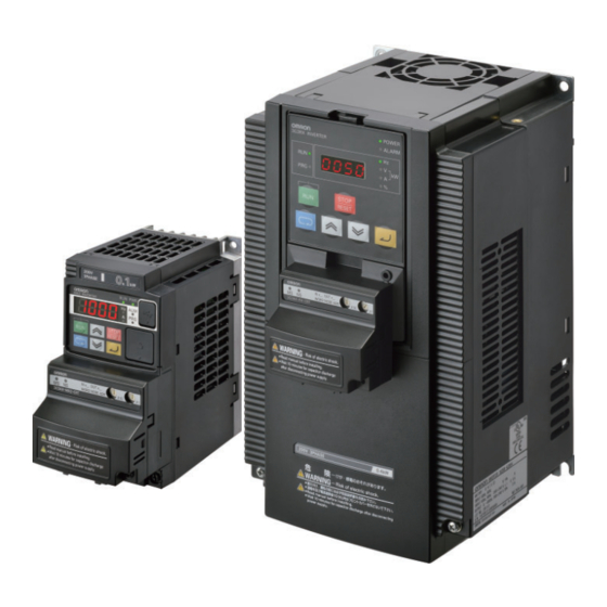
Omron CompoNet MX2 Series User Manual
Inverter, communications unit
Hide thumbs
Also See for CompoNet MX2 Series:
- User manual (620 pages) ,
- Instruction manual (14 pages) ,
- Datasheet (13 pages)

Related Manuals for Omron CompoNet MX2 Series


Summary of Contents for Omron CompoNet MX2 Series
- Page 1 Inverter MX2/RX Series CompoNet Communications Unit User’s Manual 3G3AX-MX2-CRT-E 3G3AX-RX-CRT-E I582-E1-04...
- Page 2 OMRON. No patent liability is assumed with respect to the use of the information contained herein. Moreover, because OMRON is constantly striving to improve its high-quality products, the information contained in this manual is subject to change without notice.
-
Page 3: Introduction
Introduction Introduction Thank you for purchasing a CompoNet Communications Unit (Model: 3G3AX-MX2-CRT-E/ 3G3AX-RX-CRT-E). This User's Manual describes the installation and wiring of the 3G3AX-MX2-CRT-E/3G3AX-RX-CRT-E and parameter setting method which is required for the opera- tion, as well as troubleshooting and inspection methods. Intended Audience This manual is intended for the following personnel, who must also have knowledge of electrical sys- tems (an electrical engineer or the equivalent). -
Page 4: Manual Configuration
Manual Configuration Manual Configuration This User's Manual is compiled section by section for user's convenience as follows. Outline Section 1 Outline This section provides an outline, features, and specifications of the Com- poNet Communications Unit. Section 2 CompoNet Communications Unit This section provides the part names of the CompoNet Communications Mounting and Wiring Unit and mounting/wiring methods. -
Page 5: Manual Structure
Normally, inverter operation can be controlled using the Basic Speed I/O or Extended I/O function with difference icons. included as standard in CompoNet. To set the acceleration/deceleration time, however, you need to use OMRON's unique Extended Speed and Acceleration Control function. This section explains how to configure these three types of Remote I/O. - Page 6 Manual Structure Special Information Special information in this manual is classified as follows: Precautions for Safe Use Precautions on what to do and what not to do to ensure safe usage of the product. Precautions for Correct Use Precautions for Correct Use Precautions on what to do and what not to do to ensure proper operation and performance.
-
Page 7: Sections In This Manual
Sections in this Manual Sections in this Manual Outline CompoNet Communications Unit Mounting and Wiring Network Startup Remote I/O Message Communications Troubleshooting Appendices Index CompoNet Communications Unit User’s Manual (I582-E1) -
Page 8: Table Of Contents
CONTENTS CONTENTS Introduction ......................1 Manual Configuration ....................2 Manual Structure ...................... 3 Sections in this Manual ................... 5 CONTENTS ........................ 6 Read and Understand this Manual ................. 9 Safety Precautions ....................12 Precautions for Safe Use ..................15 Precautions for Correct Use.................. 17 Regulations and Standards ................... -
Page 9: Contents
CONTENTS 2-2-4 Connector Wiring ........................2-15 Section 3 Network Startup Inverter Configuration......................3-2 3-1-1 Basic and Extended Speed I/O Settings..................3-2 3-1-2 Remote I/O Settings Using Torque Reference................3-6 3-1-3 Special I/O and Flexible Format Settings ................... 3-9 3-1-4 Utilizing Multi-function Inputs/Outputs for Host................. 3-12 Network Configuration...................... - Page 10 CONTENTS 5-4-5 Parameter Class/Instance/Attribute ..................5-12 5-4-6 Ladder Programming Example ....................5-13 Parameter Read/Write (Class 65 hex) ................5-14 5-5-1 Supported Service Codes ......................5-14 5-5-2 Supported Instance and Attribute Codes .................. 5-14 Section 6 Troubleshooting Outline of Error Indication ....................6-2 Errors on a Communications Line ..................
-
Page 11: Read And Understand This Manual
OF PROFITS OR COMMERCIAL LOSS IN ANY WAY CONNECTED WITH THE PRODUCTS, WHETHER SUCH CLAIM IS BASED ON CONTRACT, WARRANTY, NEGLIGENCE, OR STRICT LIABILITY. In no event shall the responsibility of OMRON for any act exceed the individual price of the product on which liability is asserted. - Page 12 Application Considerations SUITABILITY FOR USE OMRON shall not be responsible for conformity with any standards, codes, or regulations that apply to the combina- tion of products in the customer's application or use of the products. At the customer's request, OMRON will provide applicable third party certification documents identifying ratings and limitations of use that apply to the products.
- Page 13 Performance data given in this manual is provided as a guide for the user in determining suitability and does not con- stitute a warranty. It may represent the result of OMRON's test conditions, and the users must correlate it to actual application requirements.
-
Page 14: Safety Precautions
Safety Precautions Safety Precautions To ensure that the CompoNet Communications Unit (Model: 3G3AX-MX2-CRT-E/3G3AX-RX-CRT-E) is used safely and correctly, be sure to read this Safety Precautions section and the main text before using the product. Learn all items you should know before use, regarding the equipment as well as required safety infor- mation and precautions. - Page 15 Safety Precautions DANGER Do not attempt to remove the terminal block cover or disconnect and reconnect the CompoNet Communications Unit during power on or within 10 minutes after power off. Doing so may result in severe injury due to electric shock. Security Measures WARNING Anti-virus protection...
- Page 16 Safety Precautions Caution Inverters contain high voltage parts and short-circuits may sometimes cause product damage or property damage. Measures must be taken to prevent chips, lead-wire pieces, or other metal waste from entering the product, for example, by installing a cover. Do not attempt to disassemble, repair, or modify the CompoNet Communications Unit.
-
Page 17: Precautions For Safe Use
Precautions for Safe Use Precautions for Safe Use Installation and Storage Do not store or use the CompoNet Communications Unit in the following environment: • Locations subject to direct sunlight • Locations subject to ambient temperatures outside the range specified in the specifications •... - Page 18 Precautions for Safe Use Maintenance and Inspection • Be sure to confirm safety before conducting maintenance, inspection or parts replacement. • Invalid parameter configuration may result in a communications error, interrupting the communica- tions function of other units. Before participating in the network, make sure that the communications configuration parameters are set properly.
-
Page 19: Precautions For Correct Use
Precautions for Correct Use Precautions for Correct Use Installation Be sure to meet the constraints on the mounting direction of the inverter. Modbus-RTU Communication Mounting the CompoNet Communications Unit disables the Inverter's Modbus-RTU communication capability. Product Disposal Comply with the local ordinance and regulations when disposing of the product. Warning Labels •... - Page 20 Precautions for Correct Use Supported Inverter Versions There is a restriction on the unit version of the inverter that can be used with the CompoNet Communi- cations Unit. Make sure that your inverter's unit version is 1.1 or later. Make sure that your inverter is 3G3RX-V1 series (unit version 2.0 or later). Note The inverter unit version is indicated on the nameplate attached to the inverter.
-
Page 21: Regulations And Standards
Regulations and Standards Regulations and Standards To export (or provide to nonresident aliens) any part of this product that falls under the category of goods (or technologies) for which an export certificate or license is mandatory according to the Foreign Exchange and Foreign Trade Control Law of Japan, an export certificate or license (or service transac- tion approval) according to this law is required. -
Page 22: Trademarks
Trademarks Trademarks • CompoNet is a registered trademark of the Open DeviceNet Vendor Association (ODVA). • Windows is a registered trademark of Microsoft Corporation in the United States and other countries. • Other company names and product names in this document are the trademarks or registered trade- marks of their respective companies. -
Page 23: Items To Check After Unpacking
Items to Check After Unpacking On delivery, be sure to check that the delivered product is what you ordered. In case that you find any problems with the product, immediately contact your nearest local sales representative or OMRON sales office. - Page 24 CompoNet Communications Unit 3G3AX-MX2-CRT-E (For MX2 Series) Manual Thank you for purchasing an OMRON product. Please check that this is the one you intended and read this manual carefully before use. Always keep this manual in a safe and handy place.
-
Page 25: Related Manuals
Related Manuals Related Manuals To operate this CompoNet Communications Unit, you must be familiar with the equipment connected to it. Please refer to the following manuals for information on the related products. Inverter Manuals Model and Name Catalog No. Multi-function Compact Inverter MX2 User's Manual I570 High-function General-purpose Inverter 3G3RX--V1 User's Manual I578... -
Page 26: Revision History
Revision History Revision History The manual revision code is a number appended to the end of the catalog number found in the bottom right-hand corner of the front and back covers. Example I582-E1-04 Cat.No. Revision code Revision Revision Date Revised Content Code January 2012 Original production... -
Page 27: Outline
Outline This section provides an outline, features, and specifications of the CompoNet Com- munications Unit. 1-1 Outline of CompoNet Communications Unit ......1-2 1-2 Overview of CompoNet Communications . -
Page 28: Outline Of Componet Communications Unit
1 Outline Outline of CompoNet Communications Unit The CompoNet Communications Unit (Model:3G3A-MX2-CRT-E) is used in conjunction with a multi-function compact inverter, the MX2-series. On the other hand, the CompoNet Communications Unit (Model:3G3A-RX-CRT-E) is intended for high-function general-purpose inverter, the RX-series. The CompoNet Communications Unit is an interface unit that realizes data communications between an inverter and a CS/CJ-series Programmable Controller. - Page 29 1 Outline Communications with CS/CJ-series A CompoNet communications system can be used in conjunction with a CS/CJ-series programmable controller. You can connect up to 32 inverters to a CompoNet communications system and control them. Precautions for Correct Use Precautions for Correct Use •...
- Page 30 In addition, you can use the Parameter Read/Write message object (Class 64), a unique enhance- ment by OMRON, to read/write the parameter settings and monitor values stored in the inverter. Using the Explicit Message function in conjunction with Remote I/O enables the use of data not allo- cated to Remote I/O because these function can be used independent of each other.
-
Page 31: Overview Of Componet Communications
1 Outline Overview of CompoNet Communications 1-2-1 Functions CompoNet network is a component-level network system between a PLC and on-site I/O devices, which features the ease of operation and installation. The PLC and CompoNet Slave Units cyclically exchange I/O information through a CompoNet Master Unit, and refresh I/O in synchronization with the PLC scan. - Page 32 1 Outline Repeater Units for Greater Flexibility Repeater Units can be used in a network to enable the following network expansions. • Extending the cable length • Increasing the number of nodes • Branching from the trunk line • Changing the type of cable Repeater Units can be used to extend up to two segment layers (called subtrunk lines) from the trunk line.
- Page 33 1 Outline Complete Maintenance Functions with System Monitoring Capability The CompoNet network system is constantly monitored to enable to confirm system safety by quickly isolating errors and checking communications status. CX-Integrator The CX-Integrator provides the following network functionality. • Uploading the network system configuration •...
- Page 34 1 Outline Registration Tables The Registration Table registers each node address and corresponding model of Slave Units, which should participate in the network, from CX-Integrator. This function checks the participating Slave Units and prevents unregistered Slave Units from participating in the network. After the power sup- ply is turned ON, the monitoring time until registered Slave Units participate in the network can also be set.
-
Page 35: Configuration
1 Outline 1-2-3 Configuration Configuration (Example) : Repeater Unit CompoNet Master Unit : Terminating Resistor : T-branch Branch Line Slave Trunk Line Subtrunk Line Terminating Resistor Repeater Terminating Unit Branch Line Repeater Unit Resistor Repeater Subtrunk Line Unit Slave Branch Line Branch Line Repeater Unit Subtrunk... -
Page 36: Maximum Number Of Inverter Connections
1 Outline 1-2-4 Maximum Number of Inverter Connections The following list shows the maximum number of inverter connections in each communications mode. Max. No. of I/O Memory Area Allo- Inverter Connec- cation Size Node Occu- tions Addresses of Control pied Unit Communica- Mode Allocation... -
Page 37: Specifications
1 Outline Specifications CompoNet Communications Unit Item Specification Installation Unit type MX2-series CompoNet Communications Unit Model 3G3AX-MX2-CRT-E Dimensions (W x H x D) 68 x 60 x 45 mm Weight 100 g or less (Shipping weight: Approx. 170 g) Installation Unit type RX-series CompoNet Communications Unit... - Page 38 1 Outline Item Specification CompoNet Default connection path Supported, set with inverter parameter P046 Configura- Supported assemblies Basic Speed I/O (Output assembly 20, Input assembly 70) tion Extended Speed I/O (21, 71) Extended Speed and Torque Control (123, 173) Special I/O (100, 150) Extended Control I/O (101, 151) Extended Control I/O and Multi function I/O Monitor (101, 153) Flexible Format (139, 159)
- Page 39 1 Outline Inverter Model Product Name ID Code Name of EDS File 3G3MX2-A4075 3G3AX-MX2-CRT-A4075 1872 3G3AX-MX2-CRT-A4075.eds 3G3MX2-A4110 3G3AX-MX2-CRT-A4110 1873 3G3AX-MX2-CRT-A4110.eds 3G3MX2-A4150 3G3AX-MX2-CRT-A4150 1874 3G3AX-MX2-CRT-A4150.eds RX-series Device List Inverter Model Product Name ID Code Name of EDS File 3G3RX-A2004 3G3AX-RX-CRT-A2004-V1 2095 3G3AX-RX-CRT-A2004-V1.eds 3G3RX-A2007...
- Page 40 1 Outline Dimensions of CompoNet Communications Unit Dimensions of CompoNet Communications Unit (when Mounted on MX2-series Inverter) Item Dimension Item Dimension Item Dimension 60.0 mm 9.4 mm 31.3 mm 60.7 mm 52.6 mm 44.8 mm 67.6 mm 26.4 mm 28.4 mm *1 Dimension d1 gives the increase in the depth of the MX2-series Inverter when the CompoNet Communications Unit is mounted.
-
Page 41: Restrictions On Use
1 Outline Restrictions on Use 1-4-1 Supported Inverters The CompoNet Communications Unit (Model: 3G3AX-MX2-CRT-E) supports the MX2-series Inverters with Ver. 1.1 or later. The MX2-series Inverter version can be identified by the inverter type label. Please check that your inverter type label indicates Ver. 1.1 or later in the position displayed in this illus- tration. -
Page 42: Restrictions
Precautions for Correct Use To edit parameters via network, use the Inverter/Servo support software CX-Drive to establish connection via an OMRON PLC and CompoNet. Restrictions on Editing Device Parameters If you use CX-Integrator to edit device parameters with an EDS file, you cannot edit the second and third control parameters of the inverter. -
Page 43: Componet Communications Unit Mounting And Wiring
CompoNet Communications Unit Mounting and Wiring This section provides the part names of the CompoNet Communications Unit and mounting/wiring methods. 2-1 Name and Setting of Each CompoNet Com- munications Unit Component ........2-2 2-1-1 Name and Setting of Each Component . -
Page 44: Name And Setting Of Each Componet Communications Unit Component
2 CompoNet Communications Unit Mounting and Wiring Name and Setting of Each CompoNet Communications Unit Component 2-1-1 Name and Setting of Each Component Rear face A - Inverter connector B - LED indicators (MS, NS) C - Warning label D - CompoNet connector E - Grounding cable F - Housing G - Mounting screw... - Page 45 2 CompoNet Communications Unit Mounting and Wiring A - Inverter connection PCB B - LED indicators (MS, NS) C - Flat cable D - CompoNet connector E - Grounding cable F - Housing • Before use, cut the FG cable into an appropriate length for the distance to the inverter's ground termi- nal and the size of terminal block, and crimp the crimp terminal.
-
Page 46: Led Indicators
2 CompoNet Communications Unit Mounting and Wiring 2-1-2 LED Indicators The LED indicators on the front face indicate the operational mode and status of the CompoNet Com- munications Unit and the network. LED Indicators Indicator Color State Meaning Green Normal operation (Module Status) Unrecoverable fault... -
Page 47: Rotary Switches
2 CompoNet Communications Unit Mounting and Wiring 2-1-3 Rotary Switches The rotary switches are used to set the node address of the CompoNet Communications Unit. Set the node address as a decimal number between 0 and 63. Set the 10s digit on the left rotary switch and set the 1s digit on the right rotary switch. The setting of the switches is updated when the Unit power supply is cycled. -
Page 48: Installation
2 CompoNet Communications Unit Mounting and Wiring Installation DANGER Do not attempt to remove the terminal block cover or disconnect and reconnect the CompoNet Communications Unit during power on or within 10 minutes after power off. Doing so may result in severe injury due to electric shock. Caution Inverters contain high voltage parts and short-circuits may sometimes cause product damage or property damage. -
Page 49: Mounting Procedure Of Componet Communications Unit On Mx2-Series Inverter
2 CompoNet Communications Unit Mounting and Wiring • If the CompoNet Communications Unit is used in the following locations, provide sufficient shielding measures. Using the CompoNet Communications Unit in any of these locations may result in equip- ment damage. Locations subject to static electricity or other forms of noise Locations subject to strong electromagnetic fields Locations close to power lines •... - Page 50 2 CompoNet Communications Unit Mounting and Wiring Connect the CompoNet Communications Unit's grounding cable to inverter with a mounting screw. 1-phase 200 V 0.1 to 2.2 kW 3-phase 200 V 5.5 to 15 kW 3-phase 200 V 0.1 to 3.7 kW 3-phase 400 V 5.5 to 15 kW 3-phase 400 V 0.4 to 4.0 kW If removed in Step 2, reinstall the terminal cover...
- Page 51 2 CompoNet Communications Unit Mounting and Wiring Press down on the indicated corner of the Compo- Net Communications Unit housing to ensure proper connection of the CompoNet Communications Unit connector. Check that there is no gap between the top edges of the CompoNet Communications Unit and the inverter casing.
-
Page 52: Mounting Procedure Of Compenet Communications Unit On Rx-Series Inverter
2 CompoNet Communications Unit Mounting and Wiring Precautions for Correct Use Precautions for Correct Use Some inverter models do not include a screw for the grounding cable. Please supply the rec- ommended screw, lock-washer, and washer to attach the grounding cable. •... - Page 53 2 CompoNet Communications Unit Mounting and Wiring Cut out the two plastic break-outs from the front cover. Make sure no sharp edges remain. Reinstall the front cover and tighten the screws. Connect the connector of inverter connection PCB of CompoNet Communications Unit to the connector of inverter.
- Page 54 2 CompoNet Communications Unit Mounting and Wiring Precautions for Correct Use Precautions for Correct Use The inverter connector is fixed with a sufficient binding force against vibration. It is not neces- sary to secure the inverter connection PCB with screws. Fold the flat cable (B) into the middle of the Unit so that the flat cable will not be pinched between the CompoNet Communications Unit and the front cover of inverter.
- Page 55 2 CompoNet Communications Unit Mounting and Wiring Insert the CompoNet Communications Unit fixation screw into the hole shown in the right figure, and tighten it to fix the Unit. Be careful not to overtighten the screw. Connect the grounding cable of the CompoNet Communications Unit to the ground terminal of the inverter.
- Page 56 2 CompoNet Communications Unit Mounting and Wiring Install the Digital Operator on the upper portion of the CompoNet Communications Unit. • Keep the spacer cover you removed in a safe place. If You Use the LCD Digital Operator Connect the Digital Operator via a straight Ethernet cable to the RJ45 connector in the inverter.
-
Page 57: Operating Environment
2 CompoNet Communications Unit Mounting and Wiring When the required inverter parameters are set properly, remove the straight Ethernet cable from the inverter. Additional Information For how to remove the CompoNet Communications Unit, refer to 6-6 Removing CompoNet Communications Unit on page 6-13. 2-2-3 Operating Environment For information on the installation environment, refer to Section 2 Design of the MX2 User's Manual... - Page 58 2 CompoNet Communications Unit Mounting and Wiring 2 - 16 CompoNet Communications Unit User’s Manual (I582-E1)
-
Page 59: Network Startup
Network Startup This section describes inverter parameter settings and CompoNet settings/startup. 3-1 Inverter Configuration ......... . 3-2 3-1-1 Basic and Extended Speed I/O Settings . -
Page 60: Inverter Configuration
Normally, inverter operation can be controlled using the Basic Speed I/O or Extended I/O function included as standard in CompoNet. To set the acceleration/deceleration time, however, you need to use OMRON's unique Extended Speed and Acceleration Control function. This section explains how to configure these three types of Remote I/O. - Page 61 3 Network Startup Complete Parameter Display By default, you cannot view all parameters. To display all parameters, set Display Selection (b037) to 00: Complete display. Parameter No. Function Name Monitor or Data Range b037 Display Selection 00: Complete display 01: Individual display of functions 02: User setting + b037 03: Data comparison display 04: Basic display...
- Page 62 CompoNet Communications Unit, which in turn causes the communication connection to be reset. To prevent the communication connection from being reset when the inverter is reset, OMRON recom- mends the following setting. For details about this parameter, refer to the MX2 User's Manual (Cat. No. I570) or RX User's Manual (Cat.
- Page 63 3 Network Startup Frequency Reference/RUN Command Settings Inverter parameters A001 and A002 set Frequency reference selection and RUN command selection. When P046 is set to 0 (Basic Speed I/O), 1 (Extended Speed I/O), or 7 (Extended Speed and Accelera- tion Control), set these parameters according to the following table. ...
-
Page 64: Remote I/O Settings Using Torque Reference
CompoNet Communications Unit, which in turn causes the communication connection to be reset. To prevent the communication connection from being reset when the inverter is reset, OMRON recom- mends the following setting. For details about this parameter, refer to the MX2 User's Manual (Cat. No. I570) or RX User's Manual (Cat. - Page 65 04: Deceleration stop P048 Operation at Idle Mode Detec- Sets the inverter operation in Network Idle mode. OMRON's tion Setting CompoNet Master Units do not support transition to the Net- work Idle mode and therefore this parameter is not required.
- Page 66 3 Network Startup Frequency Reference/RUN Command Settings Inverter parameters A001 and A002 set Frequency reference selection and RUN command selection. When P046 is set to 2 (Extended Speed and Torque Control), 4 (Extended Control I/O), or 5 (Extended Control I/O and Multi function I/O Monitor), set these parameters according to the following table. ...
-
Page 67: Special I/O And Flexible Format Settings
3 Network Startup Restarting the Inverter Be sure to cycle the power supply of the MX2/RX-series Inverter to enable the changes. Precautions for Correct Use Precautions for Correct Use • Be sure that the POWER LED indicator is not lit when cycling the power supply of the MX2/RX-series Inverter. - Page 68 CompoNet Communications Unit, which in turn causes the communication connection to be reset. To prevent the communication connection from being reset when the inverter is reset, OMRON recom- mends the following setting. For details about this parameter, refer to the MX2 User's Manual (Cat. No. I570) or RX User's Manual (Cat.
- Page 69 3 Network Startup Frequency Reference/RUN Command Settings Inverter parameters A001 and A002 set Frequency reference selection and RUN command selection. When P046 is set to 3: Special I/O or 6: Flexible Format, Modbus communication is used. Set these parameters according to the following table. ...
-
Page 70: Utilizing Multi-Function Inputs/Outputs For Host
3 Network Startup Flexible Format Settings The Flexible Format (Assembly 139/159) gives you the freedom to allocate inverter Modbus registers to Remote I/O devices. A maximum of 8 words can be allocated for input and output. Please refer to 4-4 Special I/O and Flexible Format on page 4-17 for details. Parameter Description Setting... - Page 71 3 Network Startup Multi-function Input Settings Multi-function Input Monitor Settings Parameter Description Setting C001 Multi-function Input 1 Selection no (255): No allocation Set these parameters to use the inverter inputs C002 Multi-function Input 2 Selection as the PLC's inputs. C003 Multi-function Input 3 Selection C004...
-
Page 72: Network Configuration
3 Network Startup Network Configuration CompoNet communications start automatically just by connecting the communications wiring and turn- ing ON the Master Unit (PLC) and inverters, and then the I/O Memory Areas of the CPU Unit and Slave Units start sharing the data. Each Slave Unit is fixedly allocated to the Special I/O Unit allocation relay areas of the CPU Unit in order of node addresses. - Page 73 3 Network Startup Node Addresses of First Allo- Occu- Communications Word Slaves Word Slave Word Slave Bit Slave cation pied Unit Mode No. Connectable per OUT Area IN Area Support Address Master Unit IN8/OUT8 CIO 2000 + Not avail- (10 x Unit (First address (First address able...
-
Page 74: Allocation To Special I/O Unit Allocation Relay Area (Communications Mode No. 0 To 3)
3 Network Startup Output Allocation Relay Area Input Allocation Relay Area Allocation Allocation Allocation Address Relay Relay CIO 2000 32-point Output Unit CIO 2016 – (Not allocatable) [Node Address 0] CIO 2001 CIO 2017 – 8-point Input Unit (Not allocatable) [Node Address 1] CIO 2002 This CompoNet Communica-... -
Page 75: Allocation Using Cx-Integrator (Communication Mode 8)
3 Network Startup 3-2-4 Allocation Using CX-Integrator (Communication Mode 8) At first, set the rotary switch on the front of the CompoNet Master Unit (CS/CJ-series) to 8 and power on the Master Unit. Connect CX-Integrator to the CS/CJ-series and click the Auto Online icon [ ] in the CX-Integrator toolbar to establish Auto Online connection. - Page 76 3 Network Startup In the network configuration window, double-click the Master Unit, or right-click and select [Parameter] - [Edit]. The Master Unit's Parameter dialog is displayed. On the [General] tab of the Parameter Configuration dialog box, select the [Edit Software Setting Table] check box.
- Page 77 3 Network Startup Set the area type, first address, and allocation size for each allocation area. • Area type: In [Area], select the memory type of the CPU Unit. • First address: In [Address], select the first address of the area. •...
-
Page 78: Registration Table Configuration
3 Network Startup Precautions for Correct Use Precautions for Correct Use • Be sure to set the type of Remote I/O at this point. The number of words occupied by the CompoNet Communications Unit varies with the Remote I/O type. Unless the Remote I/O type is set correctly, automatic network configuration cannot be completed successfully. - Page 79 3 Network Startup Power on the inverter(s) first and configure the following settings according to 3-1 Inverter Configuration on page 3-2. • Set the node address. According to Setting Slave Node Addresses on page 3-15, set the rotary switches or CompoNet node address (P190). •...
- Page 80 3 Network Startup In the Network Configuration window, the network configuration transferred to the PC is displayed. In the Network Configuration window, double-click the Master Unit, or right-click and select [Parameter] - [Edit]. The Master Unit's Parameter dialog is displayed. 3 - 22 CompoNet Communications Unit User’s Manual (I582-E1)
- Page 81 3 Network Startup On the [General] tab of the Parameter Configuration dialog box for the Master Unit, select the [Edit Registration Table] check box. When you select the [Registration Table] tab, the Slaves in the Network Configuration window are displayed in the [Unregistered Device List]. Select the Slave you want to register from the [Unregistered Device List] and click the Register [ ] button.
-
Page 82: Editing Parameters In Parameter Dialog With Eds File
3 Network Startup Editing Parameters in Parameter Dialog with EDS File In CompoNet communications, EDS files are used to establish communication connection. EDS files for CompoNet Communications Units are installed with CX-Integrator (Ver. 2.55 or higher). Using a correct EDS file, you can edit inverter parameters in the [Parameter Dialog]. This section describes how to use an EDS file for editing device parameters and the functional restric- tions applied when using it. -
Page 83: Restrictions Of Edit Device Parameters Function With Eds File
3 Network Startup *3 Parameters with dXXX indicate monitor functions. These parameters cause no problem even if detected in the comparison process. 3-3-2 Restrictions of Edit Device Parameters Function with EDS File Each function in the [Parameter Dialog] is accomplished by using the EDS file and Explicit Message functions defined in the CompoNet Communications. - Page 84 3 Network Startup Error contents Detailed Description Reading from a read-pro- When using the Light Load mode, some parameters are write-prohibited or hibit parameter. read-only. Therefore, in the Light Load mode, you cannot use the functions provided in the [Parameter Dialog]. Always use CX-Drive to edit the inverter parameters.
- Page 85 3 Network Startup Restrictions between Parameters Multi-function Input Selection 1 to 8 (C001 to C008) Multi-function Input Selection 1 to 8 (C001 to C008) 1st Frequency Upper Limit (A061) > 1st Maximum Frequency (A004) 1st Frequency Lower Limit (A062) > 1st Maximum Frequency (A004) Output Frequency Setting (F001), >...
-
Page 86: Editing Parameters With Cx-Drive
The Inverter/Servo support tool CX-Drive is the support software to edit inverter parameters. Installing the OMRON CX-One software simultaneously installs CX-Drive onto the PC. CX-Drive enables you to connect your PC to the RJ45 or USB connector of an inverter to directly edit its parameters. - Page 87 3 Network Startup In the New Drive window, select the Drive Type of the inverter and the Option Board Type. In the [Drive Type] section, select the inverter series and click the [Settings] button to the right. In the Drive Type Settings window, select the Installation type/Option, Voltage Class, and Maxi- mum Motor Capacity and, in the Option Board Type section, select CRT (CompoNet Communi- cations Unit).
- Page 88 3 Network Startup Click the [Gateway PLC] tab and select the type of connection between CX-Drive and the CS/CJ-series CPU Unit. Click the [Properties] button and configure the following settings. • Device Type: Select the model of the CPU Unit to which CX-Drive is connected. •...
- Page 89 3 Network Startup Automatically detecting the connected Inverter In this method, you connect CX-Drive to your inverter using the Autodetect function after configuring the [Autodetect Options] in CX-Drive. Follow the steps below. Start CX-Drive and select [Drive] - [Autodetect Options] to open the Options window. On the [Autodetect] tab, in the [Drive Type Selection] section, select [Inverter] by clicking the [Inverter] check box.
- Page 90 3 Network Startup In the Advanced Options: [Via PLC (CompoNet)] window, configure the following two set- tings. • CompoNet node addresses: Select each node address of the CompoNet Master Unit and the inverter (CompoNet Communications Unit). • [Gateway PLC]: Click the [Settings] button in the [Gateway PLC] section and select the Device Type and the Network Type.
-
Page 91: Outline Of Cx-Drive
3 Network Startup 3-4-2 Outline of CX-Drive The Inverter/Servo support tool CX-Drive enables you to edit inverter parameters and monitor the inverter status. This section provides a functional outline of CX-Drive. Screen Structure of CX-Drive The screen structure of CX-Drive is shown below. Registered drive projects are displayed in the workspace. - Page 92 3 Network Startup Editing Device Parameters Using CX-Drive Double-clicking Parameter Editor in the project opens a window in which all inverter parameters are listed (in ascending order). You can edit inverter parameters in this window. To upload/download inverter parameters, use the Transfer buttons in the toolbar. •...
- Page 93 3 Network Startup Status Function of CX-Drive Open the Status folder in the project and double-click the status information. The window corresponding to the selected status information opens. • Digital Inputs: Displays the current ON/OFF status of digital inputs, including the input settings of the connected inverter.
- Page 94 3 Network Startup 3 - 36 CompoNet Communications Unit User’s Manual (I582-E1)
-
Page 95: Remote I/O
Remote I/O This section describes the configuration method and function of Remote I/O (Compo- Net assembly I/O). 4-1 Remote I/O Configuration ........4-2 4-1-1 Remote I/O Types . -
Page 96: Remote I/O Configuration
Remote I/O included as standard for CompoNet communications. This Remote I/O offers general inverter control functions. Extended Speed and Acceleration Con- OMRON's unique Remote I/O not defined in the CompoNet specifica- trol tions. This is the Extended Speed I/O with an additional Acceleration/Decel- eration Time setting function. -
Page 97: Remote I/O Selection
4 Remote I/O 4-1-2 Remote I/O Selection Select and set the appropriate type of Remote I/O for your application in parameter P046. No. of Assembly No. occupied bytes (hex) Parameter Description Setting (No. of words) Output Input Output Input P046 Assembly 00: Basic Speed I/O 4 (2) -
Page 98: Basic And Extended Speed I/O
4 Remote I/O Basic and Extended Speed I/O 4-2-1 Basic Speed I/O (20/70) Basic Speed I/O is a type of Remote I/O included as standard for CompoNet communications. This Remote I/O offers more limited functions than Extended Speed I/O. Basic Remote Output Assembly ID: 20 Dec (14 hex) ... -
Page 99: Extended Speed I/O (21/71)
4 Remote I/O Input Bit/Data Details Name Description Alarm output 0: Normal 1: Fault/Trip During forward 0: During reverse run/Stopping operation 1: During forward run Rotation Speed Monitor If parameter P049 (Number of Poles for Rotation Speed Setting) is set appropri- ately, the rotational speed unit is [min If parameter P049 (Number of Poles for Rotation Speed Setting) is set to 0, the frequency is monitored in units of [0.01 Hz]. - Page 100 4 Remote I/O Standard Remote Input Assembly ID: 71 Dec (47 hex) Input Format (CS/CJ-series ← Inverter) Bit Allocation Word Byte bit 7 bit 6 bit 5 bit 4 bit 3 bit 2 bit 1 bit 0 IRDY Drive Status n + 1 Rotation Speed Monitor (Low byte) Rotation Speed Monitor (High byte)
-
Page 101: Extended Speed And Acceleration Control (110/111)
4 Remote I/O 4-2-3 Extended Speed and Acceleration Control (110/111) Extended Speed and Acceleration Control is OMRON's unique Remote I/O not defined in the Compo- Net specifications. This is the Extended Speed I/O with an additional Acceleration/Deceleration Time setting function. - Page 102 4 Remote I/O Precautions for Safe Use For safety reasons, the FW, RV, and RS command must be output after the cause of fault/trip is removed. Extended Speed and Acceleration Control Assembly ID: 111 Dec (6F hex) Input Format (CS/CJ-series ← Inverter) Bit Allocation Word Byte...
- Page 103 4 Remote I/O Name Description Drive Status Detail 0: Stopping 1: Running 2: Jogging 3: Free running 4: Direct current DC braking 5: Restart (Retry)/Error detection (Deceleration stop) 7: Restart (Retry) in process 8: Waiting for restart (retry) 10: Fault/Trip 11: Undervoltage condition Rotation Speed Monitor If parameter P049 (Number of Poles for Rotation Speed Setting) is set appropri-...
-
Page 104: Remote I/O With Torque Reference Support
4 Remote I/O Remote I/O with Torque Reference Support 4-3-1 Torque Control Configuration The type of Remote I/O described in this section provides the torque reference for torque control func- tion, in addition to normal inverter speed control. The Remote I/O functions described here can be used without the use of torque control. In this case, the input/output function related to torque control is disabled. -
Page 105: Extended Speed And Torque Control (123/173)
4 Remote I/O 4-3-2 Extended Speed and Torque Control (123/173) Extended Speed and Torque Control is OMRON's unique Remote I/O not defined in the CompoNet specifications. This is the Extended Speed I/O with an additional Torque Reference function. Extended Speed and Torque Control Output Assembly ID: 123 Dec (7B hex) ... - Page 106 4 Remote I/O Extended Speed and Torque Control Input Assembly ID: 173 Dec (AD hex) Input Format (CS1/CJ1-series ← Inverter) Bit Allocation Word Byte bit 7 bit 6 bit 5 bit 4 bit 3 bit 2 bit 1 bit 0 IRDY Drive Status n + 1...
-
Page 107: Extended Control I/O (101/151/153)
4-3-3 Extended Control I/O (101/151/153) Extended Control I/O is OMRON's unique Remote I/O not defined in the CompoNet specifications. This type of Remote I/O is optimized for the input/output function of inverters, allowing you to select each input/output function by setting a multi-function input/output parameter. - Page 108 4 Remote I/O Name Description Rotation Speed Reference If parameter P049 (Number of Poles for Rotation Speed Setting) is set appropri- ately, the rotational speed unit is [min If parameter P049 (Number of Poles for Rotation Speed Setting) is set to 0, the frequency is monitored in units of [0.01 Hz].
-
Page 109: Extended Control I/O And Multi Function I/O Monitor (101/153)
4 Remote I/O Name Description MO3, Multi-function Out- Follows the setting of each multi-function input (C021 to C026). 0: OFF 1: ON Rotation Speed Monitor If parameter P049 (Number of Poles for Rotation Speed Setting) is set appropri- ately, the rotational speed unit is [min If parameter P049 (Number of Poles for Rotation Speed Setting) is set to 0, the frequency is monitored in units of [0.01 Hz]. - Page 110 4 Remote I/O Name Description Alarm output 0: Normal 1: Fault/Trip Ctrl. from Net 0: Follows the setting of parameter A002. 1: CompoNet reference MO1, Multi-function Follows the setting of each multi-function input (C021 to C026). MO2, (Contact) Output 0: OFF 1: ON MO3, Multi-function Out-...
-
Page 111: Special I/O And Flexible Format
4-4-2 Special I/O (100/150) Special I/O is OMRON's unique Remote I/O not defined in the CompoNet specifications. This Remote I/O enables access to Inverter's internal parameter areas via Modbus communication. Special I/O enables you to read/write data for two consecutive register numbers by setting the Function Code. - Page 112 4 Remote I/O Output Bit/Data Details Name Description 10: Write data (1 word) Function Code 03: Read data (1 word) 50: Write data (Consecutive 2 words) 43: Read data (Consecutive 2 words) Register No. Write the Register No. corresponding to the inverter parameter. Data 0, 1 Set the data to write to the specified register.
- Page 113 4 Remote I/O Precautions for Correct Use Precautions for Correct Use The Register No. and read/write data are the same as those for Modbus communication. For these settings, refer to Section 6-8 Modbus Communication (Modbus-RTU) Data List of the MX2 User's Manual (Cat. No. I570) and 8-5 Modbus Communication Register Number List of the RX User's Manual (Cat.
-
Page 114: Flexible Format (139/159)
4-4-3 Flexible Format (139/159) Flexible Format is OMRON's unique Remote I/O not defined in the CompoNet specifications. This Remote I/O enables you to allocate more than one data value including those in Inverter's internal parameter areas via Modbus communication. You can select the data to allocate using parameters P160 to P179. - Page 115 4 Remote I/O Flexible Format Configuration Configure the Modbus registers for the functions you want to allocate to the Remote I/O outputs using parameters P160 to P167. Configure the Modbus registers for the functions you want to allocate to the Remote I/O inputs using parameters P170 to P177.
-
Page 116: When To Input The Run Command After Establishment Of Communications
4 Remote I/O When to Input the RUN Command after Establishment of Communications For safety reasons, this CompoNet Communications Unit is designed to ignore the input of the RUN com- mand (Forward/Stop or Reverse/Stop) executed (turned ON) before communications are established. This section describes when to input the RUN command via CompoNet after establishment of commu- nications. - Page 117 4 Remote I/O Communication Cycle Time Baud Rate Slave Type/ (with message communications enabled) Communica- Max. No. of Nodes tions Mode No. 4 Mbits/s 3 Mbits/s 1.5 Mbits/s 93.75 kbits/s Word slave/IN 8 nodes and 0.9 ms 0.9 ms 1.5 ms 19.8 ms OUT 8 nodes max.
- Page 118 4 Remote I/O 4 - 24 CompoNet Communications Unit User’s Manual (I582-E1)
-
Page 119: Message Communications
Message Communications This section describes how to read/write inverter parameters by the Message commu- nications function (CompoNet Explicit Message). 5-1 Outline of Explicit Message ........5-2 5-2 Sending Messages from CS/CJ-series . -
Page 120: Outline Of Explicit Message
5 Message Communications Outline of Explicit Message Explicit Message is a Message communications function defined in the CompoNet specifications. It uses the Node Address, Service Code, Class, Instance, Attribute, and other data to achieve Message communications. Because the communications frame of an Explicit Message is standardized in the CompoNet specifications, the CompoNet Communications Unit can perform Message communications even with third-party Masters. -
Page 121: Sending Messages From Cs/Cj-Series
5 Message Communications Sending Messages from CS/CJ-series This section describes how to send/receive messages using the Master Unit (Model: CS1W-CRM21/ CJ1W-CRM21). 5-2-1 How to Issue Explicit Messages by CMND Instruction The Master Unit (Model: CS1W-CRM21/CJ1W-CRM21) uses the CMND instruction to issue Explicit Messages. - Page 122 5 Message Communications D: First Word Address of Response Storage Area Set the first word address of the area to store the response to the Explicit Message. Precautions for Correct Use Precautions for Correct Use • When the CMND instruction issues an Explicit Message, due to the following reason, the attachment data to the Explicit Message is sent in reverse order of high and low bytes.
-
Page 123: When To Issue/Read An Explicit Message
5 Message Communications C: First Word Address of Control Data Set the first word address to configure the required control data for Message communications. The CompoNet Master Unit requires to be previously set the following control data to consecutive word addresses. - Page 124 5 Message Communications When to Read Response to an Explicit Message The response to an Explicit Message must be read at the rising edge of the Network Communications Command Execution Enabled Fag for each communications port. Network Communications Command Execution Enabled Flag Response Read Process Flags Related to CompoNet Communications Address...
-
Page 125: Outline Of Message Function And Response
5 Message Communications Outline of Message Function and Response When using the Message function, the CompoNet Communications Unit on the inverter returns the response in the following method. In CompoNet communications, data is sent/received basically in units of 1 byte (8 bits). For single-word (16-bit) data, the order of high and low bytes will be reversed due to the following rea- son. - Page 126 5 Message Communications The CompoNet Communications Unit supports the following service codes. Service Codes Service Description Read Write Reset Command 0E hex 10 hex 05 hex Normal response 8E hex 90 hex 85 hex Parameter Details Destination Node Address (Command) This parameter specifies the destination slave node address for the Explicit Message.
- Page 127 5 Message Communications Description • The Explicit Message Send Command sends the Explicit Message defined in the CompoNet specifi- cations to a Slave Unit and receives a response. • For the Explicit Message Send Command, unlike other FINS commands, specify the CompoNet Master Unit as the destination of the control code in the CMND instruction and the actual destination node as the destination node address in the Explicit Message Send Command, respectively.
-
Page 128: Parameter Read/Write (Class 64 Hex)
5 Message Communications Parameter Read/Write (Class 64 hex) Explicit messages can be used to read and write inverter parameters. The CompoNet Communications Unit provides the Instance and Attribute registers corresponding to each parameter of the inverter in Class64 hex (100 dec). According to the following instructions, set parameters in the corresponding Class, Instance, and Attribute registers to issue an Explicit Message. -
Page 129: Parameter Read/Write Data
5 Message Communications Precautions for Correct Use Precautions for Correct Use If single-word (16-bit) or double-word (32-bit) data is sent/received in an Explicit Message, the order of high and low bytes will be reversed due to the following reason. Therefore, in the Parameter Read/Write data, the Attribute value is located in high byte and the low byte of data is located in low byte. -
Page 130: Saving Changes To Holding Registers (Enter Command)
5 Message Communications 5-4-4 Saving Changes to Holding Registers (ENTER Command) Using an Explicit Message to set data in each Attribute causes the new data to overwrite the existing data. However, this new data is not stored in EEPROM and will be lost when the inverter is powered off. To save changes to the holding registers into EEPROM, you need to issue the ENTER command using the method shown below. -
Page 131: Ladder Programming Example
5 Message Communications 5-4-6 Ladder Programming Example Ladder Programming Example The following is an example of a program that writes a value of 7.00 s (2BC hex in unit of 0.01 s) into parameter F002 1st Acceleration Time Setting (Modbus Register No. 1103 hex). Parameter F002 1st Acceleration Time Setting takes double-word data. -
Page 132: Parameter Read/Write (Class 65 Hex)
5 Message Communications Parameter Read/Write (Class 65 hex) 5-5-1 Supported Service Codes Function Code Object (Class 65 hex) - Supported Service Codes Service Code No. (hex) Service Description Reads Attribute data. Writes Attribute data. 5-5-2 Supported Instance and Attribute Codes Use each inverter parameter number as a Function Code in the Instance and Attribute objects. - Page 133 5 Message Communications Example 1: Reading a Single-word Function Code Parameter d005: Multi-function Input Monitor Command: Attribute ID Destination Service Class ID Instance node address Code Response: No. of Source Service Data received node Code bytes address Instance and Attribute are determined as Value 3 (d) x 1000 + 005 = 3005, which is converted to 0BBD hex.
- Page 134 5 Message Communications 5 - 16 CompoNet Communications Unit User’s Manual (I582-E1)
-
Page 135: Troubleshooting
Troubleshooting This section describes the troubleshooting for various problems which may occur in CompoNet, the inverter, and the CompoNet Communications Unit. 6-1 Outline of Error Indication ........6-2 6-2 Errors on a Communications Line . -
Page 136: Outline Of Error Indication
6 Troubleshooting Outline of Error Indication If an error occurs during CompoNet communications, or if the CompoNet Communications Unit fails, you can check the content of the error with the LED indicator on the inverter Digital Operator and the MS/NS LED indicators on the CompoNet Communications Unit. After eliminating the cause of the error according to the instructions provided in this section, reset the inverter. -
Page 137: Errors On A Communications Line
6 Troubleshooting Errors on a Communications Line If the CompoNet Communications Unit cannot continue CompoNet communications due to interruption, short circuit, reverse connection, node address duplication, superimposed noise, or other cause, a transmission fault will be detected. If a transmission fault occurs, the inverter turns ON the fault contact to stop the motor (free run stop). In this case, check the LED indicator on the CompoNet Communications Unit and take corrective action. - Page 138 6 Troubleshooting Indication Indicator Operation Description Corrective Action Name State Color State Green Online/ Network is in normal commu- – (Network Communica- nication state. Status) tion connection (Communications estab- established lished) Flashing Online/ Network operates normally, • Check the number of words Communica- but communications with occupied by input/output...
-
Page 139: Errors On Inverter Or Componet Communications Unit
6 Troubleshooting Errors on Inverter or CompoNet Communications Unit If an error occurs in the inverter or CompoNet Communications Unit, an error code is displayed on the Digital Operator's LED indicator. This section provides information on the error code, assumed cause, and corrective action mainly related to errors on the CompoNet Communications Unit. - Page 140 If you configure the function with a Remote I/O setting that occupies other than IN 2/OUT 2 words, the NS indicator will remain flashing and therefore CompoNet communications cannot be established. *2 P048 configuration is unnecessary because OMRON's Master Unit does not send IDLE messages. 6 - 6...
-
Page 141: Error Codes Related To Componet Communications Unit
6 Troubleshooting 6-3-2 Error Codes Related to CompoNet Communications Unit If an error occurs inside the CompoNet Communications Unit, the inverter stops with the error code dis- played. The table below shows the errors and the corrective action. Error Codes & Error Codes &... -
Page 142: Parameter Setting Error In Componet Communications Unit
6 Troubleshooting 6-3-3 Parameter Setting Error in CompoNet Communications Unit If the configuration of a parameter disables the CompoNet Communications Unit to operate normally, an error code will be displayed. The table below shows the errors and the corrective action. Error Codes &... - Page 143 6 Troubleshooting Error Codes & Error Codes & Assumed Cause Corrective Action Indicators Indicators • Check P046 value is in range [0 to 7] and restart Inverter settings are not compatible with CompoNet Communications Unit. this version of Compo- • Initialize inverter parameters. Net Communications Unit.
-
Page 144: Errors Related To Message Communications
6 Troubleshooting Errors Related to Message Communi- cations To send a CompoNet Explicit Message from a CS/CJ-series unit, use a FINS message. If any Explicit Message/FINS message is not completed normally, check the contents of the FINS mes- sage response. 6-4-1 FINS Message Errors (CS/CJ-series) The table below shows the assumed cause and corrective action for each FINS response. -
Page 145: Explicit Message Errors
6 Troubleshooting 6-4-2 Explicit Message Errors If there is an Explicit message that is issued but not completed normally, the response will be returned with one of the following error codes attached to service code 94. If this occurs, check the error mes- sage and correct the request message or otherwise resend the message in a timely fashion. -
Page 146: Special I/O Errors
6 Troubleshooting Special I/O Errors If a problem is found in the output data of Special I/O, the inverter returns an error code to the input data without executing the request. Determine whether or not an error occurred by the most significant bit (word address n, bit 7) of the Function Code in the input data. -
Page 147: Removing Componet Communications Unit
6 Troubleshooting Removing CompoNet Communica- tions Unit DANGER Do not attempt to remove the terminal block cover or disconnect and reconnect the CompoNet Communications Unit during power on or within 10 minutes after power off. Doing so may result in severe injury due to electric shock. Caution Inverters contain high voltage parts and short-circuits may sometimes cause product damage or property damage. -
Page 148: How To Remove Componet Communications Unit - Mx2-Series
6 Troubleshooting 6-6-1 How to Remove CompoNet Communications Unit - MX2-series When you remove the CompoNet Communications Unit for replacement or inspection, follow the steps below. For the mounting steps, refer to 2-2 Installation on page 2-6. Loosen the CompoNet Communications Unit mounting screw. -
Page 149: How To Remove Componet Communications Unit - Rx-Series
6 Troubleshooting Unscrew and remove the CompoNet Communications Unit grounding cable. 1-phase 200 V 0.1 to 2.2 kW 3-phase 200 V 5.5 to 15 kW 3-phase 200 V 0.1 to 3.7 kW 3-phase 400 V 5.5 to 15 kW 3-phase 400 V 0.4 to 4.0 kW 6-6-2 How to Remove CompoNet Communications Unit - RX-series When you remove the CompoNet Communications Unit for replacement or inspection, follow the steps... - Page 150 6 Troubleshooting Remove the grounding cable of inverter. Remove the CompoNet Communications Unit by the indicated step. Be careful not to stress the flat cable. (a) Push up the CompoNet Communications Unit to have a space under the bottom. (b) While pushing it up, draw out the CompoNet Communications Unit to the near side.
-
Page 151: Appendices
Appendices This section contains the general object specifications and AC drive object specifica- tions. A-1 General Object Specifications ........A-2 A-1-1 Identity Object (Class 01 hex) . -
Page 152: A-1 General Object Specifications
Attribute Setting Name Description Default Read Write Size (hex) (hex) Range Vendor Indicates the manufacturer's ---- UINT (OMRON Configuration) Device Indicates the CompoNet pro- ---- UINT Type file classification (AC Drive) Product Depends on the inverter ---- Refer to UINT Code model. - Page 153 Appendices Instance Attribute Setting Name Description Default Read Write Size (hex) (hex) Range Configura- Indicates the consistency ---- 0 hex UINT tion Consis- value which is incremented if tency Value an inverter parameter is changed and stored to EEPROM through the Com- poNet Communications Unit interface.
-
Page 154: A-1-2 Message Router Object (Class 02 Hex
Appendices Inverter Model Product Name ID Code Name of EDS File 3G3MX2-A4040 3G3AX-MX2-CRT-A4040 1870 3G3AX-MX2-CRT-A4040.eds 3G3MX2-A4055 3G3AX-MX2-CRT-A4055 1871 3G3AX-MX2-CRT-A4055.eds 3G3MX2-A4075 3G3AX-MX2-CRT-A4075 1872 3G3AX-MX2-CRT-A4075.eds 3G3MX2-A4110 3G3AX-MX2-CRT-A4110 1873 3G3AX-MX2-CRT-A4110.eds 3G3MX2-A4150 3G3AX-MX2-CRT-A4150 1874 3G3AX-MX2-CRT-A4150.eds Table A-4 RX-series Model List Inverter Model Product Name ID Code Name of EDS File 3G3RX-A2004... -
Page 155: Assembly Object (Class 04 Hex
Appendices A-1-3 Assembly Object (Class 04 hex) Supported Service Codes Table A-5 Assembly Object - Supported Service Codes Service Code No. (hex) Service Description Reads Attribute data. Writes Attribute data. Object Details Table A-6 Assembly Object - Object Details Instance Attribute Setting Name... -
Page 156: A-1-4 Connection Object (Class 05 Hex
Appendices Additional Information • The data to be allocated to each assembly in this object is the same as that defined in Section 4 Remote I/O on page 4-1. A-1-4 Connection Object (Class 05 hex) Supported Service Codes Table A-7 Connection Object - Supported Service Codes Service Code No. -
Page 157: A-1-5 Discrete Input Point Object (Class 08 Hex
Appendices Instance Attribute Setting Name Description Default Read Write Size (hex) (hex) Range Produced Number of bytes for the pro- ---- UINT Connection duced connection path. Multicast Poll I/O Path Length Produced Specifies the application ---- Depends on ARRAY Connection object for the produced con- Default Con- Path... -
Page 158: A-1-6 Discrete Output Point Object (Class 09 Hex
Appendices A-1-6 Discrete Output Point Object (Class 09 hex) Supported Service Codes Table A-11 Discrete Output Point Object - Supported Service Codes Service Code No. (hex) Service Description Reads Attribute data. Writes Attribute data. Object Details Table A-12 Discrete Output Point Object - Object Details Instance Attribute Setting... -
Page 159: A-1-7 Unit Parameter Object (Class 94 Hex
Appendices A-1-7 Unit Parameter Object (Class 94 hex) Supported Service Codes Table A-13 Unit Parameter Object - Supported Service Codes Service Code No. (hex) Service Description Reads Attribute data. Writes Attribute data. Object Details Table A-14 Unit Parameter Object - Object Details Instance Attribute Setting... -
Page 160: A-1-8 Componet Link Object (Class F7 Hex
Appendices A-1-8 CompoNet Link Object (Class F7 hex) Supported Service Codes Table A-15 CompoNet Link Object - Supported Service Codes Service Code No. (hex) Service Description Reads Attribute data. Writes Attribute data. Object Details Table A-16 CompoNet Link Object - Object Details Instance Attribute Setting... -
Page 161: A-2 Ac Drive Object Specifications
Appendices A-2 AC Drive Object Specifications A-2-1 Motor Data Object (Class 28 hex) Supported Service Codes Table A-17 Motor Data Object - Supported Service Codes Service Code No. (hex) Service Description Reads Attribute data. Writes Attribute data. Object Details Table A-18 Motor Data Object - Object Details Instance Attribute Setting... -
Page 162: Control Supervisor Object (Class 29 Hex
Appendices A-2-2 Control Supervisor Object (Class 29 hex) Supported Service Codes Table A-19 Control Supervisor Object - Supported Service Codes Service Code No. (hex) Service Description Reads Attribute data. Writes Attribute data. Object Details Table A-20 Control Supervisor Object - Object Details Instance Attribute Setting... - Page 163 Appendices Instance Attribute Setting Name Description Default Read Write Size (hex) (hex) Range Control From 0: Follow the setting of param- ---- ---- BOOL Net Run Signal eter A002 Input Status 1: CompoNet CompoNet Fault Indicates the inverter opera- ---- UINT Mode tion on network error.
- Page 164 Appendices Table A-21 Error Code Conversion Error/Trip Code CIP Fault/Warning Code Code Name Code Name Overcurrent protection at constant speed 2200 Current inside device Overcurrent protection during deceleration 2214 Overcurrent during slowdown Overcurrent protection during acceleration 2213 Overcurrent during startup Other overcurrent protection 2200 Current inside device...
-
Page 165: A-2-3 Ac/Dc Drive Object (Class 2A Hex
Appendices Error/Trip Code CIP Fault/Warning Code Code Name Code Name Excessive speed 8401 Velocity following error Positioning error 8500 Positioning error Position control range trip 8501 Position following error A-2-3 AC/DC Drive Object (Class 2A hex) Supported Service Codes Table A-22 AC/DC Drive Object - Supported Service Codes Service Code No. - Page 166 Appendices Instance Attribute Setting Name Description Default Read Write Size (hex) (hex) Range Output Voltage Output voltage monitor ---- ---- Unit: [V] Accel Time Unit: [ms] 10 - 10000 UINT 3600000 Decel Time Unit: [ms] 10 - 10000 UINT 3600000 Reference From Speed reference input selec- 0 - 1...
- Page 167 Index I - 1 CompoNet Communications Unit User’s Manual (I582-E1)
- Page 168 Index Index AC/DC drive object ............A-15 editing parameters in Parameter Dialog ....... 3-24 allocation area .............. 1-10 EDS file ............... 1-16, 3-14 Allocation Relay Areas ..........3-14 ENTER command ............5-12 Assembly Instance No..........3-3, 3-6 error code ............... 6-5 Assembly No.
- Page 169 Index ZS ................4-15 RVR ................4-6 Extended Speed and WR ................4-6 Acceleration Control ....... 1-3, 3-2, 4-2, 4-7 Acceleration Time ............4-7 AL ................4-8 CFN ................4-8 FINS command ...............5-3 CTR ................4-7 FINS Message Errors ...........6-10 Deceleration Time .............4-7 Flexible Format ........1-3, 3-2, 4-2, 4-20 Drive Status Detail ............4-9 Flexible Format I/O Allocation ........4-20 FA1 ................4-8...
- Page 170 Index Multi-function Output Terminal Parameters ....3-13 vector control ..............4-10 Net.Ctrl................3-5 Net.Ref................3-5 Network Status ............2-4, 6-4 Write to EEPROM ............5-12 No. of occupied bytes ............. 3-3 No. of occupied words ..........3-16 node address ..............2-5 node address setting ............
- Page 172 Hoffman Estates, IL 60169 U.S.A. Tel: (31) 2356-81-300 Fax: (31) 2356-81-388 Tel: (1) 847-843-7900 Fax: (1) 847-843-7787 ©OMRON Corporation 2012-2022 All Rights Reserved. OMRON ASIA PACIFIC PTE. LTD. OMRON (CHINA) CO., LTD. In the interest of product improvement, 438B Alexandra Road, #08-01/02 Alexandra Room 2211, Bank of China Tower, specifications are subject to change without notice.