Kyocera TASKalfa 3050ci Service Manual
Hide thumbs
Also See for TASKalfa 3050ci:
- Service manual (747 pages) ,
- Operation manual (593 pages) ,
- Driver manual (105 pages)

Related Manuals for Kyocera TASKalfa 3050ci


Summary of Contents for Kyocera TASKalfa 3050ci
- Page 1 TASKalfa 3050ci TASKalfa 3550ci TASKalfa 4550ci TASKalfa 5550ci SERVICE MANUAL Published in March 2011 842LC112 2LCSM062 Rev. 2...
- Page 2 Notation of products in the manual For the purpose of this service manual, products are identified by print speed at A4 and black and white modes. TASKalfa 3050ci: 30 ppm model TASKalfa 3550ci: 35 ppm model TASKalfa 4550ci: 45 ppm model...
- Page 3 Revision history Revision Date Replaced pages Remarks March 14, 2011 Safety precautions, 1-2-12 March 31, 2011 Contents, 1-1-1 to 1-1-4, 1-1-7, 1-2-2, 1-2-4 to 1-2-6, 1-2-12 to 1-2-15, 1-2-17 to 1-2-70, 1-3-2 to 1-3-10, 1-3-14, 1-3-18 to 1-3-25, 1-3-27, 1-3-28, 1-3-31, 1-3-32, 1-3-34 to 1-3-37, 1-3-39 to 1-3-55, 1-3-57 to 1-3-89, 1-3-93 to 1-3-100, 1-3-103 to 1-3-105, 1-3-113 to 1-3-118, 1-3-121, 1-3-124, 1-3-125,...
- Page 4 This page is intentionally left blank.
- Page 5 Safety precautions This booklet provides safety warnings and precautions for our service personnel to ensure the safety of their customers, their machines as well as themselves during maintenance activities. Service personnel are advised to read this booklet carefully to familiarize themselves with the warnings and precautions described here before engaging in maintenance activities.
- Page 6 Safety warnings and precautions Various symbols are used to protect our service personnel and customers from physical danger and to prevent damage to their property. These symbols are described below: DANGER: High risk of serious bodily injury or death may result from insufficient attention to or incorrect compliance with warning messages using this symbol.
- Page 7 1. Installation Precautions WARNING • Do not use a power supply with a voltage other than that specified. Avoid multiple connections to one outlet: they may cause fire or electric shock. When using an extension cable, always check that it is adequate for the rated current...................... •...
- Page 8 2. Precautions for Maintenance WARNING • Always remove the power plug from the wall outlet before starting machine disassembly....• Always follow the procedures for maintenance described in the service manual and other related brochures............................• Under no circumstances attempt to bypass or disable safety features including safety mechanisms and protective circuits.
- Page 9 • Do not remove the ozone filter, if any, from the copier except for routine replacement....... • Do not pull on the AC power cord or connector wires on high-voltage components when removing them; always hold the plug itself......................•...
- Page 10 This page is intentionally left blank.
- Page 11 2LK/2LN/2LM/2LC-2 CONTENTS 1-1 Specifications 1-1-1 Specifications ........................1-1-1 1-1-2 Parts names .......................... 1-1-5 (1) Machine ..........................1-1-5 (2) Option ..........................1-1-7 (3) Operation panel ........................ 1-1-8 1-1-3 Machine cross section ......................1-1-9 1-2 Installation 1-2-1 Installation environment......................1-2-1 1-2-2 Unpacking and installation..................... 1-2-2 (1) Installation procedure .......................
- Page 12 (1) Precautions........................1-5-1 (2) Drum..........................1-5-1 (3) Toner ..........................1-5-1 (4) How to tell a genuine Kyocera Mita toner container ............1-5-2 1-5-2 Paper feed section......................... 1-5-3 (1) Detaching and refitting the primary paper feed unit............1-5-3 (2) Detaching and refitting the forwarding pulley, paper feed pulley and separation pulley.
- Page 13 2LK/2LN/2LM/2LC-2 (2) Detaching and refitting fuser IH unit ................1-5-47 1-5-7 PWBs........................... 1-5-49 (1) Detaching and refitting the main PWB................1-5-49 (2) Detaching and refitting the engine PWB................. 1-5-54 (3) Detaching and refitting the power source PWB.............. 1-5-56 (4) Detaching and refitting the high voltage PWB 1 ............. 1-5-59 (5) Detaching and refitting the high voltage PWB 2 .............
- Page 14 2LK/2LN/2LM/2LC-2 (5) Others..........................2-2-10 2-3 Operation of the PWBs 2-3-1 Main PWB..........................2-3-1 2-3-2 Engine PWB ........................2-3-12 2-3-3 Power source PWB ......................2-3-38 2-3-4 ISC PWB ..........................2-3-46 2-3-5 Operation PWB 1......................... 2-3-51 2-3-6 Front PWB ........................... 2-3-56 2-3-7 Feed PWB 1 ........................2-3-65 2-3-8 Feed PWB 2 ........................
- Page 15 2LK/2LN/2LM/2LC-2 1-1 Specifications 1-1-1 Specifications Machine Specifications Item 30 ppm 35 ppm 45 ppm 55 ppm Type Desktop Printing method Electrophotography by semiconductor laser, tandem drum system Originals Sheet, Book, 3-dimensional objects (maximum original size: A3/12 × 18") Original feed system Fixed Cassette 60 to 220 g/m...
- Page 16 2LK/2LN/2LM/2LC-2 Specifications Item 30 ppm 35 ppm 45 ppm 55 ppm 4.4 s or less 6.2 s or less 5.8 s or less 4.7 s or less First copy time (A4, feed from 5.7 s or less 8.1 s or less 7.4 s or less 6.0 s or less Color...
- Page 17 2LK/2LN/2LM/2LC-2 Specifications Item 30 ppm 35 ppm 45 ppm 55 ppm USB Interface Connector: 1 (USB Hi-Speed) Standard USB Port: 2 (Hi-Speed USB) Network interface: 1 (10 BASE-T/100 BASE-TX/1000 BASE-T) Interface Fax slot: 2 Option Network interface: 1 (10 BASE-T/100 BASE-TX/1000 BASE-T) Resolution 600 ×...
- Page 18 2LK/2LN/2LM/2LC-2 Scanner Specifications Item 30 ppm 35 ppm 45 ppm 55 ppm CPU: 600 Mhz or higher System requirements RAM: 128 MB or more Resolution 600 dpi, 400 dpi, 300 dpi, 200 dpi, 200 ×100 dpi, 200 × 400 dpi TIFF, JPEG, XPS, PDF (MMR/JPEG compression), PDF (high compres- File format sion)
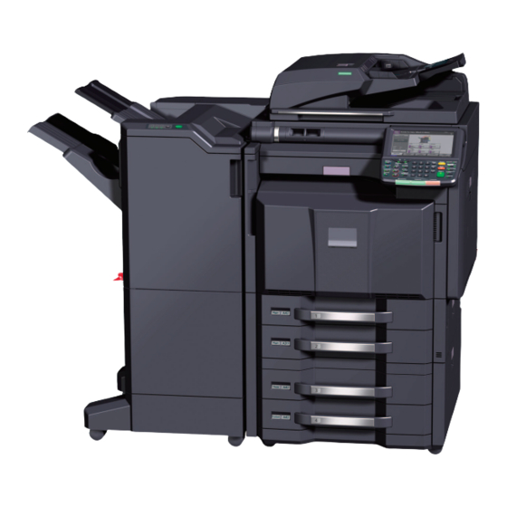
- Page 19 2LK/2LN/2LM/2LC 1-1-2 Parts names (1) Machine Figure 1-1-1 1. Original size indicator plate 11. Handles 2. Slit glass 12. Release button 3. Toner container K 13. Waste toner box 4. Toner container M 14. Waste toner tray 5. Toner container C 15.
- Page 20 2LK/2LN/2LM/2LC Figure 1-1-2 21. Inner tray 31. Paper conveying unit lever 22. Document processor (option) 32. Duplex cover lever 23. Original cover 33. Duplex cover 24. USB port 34. MP paper width guide 25. Cassettes 35. MP support Tray 26. Paper length guide 36.
- Page 21 2LK/2LN/2LM/2LC-2 (2) Option 5, 9 Figure 1-1-3 1. Machine 8. Side paper feeder 2. Document processor (dual scan DP) 9. Side large capacity feeder 3. Document processor (reversed DP) 10. 1000-sheet finisher 4. Paper feeder 11. 4000-sheet finisher 5. Large capacity feeder 12.
- Page 22 2LK/2LN/2LM/2LC (3) Operation panel 16 17 18 19 22 23 24 25 26 27 28 Figure 1-1-4 1. Program key 11. Power key 21. Memory indicator 2. Status/Job cancel key 12. Counter key 22. Numeric keys 3. Copy key 13. Main power indicator 23.
- Page 23 2LK/2LN/2LM/2LC 1-1-3 Machine cross section Paper Path Figure 1-1-5 1. Cassette paper feed section 8. Drum unit C 15. Primary transfer section 2. MP tray paper feed section 9. Drum unit Y 16. Secondary transfer/Separa- 3. Paper conveying section 10. Developer unit K tion sections 4.
- Page 24 2LK/2LN/2LM/2LC This page is intentionally left blank. 1-1-10...
- Page 25 2LK/2LN/2LM/2LC 1-2 Installation 1-2-1 Installation environment 1. Temperature: 10 to 32.5°C/50 to 90.5°F 2. Humidity: 15 to 80% RH 3. Power supply: 120 V AC, 12.0 A 220 - 240 V AC, 7.2 A 4. Power source frequency: 50 Hz ± 2%/60 Hz ± 2% 5.
- Page 26 2LK/2LN/2LM/2LC-2 1-2-2 Unpacking and installation (1) Installation procedure Start Unpacking Installing the waste toner box Replacing operation panel sheet Removing the eject spacer Installing the original platen or DP (option) Removing the tapes Installing other optional devices Installing the paper feeder (option) Installing the cassette heater (option) Release the lock of the scanner mirror frame Connect the power cord...
- Page 27 2LK/2LN/2LM/2LC Moving the machine When moving the machine, pull out three carrying handles, and move with carrying handles and the hand- hold. Carrying Handhold handle Carrying handle Carrying handle Figure 1-2-2 1-2-3...
- Page 28 2LK/2LN/2LM/2LC-2 Unpacking 16,17, 18,19,20 Figure 1-2-3 1. Machine 13. Machine cover 2. Outer case 14. Document tray 3. Inner case 15. Power cord 4. Top pad 16. Plastic bag 5. Skid 17. Paper size plates 6. Bottom sheet 18. Paper media plates 7.
- Page 29 2LK/2LN/2LM/2LC-2 Removing the eject spacer 1. Remove the eject spacer and silica gel from the eject section. Waste toner box Eject spacer Silica gel Figure 1-2-4 Removing the tapes 1. Remove three tapes and then remove Tape A3 papers two A3 papers. 2.
- Page 30 2LK/2LN/2LM/2LC-2 3. Remove eight tapes. Tape Tape Tape Tape Tapes Tapes Figure 1-2-6 Installing the paper feeder (option) 1. Install the optional paper feeder or large capacity feeder as necessary. 2. Verify levelness at the four corners of the contact glass using a level gauge, and adjust the level bolts at the bottom of the machine to optimize levelness.
- Page 31 2LK/2LN/2LM/2LC Release the lock of the scanner mirror frame 1. Remove the scanner lock cover. 2. Mount the scanner lock cover in the reverse manner to restore in the original location. Scanner lock cover [Released] [Locked] Figure 1-2-7 1-2-7...
- Page 32 2LK/2LN/2LM/2LC Release of lift plate stopper 1. Pull cassette 1 and 2 out. 2. Remove the lift plate stopper from each cassette and attach it to the storage location. When moving the machine, attach the lift plate in original position. Lift plate stopper Cassette...
- Page 33 2LK/2LN/2LM/2LC 2. Press the guide lock lever to release the lock. 3. Grasp the paper width adjusting tab and move the paper width guides to fit the paper. Guide lock lever Paper width paper width guides adjusting tab Figure 1-2-10 4.
- Page 34 2LK/2LN/2LM/2LC 5. Press the guide lock lever to lock. Guide lock lever Figure 1-2-12 6. Fold the paper size plate and the paper Paper media plate media plate in two and insert. 7. Gently push the cassette back in. Paper size plate Figure 1-2-13 1-2-10...
- Page 35 2LK/2LN/2LM/2LC Installing the toner containers 1. Open the front cover. 2. Hold the toner container vertically and hit the upper part about 3 times. Invert the toner container so that the other end is up, and hit in the same way. 3.
- Page 36 2LK/2LN/2LM/2LC-2 Unlocking the developer waste exit Caution To ease setup, the device was shipped with the developer unit already replenished with developer. Therefore, to prevent developer from spilling during shipping, a developer shutter is equipped with the developer unit. To disengage the shutter, use the following procedure: Note that if the shutter is not completely disengaged and retained in place, the developer in the developer unit...
- Page 37 2LK/2LN/2LM/2LC-2 Installing the waste toner box Caution Before installing the waste toner box, Waste toner tray unlock the developer waste exit (see page 1-2-12). 1. Push the release button and pull out the waste toner tray. 2. Open the lid and install the waste toner box.
- Page 38 2LK/2LN/2LM/2LC-2 Replacing operation panel sheet 1. Insert a flat-head screwdriver and slide the operation panel covers A and B to remove them. Operation panel cover B Operation panel cover A Figure 1-2-19 2. Remove the clear panel. Clear panel Figure 1-2-20 1-2-14...
- Page 39 2LK/2LN/2LM/2LC-2 3. Remove the operation panel sheet. Operation 4. Replace the operation panel sheet of panel sheet the corresponding language. 5. Refit the clear panel. 6. Refit the operation panel covers A and Figure 1-2-21 Installing the original platen or DP (option) 1.
- Page 40 2LK/2LN/2LM/2LC Adjusting the image 1. Turn the main power switch on. 2. Check the messages on the operation panel After completion of warming up, in case to display "Warning for high temperature. Adjust the room tem- perature." on the operation panel, follow the step 3. (Performing Drum Refresh) In case to display “Warning for low temperature.
- Page 41 2LK/2LN/2LM/2LC-2 7. Make test copies. If image quality is unsatisfactory after test copying, execute Color Calibration, then retry U410-Adjusting the halftone automatically. 8. Setting the delivery date (see page 1-3-141) Enter 278 using the numeric keys and press the start key. Select [Today].
- Page 42 2LK/2LN/2LM/2LC-2 (2) Setting initial copy modes Factory settings are as follows: Maintenance Contents Factory setting item No. U253 Switching between double and single counts DBL(A3/Ledger) U260 Selecting the timing for copy counting Eject U276 Setting the copy count mode Mode0 U284 Setting 2 color copy mode U285...
- Page 43 2LK/2LN/2LM/2LC-2 1-2-3 Installing the key counter (option) (1) Installing directly on the device Key counter installation requires the following parts: Parts Quantity Part.No. Key counter 3025418011 Key counter set 302A369708 Key counter wire 302K946AJ0 M4 nut 3CY06030 Supplied parts of key counter set (302A369708): Parts Quantity Part.No.
- Page 44 2LK/2LN/2LM/2LC-2 Procedure 1. Press the power key on the operation Key counter M4 x 6 screw panel to off. Make sure that the power retainer indicator and the memory indicator are M4 x 6 screw off before turning off the main power M3 nut switch.
- Page 45 2LK/2LN/2LM/2LC-2 8. Cut out the aperture plate on the right upper cover using nippers. Aperture Right upper cover Figure 1-2-24 9. Remove seven screws and then remove the rear upper cover. Rear upper cover Screws Screws Screws Screw Figure 1-2-25 1-2-21...
- Page 46 2LK/2LN/2LM/2LC-2 10. Open the controller lid. 11. Remove two screws. 12. Unhook six hooks and then remove the left upper cover. Left upper cover Controller lid Screws Hooks Hook Left upper cover Hooks Figure 1-2-26 13. Release six wire saddles on the control- Wire holder ler box.
- Page 47 2LK/2LN/2LM/2LC-2 15. Remove the following connectors that connected to the main PWB from the outside of the control box. YC25 YC11 YC30 YC24 YC3 (FFC connector with a lock) YC17 (BK) Controller box YC21 (WH) Main PWB YC12 YC12 YC17 YC25 *: When removing the FFC from the FFC YC21...
- Page 48 2LK/2LN/2LM/2LC-2 16. Remove five screws. 17. Unhook two hooks and then remove the controller box. Controller box Hook Hook Screws Screws Screw Figure 1-2-29 18. Connect the connector of the key coun- ter wire to the connector YC24 on the engine PWB.
- Page 49 2LK/2LN/2LM/2LC-2 19. Remove two wire holders. 20. Route the key counter wire through the wire guide and fix it at the wire holders. key counter wire Wire guide Wire holders Figure 1-2-31 21. Release three wire saddles. Wire guide 22. Remove the wire holder. 23.
- Page 50 2LK/2LN/2LM/2LC-2 26. Mount two M4 nuts at the back of the M4 nuts right upper cover. Right upper cover Figure 1-2-33 27. Insert the projection of the key counter Right upper cover cover retainer in the aperture of the right upper cover. 28.
- Page 51 2LK/2LN/2LM/2LC-2 29. Pass the connector of the key counter wire through the aperture in the right upper cover. Right upper cover 30. Refit the right upper cover. Aperture 31. Refit the ISU right cover. 32. Close the paper conveying unit. Key counter wire Figure 1-2-35 33.
- Page 52 2LK/2LN/2LM/2LC-2 (2) Mounting on the document table Key counter installation requires the following parts: Parts Quantity Part.No. Key counter 3025418011 Key counter set 302A369708 Key counter wire 302K946AJ0 Document table 1902H70UN1 (option) Supplied parts of key counter set (302A369708): Parts Quantity Part.No.
- Page 53 2LK/2LN/2LM/2LC-2 Procedure 1. Perform steps 1 through 25 as M4 nut M4 nut explained in (1) Installing directly on the device. 2. Mount two M4 nuts at the back of the right upper cover. 3. Fit the tray stay to the right upper cover using two M4 x 14 screws.
- Page 54 2LK/2LN/2LM/2LC-2 4. Fit the tray retainer to the machine Tray retainer using the M4 x 8 screw. *: The procedure described above is not required if an optional right job separator has been installed. M4 x 8 screw M4 x 8 screw Tray retainer Figure 1-2-38 5.
- Page 55 2LK/2LN/2LM/2LC-2 9. Snap in the tray mount to the tray stay M4 x 8 screw and fix using two M4 x 8 screws. Tray mount Figure 1-2-40 1-2-31...
- Page 56 2LK/2LN/2LM/2LC-2 10. Cut out the aperture plate on the tray cover using nippers. Tray cover 11. Fit the tray cover to the tray stay using four M4 x 8 screws. Aperture M4 x 8 screws M4 x 8 screws Tray cover Figure 1-2-41 12.
- Page 57 2LK/2LN/2LM/2LC-2 13. Pass the key counter signal cable through the aperture in the document table. M4 x 6 screw Key counter 14. Fit the key counter cover to the docu- cover ment table using the M4 x 6 screw. 15. Connect the key counter signal cable to the key counter wire.
- Page 58 2LK/2LN/2LM/2LC-2 16. Fit the tray lower cover. Install the key counter signal cable and key counter wire so that they are held behind the tray lower cover. Tray lower cover Connector Figure 1-2-44 1-2-34...
- Page 59 2LK/2LN/2LM/2LC-2 17. Secure the tray lower cover with two pins. Tray lower cover Figure 1-2-45 18. Adhere the sheet onto right side of the Sheet document table. 19. Insert the key counter into the key counter socket assembly. 20. Turn the main power switch on and enter the maintenance mode.
- Page 60 2LK/2LN/2LM/2LC-2 1-2-4 Installing the key card MK-2 (option for japan only) Key card installation requires the following parts: Parts Quantity Part.No. Key card MK-2 8J272002 (option) MK-2 mount Supplied with MK-2 M4 x 16 screw Document table 1902H70UN1 (option) M4 x 20 tap-tight S screw 7BB100420H 1-2-36...
- Page 61 2LK/2LN/2LM/2LC-2 Procedure 1. Press the power key on the operation Screws panel to off. Make sure that the power ISU right indicator and the memory indicator are cover off before turning off the main power Right upper cover switch. And then unplug the power cable from the wall outlet.
- Page 62 2LK/2LN/2LM/2LC-2 6. Open the controller lid. 7. Remove two screws. 8. Unhook six hooks and then remove the left upper cover. Left upper cover Controller lid Screws Hooks Hook Left upper cover Hooks Figure 1-2-49 9. Release six wire saddles on the control- Wire holder ler box.
- Page 63 2LK/2LN/2LM/2LC-2 11. Remove the following connectors that connected to the main PWB from the outside of the control box. YC25 YC11 YC30 YC24 YC3 (FFC connector with a lock) YC17 (BK) Controller box YC21 (WH) Main PWB YC12 YC12 YC17 YC25 *: When removing the FFC from the FFC YC21...
- Page 64 2LK/2LN/2LM/2LC-2 12. Remove five screws. 13. Unhook two hooks and then remove the controller box. Controller box Hook Hook Screws Screws Screw Figure 1-2-52 14. Cut out the aperture plate on the right upper cover using nippers. Aperture Right upper cover Figure 1-2-53 1-2-40...
- Page 65 2LK/2LN/2LM/2LC-2 15. Mount two M4 nuts at the back of the M4 nut M4 nut right upper cover. 16. Fit the tray stay to the right upper cover using two M4 x 14 screws. Right upper cover M4 nut M4 nut Tray stay M4 x 14 screw Right upper cover...
- Page 66 2LK/2LN/2LM/2LC-2 17. Snap in the tray mount to the tray stay M4 x 8 screw and fix using two M4 x 8 screws. Tray mount Figure 1-2-55 18. Cut out the aperture plate on the tray cover using nippers. Figure 1-2-56 1-2-42...
- Page 67 2LK/2LN/2LM/2LC-2 19. Pass the MK-2 signal cable through the MK-2 aperture in the tray cover, tray stay and right upper cover. MK-2 signal cable Aperture Tray corer Aperture MK-2 signal cable Figure 1-2-57 1-2-43...
- Page 68 2LK/2LN/2LM/2LC-2 20. Connect the connector of the MK-2 sig- nal cable to the connector YC25 on the engine PWB. Ground terminal 21. Remove the screw from the machine. 22. Fix the MK-2 signal cable to the ground terminal with the screw that was Screw removed.
- Page 69 2LK/2LN/2LM/2LC-2 23. Remove three wire holders. Scanner 24. Route the MK-2 signal cable through Wire guide motor the wire guide and fix it at three wire holders. *: Dress the MK-2 signal wire away from the scanner motor and fix. 25.
- Page 70 2LK/2LN/2LM/2LC-2 27. Fit the tray retainer to the machine Tray retainer using the M4 x 8 screw. *: The procedure described above is not required if an optional right job separator has been installed. M4 x 8 screw M4 x 8 screw Tray retainer Figure 1-2-60 28.
- Page 71 2LK/2LN/2LM/2LC-2 32. Remove the four screws securing the MK-2 cover; attach the MK-2 mount to the MK-2, and secure using the four screws. MK-2 Screws Screws MK-2 Screws MK-2 mount Screws Figure 1-2-62 33. Fit the MK-2 to the document table M4 x 20 using two M4 x 20 tap-tight S screws.
- Page 72 2LK/2LN/2LM/2LC-2 34. Fit the tray lower cover. 35. Secure the tray lower cover with two pins. Tray lower cover Figure 1-2-64 1-2-48...
- Page 73 2LK/2LN/2LM/2LC-2 36. Adhere the sheet onto right side of the Sheet document table. 37. Turn the main power switch on and enter the maintenance mode. 38. Run maintenance item U204 and select [Key-Card] (see page 1-3-110). Document table 39. Exit the maintenance mode. Figure 1-2-65 1-2-49...
- Page 74 2LK/2LN/2LM/2LC-2 1-2-5 Installing the KMAS (option for japan only) KMAS installation requires the following parts: Using the PHS module Parts Quantity Part.No. PHS module HM000080 (option) PHS signal cable 023CK200 (option) KMAS interface PWB 023CK000 (option) M3 x 16 bronze binding screw B3323160 Ferrite core 2A027770...
- Page 75 2LK/2LN/2LM/2LC-2 Procedure To fix KMAS, perform the following procedure: Start Setting the DIP switch Fitting the KMAS interface PWB Using the PHS module Using a modem Fitting the PHS signal cable Fitting the RS-232C signal cable and PHS module Initializing the KMAS 1-2-51...
- Page 76 2LK/2LN/2LM/2LC-2 Setting the DIP switch 1. Configure DIP switches 1 to 4 on the KMAS interface board as follows: DIP switch Figure 1-2-66 DIP SW No. Description Remarks PHS module/modem switching ON: Use modem OFF: Use PHS module Modem outgoing switching This is required when modem is used.
- Page 77 2LK/2LN/2LM/2LC-2 Fitting the KMAS interface PWB 2. Remove seven screws and then remove the rear upper cover. Rear upper cover Screws Screws Screws Screw Figure 1-2-67 3. Attach one spacer A and three spacers Controller box B to the side of the controller box. Spacer B Spacer A Spacer B...
- Page 78 2LK/2LN/2LM/2LC-2 4. Insert the KMAS interface PWB to three Spacer B spacers B. Spacer B Spacer B KMAS interface PWB Figure 1-2-69 5. Remove YC7 and YC23 on the main PWB and connector of the controller fan Main PWB mor. Remove the relay wire. Relay wire YC23 Controller...
- Page 79 2LK/2LN/2LM/2LC-2 6. Connect the connector of the KMAS wire to the connector YC1 on the KMAS PWB. 7. Connect the connector of the KMAS wire to controller fan motor, YC7 and YC23 on the main PWB. KMAS wire KMAS interface PWB Main PWB KMAS wire YC23...
- Page 80 2LK/2LN/2LM/2LC-2 8. Pass the KMAS wire through the edging of the controller box and wire saddle and then fasten the KMAS wire. Edging KMAS wire Wire saddle Figure 1-2-72 Fitting the PHS signal cable and PHS mod- Rear upper cover 9.
- Page 81 2LK/2LN/2LM/2LC-2 12. Connect the connector of the PHS sig- nal cable to the connector YC2 on the KMAS KMAS interface PWB. interface PWB 13. Refit the rear upper cover. PHS signal cable Figure 1-2-74 14. Fit the PHS module to rear upper cover using two M3 x 16 screws.
- Page 82 2LK/2LN/2LM/2LC-2 15. Wrap the PHS signal cable around the ferrite core a turn. 16. Connect the connector of the PHS sig- nal cable to PHS module. 17. Fit the clamp to PHS signal cable. PHS module 18. After using alcohol to clean the rear upper cover, adhere the clamp to rear upper cover.
- Page 83 2LK/2LN/2LM/2LC-2 1-2-6 Installing the coin vender (option for japan only) Coin vender installation requires the following parts: Parts Quantity Part.No. 1905H99JP0 (option) Coin vender Vender wire Supplied with Ferrite core coin vender Clamp Vender signal cable 302K946AE0 Procedure 1. Press the power key on the operation panel to off.
- Page 84 2LK/2LN/2LM/2LC-2 3. Remove seven screws and then remove the rear upper cover. Rear upper cover Screws Screws Screws Screw Figure 1-2-78 4. Remove eight screws. 5. Release two hanging parts and then remove the rear lower cover. Screw Screw Screws Rear lower cover Screws Figure 1-2-79...
- Page 85 2LK/2LN/2LM/2LC-2 6. Remove two screws and then remove the lid. Screws Figure 1-2-80 7. Connect the connector of the vender YC23 Engine PWB Wire guide signal cable to the connector YC23 on the engine PWB. 8. Pass the vender signal cable through the wire guide and ten wire saddles and then fasten the cable.
- Page 86 2LK/2LN/2LM/2LC-2 9. Pass the vender wire through the aper- ture in the IF mount. 10. Secure the vender wire with two screws Ground removed in step 6. terminal 11. Secure the ground terminal of the vender wire to rear frame with the screw.
- Page 87 2LK/2LN/2LM/2LC-2 15. Fit the ferrite core to signal cable of coin vender. Coin vender 16. Fit the clamp to signal cable of coin vender. 17. Remove a screw from the coin vender Clamp and fix the coin vender with a clamp. Screw Ferrite core Signal cable...
- Page 88 2LK/2LN/2LM/2LC-2 1-2-7 Installing the cassette heater (option) Cassette heater installation requires the following parts: Parts Quantity Part.No. Cassette heater set (120V) 302K994930 Cassette heater set (240V) 302K994940 Supplied parts of cassette heater set (302K994930): Parts Quantity Part.No. Cassette heater (120V) 302H794620 Wire saddle 7YZM610001++H0...
- Page 89 2LK/2LN/2LM/2LC-2 Procedure 1. Press the power key on the operation panel to off. Make sure that the power indicator and the memory indicator are off before turning off the main power switch. And then unplug the power cable from the wall outlet. 2.
- Page 90 2LK/2LN/2LM/2LC-2 6. Fit three wire saddles on the bottom frame of the machine. 7. Fit the cassette heater using two M3 x 8 screws. Wire saddle Wire saddle Screw Wire saddle Screw Cassette heater Figure 1-2-88 1-2-66...
- Page 91 2LK/2LN/2LM/2LC-2 8. Connect the connector of the cassette heater to the connector in the rear frame of the machine. 9. Pass the wire of the cassette heater through three wire saddles and then fasten the wire. Wire saddle Wire saddles Cassette heater Connector Figure 1-2-89...
- Page 92 2LK/2LN/2LM/2LC-2 1-2-8 Installing the gigabit ethernet board (option) Procedure 1. Press the power key on the operation panel to off. Make sure that the power indicator and the memory indicator are Slot cover off before turning off the main power switch.
- Page 93 2LK/2LN/2LM/2LC-2 5. Plug the modular connector cable into the line terminal, Controller lid 6. Close the controller lid. Modular connector cable Figure 1-2-92 1-2-69...
- Page 94 2LK/2LN/2LM/2LC-2 This page is intentionally left blank. 1-2-70...
- Page 95 2LK/2LN/2LM/2LC 1-3 Maintenance Mode 1-3-1 Maintenance mode The machine is equipped with a maintenance function which can be used to maintain and service the machine. (1) Executing a maintenance item Start Enter “10871087” using Maintenance mode is entered. the numeric keys. Enter the maintenance item The maintenance item is selected.
- Page 96 2LK/2LN/2LM/2LC-2 (2) Maintenance modes item list Initial setting Item Section Content of maintenance item 30ppm 35ppm 45ppm 55ppm General U000 Outputting an own-status report U001 Exiting the maintenance mode U002 Setting the factory default data U003 Setting the service telephone number U004 Setting the machine number U010 Setting the maintenance mode ID U019 Displaying the ROM version...
- Page 97 2LK/2LN/2LM/2LC-2 Initial setting Item Section Content of maintenance item 30ppm 35ppm 45ppm 55ppm Drive, U053 Moter3 -51/0/ -44/0/ -34/0/ -30/0/ paper feed -77/-77/ -66/-66/ -51/-51/ -46/-41/ and paper 0/0/-/-/-/ 0/0/-/-/-/ 0/0/0/ 0/0/0/ conveying 0/0/0/0 0/0/0/0 -50/-50/ -45/-45/ system 0/0/0/0 0/0/0/0 Moter4 -/42 -/36...
- Page 98 2LK/2LN/2LM/2LC-2 Initial setting Item Section Content of maintenance item 30ppm 35ppm 45ppm 55ppm Optical U089 Outputting a MIP-PG pattern U091 Setting the white line correction 112/112/112/75/0 U099 Adjusting original size detection DP is not installed 20/30/40/20/30/40/20/30/40 DP is installed 50/50/50/50/50/50/50/50/50 High U100 Adjusting main high voltage voltage...
- Page 99 2LK/2LN/2LM/2LC-2 Initial setting Item Section Content of maintenance item 30ppm 35ppm 45ppm 55ppm High U106 Heavy2-5 1st Half 114/111/ 118/115/ 126/123/ 130/127/ voltage Heavy2-5 2nd Half 126/123/ 132/128/ 144/140/ 151/146/ 118/115/ 123/120/ 134/129/ 139/133/ Bias 163/163/ 1/1/1/-/ 1/1/1/-/ 1/1/1/1/ 1/-/122/ 127/118/ 138/126/ 143/130/...
- Page 100 2LK/2LN/2LM/2LC-2 Initial setting Item Section Content of maintenance item 30ppm 35ppm 45ppm 55ppm Developer U140 Displaying developer bias 70/70/ Sleeve DC 62/62/62/62/- 70/70/ 70/70/- 70/70/70 155/155/ Sleeve AC 175/175/175/175/- 155/155/ 155/155/ 155/155/ 155/155/ Mag DC 130/130/130/130/- 155/155/ 155/155/ 155/155/ Mag AC 101/101/101/101/- 160/200/ 160/200/...
- Page 101 2LK/2LN/2LM/2LC-2 Initial setting Item Content of maintenance item Section 30ppm 35ppm 45ppm 55ppm Fuser U169 Checking/setting the fuser power source U199 Displaying fuser heater temperature Operation U200 Turning all LEDs on panel and U201 Initializing the touch panel support U202 Setting the KMAS host monitoring system equipment U203 Checking DP operation U204 Setting the presence or absence of a key...
- Page 102 2LK/2LN/2LM/2LC-2 Initial setting Item Section Content of maintenance item 30ppm 35ppm 45ppm 55ppm Mode U250 Checking/clearing the maintenance cycle setting U251 Checking/clearing the maintenance coun- U252 Setting the destination U253 Switching between double and single DBL(A3/Ledger) counts U260 Selecting the timing for copy counting Eject U265 Setting OEM purchaser code U271 Setting the page count...
- Page 103 2LK/2LN/2LM/2LC-2 Initial setting Item Section Content of maintenance item 30ppm 35ppm 45ppm 55ppm Image U411 Adjusting the scanner automatically processing U412 Adjusting the uneven density U415 Adjusting the print position automatically U425 Setting the target U429 Setting the offset for the color balance 0/0/0/0 U460 Adjusting the conveying sensor U464 Setting the ID correction operation...
- Page 104 2LK/2LN/2LM/2LC-2 Initial setting Item Section Content of maintenance item 30ppm 35ppm 45ppm 55ppm Others U906 Resetting partial operation control U908 Checking the total counter value U910 Clearing the print coverage data U911 Checking copy counts by paper sizes U917 Setting backup data reading/writing U920 Checking the copy counts U927 Clearing the all copy counts and machine life counts (one time only)
- Page 105 2LK/2LN/2LM/2LC (3) Contents of the maintenance mode items Item No. Description U000 Outputting an own-status report Description Outputs lists of the current settings of the maintenance items, and paper jam and service call occurrences. Outputs the event log or service status page. Also sends output data to the USB memory.
- Page 106 2LK/2LN/2LM/2LC Item No. Description U000 Method: Send to the USB memory 1. Press the power key on the operation panel, and after verifying the main power indicator has gone off, switch off the main power switch. 2. Insert USB memory in USB memory slot. 3.
- Page 107 2LK/2LN/2LM/2LC Item No. Description U000 Event log Event Log 27/Oct/2010 08:40 Firmware version 2LC_2000.000.000 2010.10.27 [XXXXXXXX] [XXXXXXXX] [XXXXXXXX] [XXXXXXXX] (12) Paper Jam Log Counter Log Count. Event Descriprions J0000: J0041: C0000: T00: 9999999 0501.01.08.01.01 J0001: J0042: C0001: T01: 8888888 4002.01.08.01.01 J0002: J0043: C0002:...
- Page 108 2LK/2LN/2LM/2LC-2 Item No. Description U000 Detail of event log Items Description Controller BROM version Operation panel mask version Machine serial number Paper Jam Count. Event Remembers 1 to 16 of The total page count Log code (hexadeci- occurrence. If the occur- at the time of the mal, 5 categories) rence of the previous...
- Page 109 2LK/2LN/2LM/2LC Item No. Description U000 Items Description Paper Jam (d) Detail of paper type (Hexadecimal) cont. 01: Plain 0A: Color 15: Custom 1 02: Transparency 0B: Prepunched 16: Custom 2 03: Preprinted 0C: Envelope 17: Custom 3 04: Labels 0D: Cardstock 18: Custom 4 05: Bond 0E: Coated...
- Page 110 2LK/2LN/2LM/2LC Item No. Description U000 Items Description Service Call Count. Service Code Remembers 1 to 8 The total page Self diagnostic error code of occurrence of self count at the time of (See page 1-4-28) diagnostics error. If the self diagnostics the occurrence of error.
- Page 111 2LK/2LN/2LM/2LC Item No. Description U000 Items Description (12) Counter Log (f) Paper jam (g) Self diagnostic (h) Maintenance item error replacing Comprised of Indicates the log Indicates the log Indicates the log coun- three log coun- counter of paper counter of self diag- ter depending on the ters including jams depending on...
- Page 112 2LK/2LN/2LM/2LC-2 Item No. Description U000 Service status page (1) Service Status Page 27/10/2010 12:00 Firmware version 2LC_2000.000.000 2010.10.27 [XXXXXXXX] [XXXXXXXX] [XXXXXXXX] Controller Information (29) FAX Information Slot1/Slot2 (30) Rings (Normal) Memory status (31) Rings (FAX/TEL) Total Size 2.0 GB (32) Rings (TAD) (33) Option DIMM Size...
- Page 113 2LK/2LN/2LM/2LC-2 Item No. Description U000 Service status page (2) Service Status Page 27/10/2010 12:00 Firmware version 2LC_2000.000.000 2010.10.27 [XXXXXXXX] [XXXXXXXX] [XXXXXXXX] Engine Information Send Information (39) NVRAM Version _1F31225_1F31225 (43) Date and Time 10/10/27 (49) Scanner Version 2LC_1200.001.089 (44) Address (41) FAX Slot1 FAX BOOT Version...
- Page 114 2LK/2LN/2LM/2LC-2 Item No. Description U000 Detail of service status page Description Supplement Firmware version System date Engine soft version Engine boot version Operation panel mask version Machine serial number Total memory size Local time zone Report output date Day/Month/Year hour:minute (10) NTP server name (11)
- Page 115 2LK/2LN/2LM/2LC-2 Item No. Description U000 Description Supplement (28) Coverage on the final output page (29) Fax kit information This item is printed only when the fax kit is installed. (30) Number of rings 0 to 15 (31) Number of rings before auto- 0 to 15 matic switching (32)
- Page 116 2LK/2LN/2LM/2LC-2 Item No. Description U000 Description Supplement (44) Transmission address (45) Destination information (46) Area information (47) Margin settings Top margin/Left margin (48) Margin/Page length/Page width Top margin integer part/Top margin decimal part/ settings Left margin integer part/Left margin decimal part/ Page length integer part/Page length decimal part/ Page width integer part/Page width decimal part (49)
- Page 117 2LK/2LN/2LM/2LC-2 Item No. Description U000 Description Supplement (64) Media type attributes Weight settings Fuser settings 1 to 28 (Not used: 18, 19, 20) 0: Light 0: High 1: Normal 1 1: Middle 2: Normal 2 2: Low 3: Normal 3 3: Vellum 4: Heavy 1 Duplex settings...
- Page 118 2LK/2LN/2LM/2LC-2 Item No. Description U000 Description Supplement (89) Drum serial number Black/Cyan/Magenta/Yellow Code conversion U001 Exiting the maintenance mode Description Exits the maintenance mode and returns to the normal copy mode. Purpose To exit the maintenance mode. Method 1. Press the start key. The normal copy mode is entered. U002 Setting the factory default data Description...
- Page 119 2LK/2LN/2LM/2LC-2 Item No. Description U003 Setting the service telephone number Description Sets the telephone number to be displayed when a service call code is detected. Purpose To set the telephone number to call service when installing the machine. Setting 1. Press the start key. The keys to enter the number are displayed on the touch panel.
- Page 120 2LK/2LN/2LM/2LC Item No. Description U010 Setting the maintenance mode ID Description Sets the maintenance mode ID. Purpose Modify maintenance mode ID for more security. Method 1. Press the start key. Display Description New ID Enter a new 8-digit ID New ID(Reconfirm) Enter a new 8-digit ID (to confirm) Initialize Initialize the ID...
- Page 121 2LK/2LN/2LM/2LC-2 Item No. Description U019 Displaying the ROM version Description Displays the part number of the ROM fitted to each PWB. Purpose To check the part number or to decide, if the newest version of ROM is installed. Method 1. Press the start key. The ROM version are displayed. 2.
- Page 122 2LK/2LN/2LM/2LC-2 Item No. Description U019 Display Description Side PF Boot Side multi tray /Side deck booting SMT SSW Side multi tray multi feed sensor Side paper feeder / Side large capacity feeder ROM PF2 Boot Side paper feeder / Side large capacity feeder booting 1000-sheet finisher / 4000-sheet finisher ROM DF Boot 1000-sheet finisher / 4000-sheet finisher booting...
- Page 123 2LK/2LN/2LM/2LC Item No. Description U021 Memory initializing Description Initializes all settings, except those pertinent to the type of machine, namely each counter, ser- vice call history and mode setting. Also initializes backup RAM according to region specification selected in maintenance item U252 Setting the destination. Purpose To return the machine settings to their factory default.
- Page 124 2LK/2LN/2LM/2LC Item No. Description U024 HDD formatting Description Initializes the hard disk. Purpose To initialize the hard disk when replacing the hard disk after shipping. Caution In addition, the following settings are also initialized by initializing the hard disk. System menu (user login administration, job accounting, address book, one-touch keys and doc- ument box etc.), shortcuts and panel programs When fully formatted, the following pre-installed software are removed.
- Page 125 2LK/2LN/2LM/2LC-2 Item No. Description U030 Checking the operation of the motors Description Drives each motor. Purpose To check the operation of each motor. Method 1. Press the start key. 2. Select the motor to be operated. 3. Press the start key. The operation starts. Display Description Feed...
- Page 126 2LK/2LN/2LM/2LC-2 Item No. Description U031 Checking switches and sensors for paper conveying Description Displays the on-off status of each paper detection switch or sensor on the paper path. Purpose To check if the switches and sensors for paper conveying operate correctly. Method 1.
- Page 127 2LK/2LN/2LM/2LC Item No. Description U032 Checking the operation of the clutches Description Turns each clutch on. Purpose To check the operation of each clutch. Method 1. Press the start key. 2. Select the clutch to be operated. 3. Press the start key. The operation starts. Display Description Feed1...
- Page 128 2LK/2LN/2LM/2LC-2 Item No. Description U033 Checking the operation of the solenoids Description Turns each solenoid on. Purpose To check the operation of each solenoid. Method 1. Press the start key. 2. Select the solenoid to be operated.z 3. Press the start key. The operation starts. Display Description Branch Exit...
- Page 129 2LK/2LN/2LM/2LC-2 Item No. Description U034 Adjustment: Leading edge registration adjustment 1. Press the system menu key. 2. Press the start key to output a test pattern. 3. Press the system menu key. 4. Select the item to be adjusted. [LSU Out Top] Setting Initial Change in...
- Page 130 2LK/2LN/2LM/2LC-2 Item No. Description U034 5. Change the setting value using the cursor +/- or numeric keys. For output example 1, increase the value. For output example 2, decrease the value. Leading edge registration (20 ± 1.0 mm) Correct image Output Output example 1...
- Page 131 2LK/2LN/2LM/2LC-2 Item No. Description U034 5. Change the setting value using the +/- keys or numeric keys. For output example 1, increase the value. For output example 2, decrease the value. Center line of printing (within ± 2.0 mm) Correct image Output Output example 1...
- Page 132 2LK/2LN/2LM/2LC Item No. Description U035 Setting the printing area for folio paper Description Changes the printing area for copying on folio paper. Purpose To prevent cropped images on the trailing edge or left/right side of copy paper by setting the actual printing area for folio paper.
- Page 133 2LK/2LN/2LM/2LC-2 Item No. Description U037 Checking the operation of the fan motors Description Drives each fan motor. Purpose To check the operation of each fan motor. Method 1. Press the start key. 2. Select the fan motor to be operated. 3.
- Page 134 2LK/2LN/2LM/2LC-2 Item No. Description U039 Adjusting the magnification Description Adjusts the magnification of the printing. Purpose Make the adjustment if the magnification in the auxiliary scanning direction is incorrect. Caution Adjust the magnification in the following order. U065 U070 U039 (P.1-3-52) (P.1-3-57) Method...
- Page 135 2LK/2LN/2LM/2LC-2 Item No. Description U051 Adjusting the deflection in the paper Description Adjusts the deflection in the paper at the registration roller. Purpose Make the adjustment if the leading edge of the copy image is missing or varies randomly, or if the copy paper is Z-folded.
- Page 136 2LK/2LN/2LM/2LC-2 Item No. Description U051 [LSU Out Top B/W] Initial setting Setting Display Description range 30ppm 35ppm 45ppm 55ppm MPT(L) Paper feed from MP tray -30 to 20 Cassette(L) Paper feed from cassette -30 to 20 Duplex(L) Duplex mode (second) -30 to 20 MPT(S) Paper feed from MP tray...
- Page 137 2LK/2LN/2LM/2LC-2 Item No. Description U052 Setting the fuser motor control Description Enters the sensor data values described on the supplied sheet provided when the loop sensor is replaced and performs correction processing for the fuser motor. Purpose To perform when replacing the loop sensor or paper conveying unit. Method 1.
- Page 138 2LK/2LN/2LM/2LC-2 Item No. Description U053 Setting the adjustment of the motor speed Description Performs fine adjustment of the speeds of the motors. Purpose Basically, the setting need not be changed. Modify settings by interlock setting only if faulty images occur. Method 1.
- Page 139 2LK/2LN/2LM/2LC-2 Item No. Description U053 Setting: [Motor2] 1. Select the item to be adjusted. Setting Initial Display Description range setting Dev(K) Developer motor K (DEVM-K) -5000 to 5000 Dev(CMY) Developer motor MCY (DEVM-MCY) -5000 to 5000 Trans Belt Transfer motor (TRM) -5000 to 5000 Regist* Registration motor (RM)
- Page 140 2LK/2LN/2LM/2LC-2 Item No. Description U053 Setting: [Motor4] 1. Select the item to be adjusted. Initial setting Setting Display Description range 30ppm 35ppm 45ppm 55ppm Drum B/ Drum motor K (DRM-K) in -5000 to 5000 - W(K)* black/white mode Drum Drum motor K (DRM-K) in -5000 to 5000 42 Mono(K) monochrome mode...
- Page 141 2LK/2LN/2LM/2LC-2 Item No. Description U053 Setting: [Motor1 Half] 1. Select the item to be adjusted. Setting Initial Display Description range setting Drum(K) Drum motor K (DRM-K) in half speed -5000 to 5000 Setting: [Motor2 Half] 1. Select the item to be adjusted. Setting Initial Display...
- Page 142 2LK/2LN/2LM/2LC-2 Item No. Description U053 Setting: [Motor1 3/4] 1. Select the item to be adjusted. Setting Initial Display Description range setting Drum(K) Drum motor K (DRM-K) at 3/4 times of -5000 to 5000 line speed Setting: [Motor2 3/4] 1. Select the item to be adjusted. Setting Initial Display...
- Page 143 2LK/2LN/2LM/2LC-2 Item No. Description U053 Initial setting Setting Display Description range 30ppm 35ppm 45ppm 55ppm DU1* Duplex motor 1 (DUM1) -5000 to 5000 - at 3/4 times of line speed DU2* Duplex motor 2 (DUM2) -5000 to 5000 - at 3/4 times of line speed *: 45 ppm/55 ppm model only.
- Page 144 2LK/2LN/2LM/2LC-2 Item No. Description U059 Setting fan mode Description Specifies mode for paper conveying fan motors during conveying paper. Purpose Change mode if paper crease occurs. Method 1. Press the start key. 2. Select the mode. Display Description Fan Mode Sets temperature at which paper conveying fan motors operate.
- Page 145 2LK/2LN/2LM/2LC-2 Item No. Description U061 Checking the operation of the exposure lamp Description Lights the exposure lamp. Purpose To check whether the exposure lamp are turned on. Method 1. Press the start key. 2. Select the item. Display Description The exposure lamp lights The CIS lights (when dual scan DP is installed) 3.
- Page 146 2LK/2LN/2LM/2LC-2 Item No. Description U065 Adjusting the scanner magnification Description Adjusts the magnification of the original scanning. Purpose Make the adjustment if the magnification in the main scanning direction is incorrect. Make the adjustment if the magnification in the auxiliary scanning direction is incorrect. Caution The magnification adjustment along the main scanning direction could cause black streaks depending on the content of the original document.
- Page 147 2LK/2LN/2LM/2LC-2 Item No. Description U065 Adjustment: [Sub Scan] 1. Change the setting value using the +/- keys or numeric keys. For copy example 1, increase the value. For copy example 2, decrease the value. Copy Original Copy example 2 example 1 Figure 1-3-9 2.
- Page 148 2LK/2LN/2LM/2LC-2 Item No. Description U066 Adjusting the scanner leading edge registration Description Adjusts the scanner leading edge registration of the original scanning. Purpose Make the adjustment if there is a regular error between the leading edges of the copy image and original.
- Page 149 2LK/2LN/2LM/2LC-2 Item No. Description U067 Adjusting the scanner center line Description Adjusts the scanner center line of the original scanning. Purpose Make the adjustment if there is a regular error between the center lines of the copy image and original. Adjustment 1.
- Page 150 2LK/2LN/2LM/2LC Item No. Description U068 Adjusting the scanning position for originals from the DP Description Adjusts the position for scanning originals from the DP. Performs the test copy at the four scan- ning positions after adjusting. Purpose Used when the image fogging occurs because the scanning position is not proper when the DP is used.
- Page 151 2LK/2LN/2LM/2LC-2 Item No. Description U070 Adjusting the DP magnification Description Adjusts the DP original scanning speed. Purpose Make the adjustment if the magnification is incorrect in the auxiliary scanning direction when the DP is used. Make the adjustment if the magnification is incorrect in the main scanning direction when the CIS is used.
- Page 152 2LK/2LN/2LM/2LC-2 Item No. Description U070 Adjustment: [Main Scan] 1. Change the setting value using the +/- keys or numeric keys. For copy example 1, increase the value. For copy example 2, decrease the value. Copy Original Copy example 2 example 1 Figure 1-3-13 2.
- Page 153 2LK/2LN/2LM/2LC-2 Item No. Description U071 Adjusting the DP scanning timing Description Adjusts the DP original scanning timing. Purpose Make the adjustment if there is a regular error between the leading or trailing edges of the origi- nal and the copy image when the DP is used. Method 1.
- Page 154 2LK/2LN/2LM/2LC-2 Item No. Description U071 Adjustment: Leading edge registration 1. Change the setting value using the +/- keys or numeric keys. For copy example 1, increase the value. For copy example 2, decrease the value. Original Copy Copy example 1 example 2 Figure 1-3-14 2.
- Page 155 2LK/2LN/2LM/2LC-2 Item No. Description U072 Adjusting the DP center line Description Adjusts the scanning start position for the DP original. Purpose Make the adjustment if there is a regular error between the centers of the original and the copy image when the DP is used. Adjustment 1.
- Page 156 2LK/2LN/2LM/2LC-2 Item No. Description U073 Checking the scanner operation Description Simulates the scanner operation under the arbitrary conditions. Purpose To check the scanner operation. This is also done to check the accumulation of dust on the slit glass. Method 1. Press the start key. 2.
- Page 157 2LK/2LN/2LM/2LC-2 Item No. Description U073 Method: [Home Position] 1. Select [Home Position]. 2. Press the start key. The mirror frame of the scanner moves to the home position. Method: [Dust Check] 1. Select [Dust Check]. 2. Press the start key. The exposure lamp lights. 3.
- Page 158 2LK/2LN/2LM/2LC-2 Item No. Description U074 DP input response adjustment Description Sets the density correction for scanning originals from the DP. Purpose Modify the setting only if a spotted background appears when a bluish original or a document with a background that is slightly colored is scanned from the DP. Perform adjustment if the page scanned using the table and the page scanned using DP do not match.
- Page 159 2LK/2LN/2LM/2LC-2 Item No. Description U087 Setting DP reading position modification operation Description The presence or absence of dust is determined by comparing the scan data of the original trailing edge and that taken after the original is conveyed past the DP original scanning position. If dust is identified, the DP original scanning position is adjusted for the following originals.
- Page 160 2LK/2LN/2LM/2LC-2 Item No. Description U089 Outputting a MIP-PG pattern Description Selects and outputs the MIP-PG pattern created in the machine. Purpose To check copier status other than scanner when adjusting image printing, using MIP-PG pattern output (with-out scanning). Method 1. Press the start key. 2.
- Page 161 2LK/2LN/2LM/2LC-2 Item No. Description U091 Setting the white line correction Description Sets the error detection threshold value for white line correction and displays the count result of abnormal pixels. Purpose To perform when replacing the CIS, DP main PWB or CIS roller. Method 1.
- Page 162 2LK/2LN/2LM/2LC-2 Item No. Description U091 How to view test copies blank sheet black band Causes Corrective measures No lines No lines Complete Black lines White lines Dirty CIS roller or CIS Clean CIS roller or CIS glass glass and then perform U091 again Black lines No lines Engine side...
- Page 163 2LK/2LN/2LM/2LC-2 Item No. Description U099 Method: [Data1/Data2] 1. Place the original and close the original cover or DP 2. The light source illuminates and the CCD sensor determines the width of the document. The original size sensor determines the document is vertical or horizontal. (The document is detected two times when the DP is installed.) Display Description...
- Page 164 2LK/2LN/2LM/2LC-2 Item No. Description U099 Completion Press the stop key. The screen for maintenance item No. is displayed. U100 Adjusting main high voltage Description Controls the charger roller voltage to optimize the surface potential. Purpose To change the setting value to adjust the image if an image failure (background blur, etc.) occurs. Method 1.
- Page 165 2LK/2LN/2LM/2LC-2 Item No. Description U100 Displaying: [Set DC Bias] 1. The current setting is displayed. Display Description DC1 Bias(C) Main charger DC bias for cyan (full speed) DC1 Bias Half(C) Main charger DC bias for cyan (half speed) DC1 Bias(M) Main charger DC bias for magenta (full speed) DC1 Bias Half(M) Main charger DC bias for magenta (half speed)
- Page 166 2LK/2LN/2LM/2LC-2 Item No. Description U100 Setting: [Set Charger Freq] 1. Select the item to be set. 2. Change the value using the +/- or numeric keys.ll Initial setting Setting Display Description range 30ppm 35ppm 45ppm 55ppm Generally Main charger frequency 7500 to 10442 8857 8807...
- Page 167 2LK/2LN/2LM/2LC-2 Item No. Description U101 Setting the voltage for the primary transfer Description Sets the control voltage for the primary transfer. Purpose To change the setting when any density problems, such as too dark or light, occur. Setting 1. Press the start key. 2.
- Page 168 2LK/2LN/2LM/2LC-2 Item No. Description U101 Setting: [Add Color 2nd] 1. Select the item to be set. 2. Change the value using the +/- or numeric keys.l Setting Initial Display Description range setting Addition value for the second side (cyan) -127 to 127 Addition value for the second side (magenta) -127 to 127 Addition value for the second side (yellow)
- Page 169 2LK/2LN/2LM/2LC-2 Item No. Description U106 Setting the voltage for the secondary transfer Description Sets the control voltage for the secondary transfer depending on each paper type. Purpose To change the setting when any density problems, such as too dark or light, occur. Method 1.
- Page 170 2LK/2LN/2LM/2LC-2 Item No. Description U106 [1st] Initial setting Setting Display Description range 30ppm 35ppm 45ppm 55ppm Width=105 105 mm wide 0 to 255 Width=210 210 mm wide 0 to 255 Width=297 297 mm wide 0 to 255 [2nd] Initial setting Setting Display Description...
- Page 171 2LK/2LN/2LM/2LC-2 Item No. Description U106 Setting: [Normal2/3] 1. Select the item to be set. Display Description Control voltage for the transfer bias for the first side (full speed) Control voltage for the transfer bias for the second side (full speed) 1st 3/4(Gloss) Control voltage for the transfer bias for the first side at 3/4 times of line speed...
- Page 172 2LK/2LN/2LM/2LC-2 Item No. Description U106 [2nd 3/4(Gloss)] Initial setting Setting Display Description range 30ppm 35ppm 45ppm 55ppm Width=105 105 mm wide 0 to 255 Width=210 210 mm wide 0 to 255 Width=297 297 mm wide 0 to 255 [1st B/W] Initial setting Setting Display...
- Page 173 2LK/2LN/2LM/2LC-2 Item No. Description U106 [2nd 3/4] Initial setting Setting Display Description range 30ppm 35ppm 45ppm 55ppm Width=105 105 mm wide 0 to 255 Width=210 210 mm wide 0 to 255 Width=297 297 mm wide 0 to 255 4. Press the start key. The value is set. Setting: [Heavy2-5] 1.
- Page 174 2LK/2LN/2LM/2LC-2 Item No. Description U106 Setting: [Bias] 1. Select the item to be set. 2. Change the value using the +/- or numeric keys. Initial setting Setting Display Description range 30ppm 35ppm 45ppm 55ppm Reverse Transfer reverse bias 0 to 255 (full speed) Reverse Transfer reverse bias...
- Page 175 2LK/2LN/2LM/2LC-2 Item No. Description U107 Setting the transfer cleaning voltage Description Sets the cleaning control voltage for transfer belt unit. Purpose Change settings if an offset has occurred due to the failure of cleaning the transfer belt. Method 1. Press the start key. 2.
- Page 176 2LK/2LN/2LM/2LC-2 Item No. Description U108 Setting separation shift bias Description Adjusts output of separation shift bias and ON/OFF timing. Purpose To set when the separated malfunction of the paper occurs. Method 1. Press the start key. 2. Select the item to be set. Display Description Output...
- Page 177 2LK/2LN/2LM/2LC-2 Item No. Description U108 Setting: [Output 3/4 / Output B/W] 1. Select the item to be set. 2. Change the setting value using the +/- or numeric key. Setting Initial Display Description range setting Light 1st Separation shift bias for the first side on 0 to 255 paper with thickness 52 to 59 g/m Light 2nd...
- Page 178 2LK/2LN/2LM/2LC-2 Item No. Description U110 Checking the drum count Description Displays the drum counts for checking. Purpose To check the drum status. Method 1. Press the start key. The current drum counts is displayed. Display Description Drum count value for cyan Drum count value for magenta Drum count value for yellow Drum count value for black...
- Page 179 2LK/2LN/2LM/2LC-2 Item No. Description U117 Checking the drum number Description Displays the drum number. Purpose To check the drum number. Method 1. Press the start key. The drum number is displayed. Display Description Cyan drum number Magenta drum number Yellow drum number Black drum number Completion Press the stop key.
- Page 180 2LK/2LN/2LM/2LC-2 Item No. Description U119 Setting the drum Description Sets drum sensitivity. Purpose To set the drum after replacing the drum unit or laser scanner unit. Method 1. Press the start key. 2. Select [Execute]. 3. Press the start key. Drum setup is commenced. 4.
- Page 181 2LK/2LN/2LM/2LC-2 Item No. Description U123 Displaying the transfer belt unit history Description Displays the past record of machine number and the transfer belt unit counter. Purpose To check the count value of machine number and the transfer counter. Method 1. Press the start key. The history of a machine number and a transfer belt unit counter for each color is displayed by three cases.
- Page 182 2LK/2LN/2LM/2LC-2 Item No. Description U128 Setting transfer high-voltage timing Description Adjusts the ON/OFF timing of transfer high-voltage output. Purpose Basically, the setting need not be changed. If any problem such as faulty images or dirt on the back surface occurs, change the setting. Method 1.
- Page 183 2LK/2LN/2LM/2LC-2 Item No. Description U131 Adjusting the toner sensor control voltage Description Adjusts the toner sensor control voltage. Purpose If control values are not correctly retrievable due to the EEPROM of the developer unit failure, etc., use manual adjustment and obtain a temporary control value. Method 1.
- Page 184 2LK/2LN/2LM/2LC Item No. Description U131 Setting: [Mode] 1. Select the item to be set. Display Description Manual Toner sensor control voltage manual adjustment Auto Toner sensor control voltage auto adjustment Initial setting: Auto 2. Press the start key. The value is set. Completion Press the stop key.
- Page 185 2LK/2LN/2LM/2LC Item No. Description U135 Checking toner motor operation Description Drives toner motors. Purpose To check the operation of toner motors. Remarks When driving the toner motors long time or several times, developer section becomes the toner full and is locked. Method 1.
- Page 186 2LK/2LN/2LM/2LC Item No. Description U139 Displaying the temperature and humidity outside the machine Description Displays the detected temperature and humidity outside the machine. Purpose To check the temperature and humidity outside the machine. Method 1. Press the start key. 2. Select the item. Display Description Ext/Int...
- Page 187 2LK/2LN/2LM/2LC-2 Item No. Description U140 Displaying developer bias Description Displays and changes various developer bias value. Purpose To check or changes the developer bias value. Method 1. Press the start key. 2. Select the item to be set. Display Description Sleeve DC Developer sleeve roller DC bias Sleeve AC...
- Page 188 2LK/2LN/2LM/2LC-2 Item No. Description U140 Setting: [Sleeve AC] 1. Select the item to be set. 2. Change the setting value using the +/- keys or numeric keys. Initial setting Setting Display Description range 30ppm 35ppm 45ppm 55ppm Developer sleeve roller AC bias 0 to 255 for cyan Developer sleeve roller AC bias...
- Page 189 2LK/2LN/2LM/2LC-2 Item No. Description U140 Setting: [Mag AC] 1. Select the item to be set. 2. Change the setting value using the +/- keys or numeric keys. Initial setting Setting Display Description range 30ppm 35ppm 45ppm 55ppm Developer magnet roller AC bias 0 to 255 for cyan Developer magnet roller AC bias...
- Page 190 2LK/2LN/2LM/2LC-2 Item No. Description U140 Setting: [Mag Duty] 1. Select the item to be set. 2. Change the setting value using the +/- keys or numeric keys. Initial setting Setting Display Description range 30ppm 35ppm 45ppm 55ppm Normal Developer magnet roller duty 0 to 99 B/W* Developer magnet roller duty in...
- Page 191 2LK/2LN/2LM/2LC-2 Item No. Description U140 Method: [High Altitude] 1. Select Mode1 or Mode2. Display Description Mode1 Execute AC calibration by normal bias control Mode2 If print density is low in an installation at high altitude, execute calibration by fixing the bias potential. Initial setting: Mode1 2.
- Page 192 2LK/2LN/2LM/2LC-2 Item No. Description U147 Setting for toner applying operation Description Sets the mode for removing charged toner in the developing unit (T7 control: Toner applying operation). Purpose Changing settings are not required. However, when the documents with lower print density (e.g. less than 2%) should customarily printed in a great volume, mode must be changed.
- Page 193 2LK/2LN/2LM/2LC-2 Item No. Description U147 Setting: [Interval Number] 1. Select the item to be set. 2. Change the setting value using the +/- keys or numeric keys. Setting Initial Display Description range setting Print(Normal) During continuous printing (Normal environ- 10 to 500 ment) Print(H/H) During continuous printing (High humidity...
- Page 194 2LK/2LN/2LM/2LC-2 Item No. Description U155 Checking sensors for toner Description Displays the toner sensor output value. Purpose To check the output value for each color when any image problems occur. Method 1. Press the start key. 2. Select the item to be display. Display Description Waste Toner...
- Page 195 2LK/2LN/2LM/2LC Item No. Description U156 Setting the toner replenishment level Description Sets the toner replenishment level for each color. Purpose To change settings according to the original image. Method 1. Press the start key. 2. Select the item to be set. Display Description Supply...
- Page 196 2LK/2LN/2LM/2LC Item No. Description U157 Checking the developer drive time Description Displays the developer drive time for checking a figure, which is used as a reference when cor- recting the toner control. Purpose To check the developer drive time after replacing the developer unit. Method 1.
- Page 197 2LK/2LN/2LM/2LC-2 Item No. Description U161 Setting the fuser control temperature Description Changes the fuser control temperature. Purpose Normally no change is necessary. However, can be used to prevent curling or creasing of paper, or solve a fuser problem on thick paper. Method 1.
- Page 198 2LK/2LN/2LM/2LC-2 Item No. Description U161 Setting: [Print] 1. Select the item to be set. 2. Change the setting value using the +/- keys. Initial setting Setting Display Description range 30ppm 35ppm 45ppm 55ppm Full Speed Temperature at maximum 130 to 200 Print(Center) print speed (Center) (°C)
- Page 199 2LK/2LN/2LM/2LC-2 Item No. Description U167 Checking/clearing the fuser count Description Displays and clears the fuser count for checking. Purpose To check the fuser count or drive time after replacement of the fuser unit. Also to clear the counts after replacing unit. Method 1.
- Page 200 2LK/2LN/2LM/2LC Item No. Description U199 Displaying fuser heater temperature Description Displays the detected fuser temperature. Purpose To check the fuser temperature. Method 1. Press the start key. The fuser temperature is displayed. Display Description Heat Roller Edge1 Heat roller edge temperature (°C) Heat Roller Edge2 Heat roller edge temperature (°C) Heat Roller Center...
- Page 201 2LK/2LN/2LM/2LC Item No. Description U201 Initializing the touch panel Description Automatically correct the positions of the X- and Y-axes of the touch panel. Purpose To automatically correct the display positions on the touch panel after it is replaced. Method 1. Press the start key. 2.
- Page 202 2LK/2LN/2LM/2LC Item No. Description U202 Setting the KMAS host monitoring system Description Initializes or operates the KMAS host monitoring system. This is an optional device which is currently supported only by Japanese specification machines, so no setting is necessary. Purpose Performed at installation, periodic maintenance, and/or repair.
- Page 203 2LK/2LN/2LM/2LC Item No. Description U203 Checking DP operation Description Simulates the original conveying operation separately in the DP. Purpose To check the DP operation. Method 1. Press the start key. 2. Place an original in the DP if running this simulation with paper. 3.
- Page 204 2LK/2LN/2LM/2LC Item No. Description U204 Setting the presence or absence of a key card or key counter Description Sets the presence or absence of the optional key card or key counter. Purpose To run this maintenance item if a key card or key counter is installed. Method 1.
- Page 205 2LK/2LN/2LM/2LC Item No. Description U206 Setting the presence or absence of a coin vender Description Sets the presence or absence of the optional coin vender. This is an optional device which is currently supported only by Japanese specification machines. Purpose To run this maintenance item if a coin vender is installed.
- Page 206 2LK/2LN/2LM/2LC Item No. Description U206 Setting: [Price] 1. Select the item to be set. Display Description Black & White Single color C, M, Y Single color R, G, B Full Color Full color Initial setting: Off 2. Select the paper size to be set. 3.
- Page 207 2LK/2LN/2LM/2LC-2 Item No. Description U208 Setting the paper size for the side deck Description Sets the size of paper used in side deck. Purpose To change the setting when installing the side deck or the size of paper used in the side deck is changed.
- Page 208 2LK/2LN/2LM/2LC-2 Item No. Description U221 Setting the USB host lock function Description Specifies ON/OFF the USB host lock function. Setting this to ON causes the machine to be unable to recognize the device connected to the USB host. Purpose Set according to the preference of the user. Method 1.
- Page 209 2LK/2LN/2LM/2LC-2 Item No. Description U223 Operation panel lock Description Sets the operation panel lock function. Purpose This is performed to inhibit operating and canceling the system menu on the operation panel which may be done by others then an administrator. Setting 1.
- Page 210 2LK/2LN/2LM/2LC-2 Item No. Description U224 Panel sheet extension Description Changes the image data and the message of the opening screen at the machine startup and the image data and the message of the service call screen to user specified data. Purpose Set according to the preference of the user.
- Page 211 2LK/2LN/2LM/2LC-2 Item No. Description U234 Setting punch destination Description Sets the destination of punch unit of 1000-sheet finisher or 4000-sheet finisher. Purpose To be set when installing a different punch unit from the destination of the machine. Setting 1. Press the start key. 2.
- Page 212 2LK/2LN/2LM/2LC-2 Item No. Description U237 Setting finisher stack quantity Description Sets the number of sheets of each stack on the main tray and on the middle tray in 4000-sheet finisher. Purpose To change the setting when a stack malfunction has occurred. Method 1.
- Page 213 2LK/2LN/2LM/2LC Item No. Description U240 Checking the operation of the finisher Description Turns each motor and solenoid of 1000-sheet finisher or 4000-sheet finisher ON. Purpose To check the operation of each motor and solenoid of the 1000-sheet finisher or 4000-sheet fin- isher.
- Page 214 2LK/2LN/2LM/2LC Item No. Description U240 Display Description Eject Unlock(Full) DF eject release motor (DFERM) full-open drive position Punch Punch motor (PUM) is turned on Punch Move Punch slide motor (PUSLM) is turned on Method: [Solenoid] 1. Select the item to be operated. 2.
- Page 215 2LK/2LN/2LM/2LC-2 Item No. Description U241 Checking the operation of the switches of the finisher Description Displays the status of each switches and sensors of 1000-sheet finisher or 4000-sheet finisher. Purpose To check the operation of each switches and sensors of the 1000-sheet finisher or 4000-sheet finisher.
- Page 216 2LK/2LN/2LM/2LC Item No. Description U241 Display Description Match Paddle DF adjustment sensor (DFADS) Lead Paddle DF paddle sensor (DFPDS) Shift Front HP DF shift sensor 1 (DFSFS1) Shift Tail HP DF shift sensor 2 (DFSFS2) Shift Unlock HP DF shift release sensor (DFSFRS) Sub Tray Full DF sub tray full sensor (DFSTFS) Shift Set...
- Page 217 2LK/2LN/2LM/2LC Item No. Description U241 Method: [Booklet] 1. Turn each switch or sensor on and off manually to check the status. When the on-status of a switch or sensor is detected, that switch or sensor is displayed in reverse. Display Description CF paper entry sensor (CFPES) Eject...
- Page 218 2LK/2LN/2LM/2LC-2 Item No. Description U243 Checking the operation of the DP motors Description Turns the motors or solenoids in the DP on. Purpose To check the operation of the DP motors and solenoids. Method 1. Press the start key. 2. Select the item to be operated. 3.
- Page 219 2LK/2LN/2LM/2LC-2 Item No. Description U244 Checking the DP switches Description Displays the status of the respective switches and sensors in the DP. Purpose To check if respective switches and sensors in the DP operate correctly. Method 1. Press the start key. 2.
- Page 220 2LK/2LN/2LM/2LC Item No. Description U245 Checking messages Description Displays a list of messages on the touch panel of the operation panel. Purpose To check the messages to be displayed. Method 1. Press the start key. 2. Change the message using the cursor up/down keys. When a message number is entered with the numeric keys and then the start key is pressed, the message corresponding the specified number is displayed.
- Page 221 2LK/2LN/2LM/2LC Item No. Description U246 Setting the finisher Description Provides various settings for the 1000-sheet finisher or 4000-sheet finisher, if furnished. Purpose Adjustment of registration stop timing in punch mode Adjust if skewed paper conveying occurs or if the copy paper is Z-folded in punch mode. Adjustment of paper stop timing in the punch mode To adjust this item when the position of a punch hole is different from the specified one.
- Page 222 2LK/2LN/2LM/2LC Item No. Description U246 Setting: [Punch Regist] 1. Select [Punch Regist]. 2. Change the setting value using the +/- keys or numeric keys. Description Setting Initial Change in range setting value per step Adjustment of registration stop timing -20 to 20 0.25 mm If skewed paper conveying occurs (sample 1), increase the setting value.
- Page 223 2LK/2LN/2LM/2LC Item No. Description U246 Setting: [Punch Width] 1. Select [Punch Width]. 2. Change the setting value using the +/- keys or numeric keys. Description Setting Initial Change in range setting value per step Adjustment of the punch center position timing -4 to 4 0.52 mm If the punch hole is too close to the front of the machine, increase the setting value.
- Page 224 2LK/2LN/2LM/2LC-2 Item No. Description U246 Setting: [Staple HP] 1. Select [Staple HP]. 2. Change the setting value using the +/- keys or numeric keys. Description Setting Initial Change in range setting value per step Adjustment of front and back stapling home position -15 to 15 0.19 mm When staple positions are off toward the front side of the machine (sample 1), increase the setting value.
- Page 225 2LK/2LN/2LM/2LC-2 Item No. Description U246 Setting: [Width Up HP/Width Down HP] 1. Select [Width Up HP] or [Width Down HP]. 2. Change the setting value using the +/- keys or numeric keys. Description Setting Initial Change in range setting value per step Adjustment of upper side registration home position -15 to 15 0.34 mm Adjustment of lower side registration home position...
- Page 226 2LK/2LN/2LM/2LC-2 Item No. Description U246 Setting: [Booklet Pos] 1. Select [Booklet Pos1], [Booklet Pos2] or [Booklet Pos3]. 2. Change the setting value using the +/- keys or numeric keys. Description Setting Initial Change in range setting value per step Adjustment of center folding position for A4/Letter size -15 to 15 0 0.32 mm Adjustment of center folding position for B4/Legal size...
- Page 227 2LK/2LN/2LM/2LC-2 Item No. Description U247 Setting the paper feed device Description Turns on motor and clutches of paper feeder device. Purpose To check the operation of motor and clutches of paper feed device. Method 1. Press the start key. 2. Select the paper feed device. Display Description Paper feeder...
- Page 228 2LK/2LN/2LM/2LC-2 Item No. Description U247 Method: [LCF/Side LCF] 1. Press [Motor] or [Device] and select the item. Display Description Motor PF paper feed motor (PFPFM) is turned off PF paper feed motor (PFPFM) is turned on Device C1 Clutch PF paper conveying clutch 1 (PFPCCL1) is turned on C2 Clutch PF paper conveying clutch 2 (PFPCCL2) is turned on V Feed Clutch...
- Page 229 2LK/2LN/2LM/2LC-2 Item No. Description U247 Completion Press the stop key. The screen for selecting a maintenance item No. is displayed. U249 Finisher operation test Description Performs operating tests on the 4000-sheet finisher. Purpose To check the operation of the 4000-sheet finisher. Method 1.
- Page 230 2LK/2LN/2LM/2LC Item No. Description U251 Checking/clearing the maintenance counter Description Displays and clears or changes the maintenance count and automatic grayscale adjustment count. Purpose To verify the maintenance counter count and automatic grayscale count. Also to clear the count during maintenance service. Setting 1.
- Page 231 2LK/2LN/2LM/2LC Item No. Description U252 Setting the destination Description Switches the operations and screens of the machine according to the destination. Purpose To be executed after initializing the backup RAM, in order to return the setting to the value before replacement or initialization.
- Page 232 2LK/2LN/2LM/2LC Item No. Description U253 Switching between double and single counts Description Switches the count system for the total counter and other counters for every color mode. Purpose Used to select, according to the preference of the user (copy service provider), if A3/Ledger paper is to be counted as one sheet (single count) or two sheets (double count).
- Page 233 2LK/2LN/2LM/2LC Item No. Description U260 Selecting the timing for copy counting Description Changes the copy count timing for the total counter and other counters. Purpose To be set according to user request. Setting 1. Press the start key. 2. Select the copy count timing. Display Description Feed...
- Page 234 2LK/2LN/2LM/2LC-2 Item No. Description U271 Setting the page count Description Banner counting Purpose To change when modifying counting Banner Setting 1. Press the start key. 2. Select the item. 3. Change the setting value using the +/- keys or numeric keys. Display Description Setting...
- Page 235 2LK/2LN/2LM/2LC Item No. Description U278 Setting the delivery date Description Enter delivery date in month, day, and year. Purpose To operate when installing the machine. Perform this to confirm the delivery date. Method 1. Press the start key. 2. Select [Today]. 3.
- Page 236 2LK/2LN/2LM/2LC Item No. Description U285 Setting service status page Description Determines displaying the print coverage report on reporting. Purpose According to user request, changes the setting. Setting 1. Press the start key. 2. Select On or Off. Display Description Displays the print coverage Not to display the print coverage Initial setting: On 3.
- Page 237 2LK/2LN/2LM/2LC-2 Item No. Description U325 Setting the paper interval Description Determines the interval between pages and the toner replenishment amount when printing pages with high print coverage. Purpose Modify the settings only if a spotted background or uneven density appears when printing pages with high print coverage.
- Page 238 2LK/2LN/2LM/2LC Item No. Description U326 Setting the black line cleaning indication Description Sets whether to display the cleaning guidance when detecting the black line. Purpose Displays the cleaning guidance in order to make the call for service with the black line decrease by the rubbish on the contact glass when scanning from the DP.
- Page 239 2LK/2LN/2LM/2LC Item No. Description U327 Setting the cassette heater control Description Sets the cassette heater control. Purpose To change the setting according to the machine installation environment. Setting 1. Press the start key. 2. Select On or Off. Display Description Cassette heater ON Cassette heater OFF Initial setting: Off...
- Page 240 2LK/2LN/2LM/2LC-2 Item No. Description U332 Setting the size conversion factor Description Sets the coefficient of nonstandard sizes in relation to the A4/Letter size. The coefficient set here is used to convert the black ratio in relation to the A4/Letter size and to display the result in user simulation.
- Page 241 2LK/2LN/2LM/2LC-2 Item No. Description U340 Setting the applied mode Description Allocates memory to ensure that there is sufficient memory available for the printer to use as a working area. Purpose Modify the memory allocation if insufficient memory for transparency support or XPS direct print- ing occurs.
- Page 242 2LK/2LN/2LM/2LC-2 Item No. Description U341 Specific paper feed location setting for printing function Description Sets a paper feed location specified for printer output (only if a printer kit is installed). Purpose To use a paper feed location only for printer output. A paper feed location specified for printer output cannot be used for copy output.
- Page 243 2LK/2LN/2LM/2LC Item No. Description U343 Switching between duplex/simplex copy mode Description Switches the initial setting between duplex and simplex copy. Purpose To be set according to frequency of use: set to the more frequently used mode. Setting 1. Press the start key. 2.
- Page 244 2LK/2LN/2LM/2LC-2 Item No. Description U402 Adjusting margins of image printing Description Adjusts margins for image printing. Purpose Make the adjustment if margins are incorrect. Adjustment 1. Press the start key. 2. Press the system menu key. 3. Press the start key to output a test pattern. 4.
- Page 245 2LK/2LN/2LM/2LC-2 Item No. Description U403 Adjusting margins for scanning an original on the contact glass Description Adjusts margins for scanning the original on the contact glass. Purpose Make the adjustment if margins are incorrect. Adjustment 1. Press the start key. 2.
- Page 246 2LK/2LN/2LM/2LC-2 Item No. Description U404 Adjusting margins for scanning an original from the DP Description Adjusts margins for scanning the original from the DP. Purpose Make the adjustment if margins are incorrect. Adjustment 1. Press the start key. 2. Press the system menu key. 3.
- Page 247 2LK/2LN/2LM/2LC-2 Item No. Description U404 Caution If the above adjustment does not optimize the margins, perform the following maintenance modes. U039 U034 U402 U403 U404 (P.1-3-40) (P.1-3-36) (P.1-3-150) (P.1-3-151) Completion Press the stop key. The screen for selecting a maintenance item No. is displayed. 1-3-153...
- Page 248 2LK/2LN/2LM/2LC Item No. Description U407 Adjusting the leading edge registration for memory image printing Description Adjusts the leading edge registration during memory copying. Purpose Make the following adjustment if there is a regular error between the leading edge of the copy image on the front face and that on the reverse face during duplex switchback copying.
- Page 249 2LK/2LN/2LM/2LC-2 Item No. Description U410 Adjusting the halftone automatically Description Carries out processing for the data acquisition that is required in order to perform either auto- matic adjustment of the halftone or the ID correction operation. Also the color table is changed. Purpose Performed when the quality of reproduced halftones has dropped.
- Page 250 2LK/2LN/2LM/2LC-2 Item No. Description U410 Method: [Setting Table] 1. Select the item. Display Description Table1 Normal color table Table2 Color tables for improving reproduction of characters at black and white printing Table3 More fidelity than Table2 Initial setting: Table1 2. Press the start key. The setting is set. Completion Press the stop key.
- Page 251 2LK/2LN/2LM/2LC-2 Item No. Description U411 Adjusting the scanner automatically Description Uses a specified original and automatically adjusts the following items in the scanner and the DP scanning sections. Purpose To perform automatic adjustment of various items in the scanner and the DP scanning sections. Perform adjustments using a new test chart (chart 1) when replacing ISC PWB, LED lamp PWB, ISU, CIS and/or DP main PWB.
- Page 252 2LK/2LN/2LM/2LC Item No. Description U411 To manually enter the target value 1. Set a specified original (P/N: 7505000005) on the platen. 2. Enter maintenance item U411. 3. Select [Target]. 4. Select [Auto] and press the start key. 5. Select [Table (Chart1)]. 6.
- Page 253 2LK/2LN/2LM/2LC Item No. Description U411 7. Press the start key. Auto adjustment starts. * : When automatic adjustment has normally completed, [OK] is displayed. If a problem occurs during auto adjustment, error code is displayed and operation stops. Should this happen, determine the details of the problem and repeat the procedure from the begin- ning.
- Page 254 2LK/2LN/2LM/2LC Item No. Description U411 Method: [Table (Chart2)] 1. Enter the target values which are shown on the specified original (P/N: 302FZ56990) execut- ing maintenance item U425. 2. Set a specified original (P/N: 302FZ56990) on the platen. 3. Enter maintenance item U411. 4.
- Page 255 2LK/2LN/2LM/2LC Item No. Description U411 8. Press the start key. Auto adjustment starts. * : When automatic adjustment has normally completed, [OK] is displayed. If a problem occurs during auto adjustment, error code is displayed and operation stops. Should this happen, determine the details of the problem and repeat the procedure from the begin- ning.
- Page 256 2LK/2LN/2LM/2LC-2 Item No. Description U411 * : When automatic adjustment has normally completed, [OK] is displayed. If a problem occurs during auto adjustment, error code is displayed and operation stops. Should this happen, determine the details of the problem and repeat the procedure from the begin- ning.
- Page 257 2LK/2LN/2LM/2LC-2 Item No. Description U411 Error Codes Codes Description DP uxiliary scanning direction skew error Maintenance request error Main scanning direction center line error DP main scanning direction skew error Main scanning direction magnification error Service call error DP paper misfeed error PWB replacement error Original error Input gamma adjustment original error...
- Page 258 2LK/2LN/2LM/2LC Item No. Description U412 Adjusting the uneven density Description Adjusts the uneven developer/transfer density in the drum axis direction by scanning directly the density distribution of test pattern with the scanner and adjusting LSU light quantity. Purpose To perform when replacing the drum unit or laser scanner unit. Method 1.
- Page 259 2LK/2LN/2LM/2LC Item No. Description U412 Error codes Codes Description Codes Description S001 Patch not detected E001 Engine status error S002 Original deviation in the main E002 Spotted background error scanning direction E003 Density error S003 Original deviation in the auxil- E004 Uneven density error iary scanning direction...
- Page 260 2LK/2LN/2LM/2LC-2 Item No. Description U415 Adjusting the print position automatically Description Automatically adjusts timings at the print engine. Adjustment for leading edge timing, center line and margin. Purpose Used to make respective auto adjustments for the print engine. Method 1. Load A3/ledger paper. 2.
- Page 261 2LK/2LN/2LM/2LC Item No. Description U425 Setting the target Description Enters the lab values that is indicated on the back of the chart 1 (P/N: 7505000005) or chart 2 (P/N: 302FZ56990) used for adjustment. Purpose Performs data input in order to correct for differences in originals during automatic adjustment. Method 1.
- Page 262 2LK/2LN/2LM/2LC Item No. Description U425 Setting: [Adjust Original] 1. Measure the distance from the leading edge to the top of black belt 1 of the original at A, B and C. Measurement procedure 1) Measure the distance from the leading edge to the top of black belt 1 of the original at A (30 mm from the left edge), B (148.5 mm from the left edge) and C (267 mm from the left edge), respectively.
- Page 263 2LK/2LN/2LM/2LC-2 Item No. Description U425 Method: [Chart2] 1. Press the start key. 2. Select the item. Display Description Entering the target values of the chart (P/N: 302FZ56990) used for adjustment Entering the measurement value of the chart (P/N: 302AC68243) used for adjustment Execution is not required Method: [CCD] 1.
- Page 264 2LK/2LN/2LM/2LC-2 Item No. Description U425 Setting: [Adjust Original] 1. Measure the distance from the left edge to the black belt (a) of the original at A, B and C. Measurement procedure 1) Measure the distance from the edge to the black belt (a) of the original at A (30 mm from the leading edge), B (148.5 mm from the leading edge) and C (267 mm from the leading edge), respectively.
- Page 265 2LK/2LN/2LM/2LC-2 Item No. Description U425 Setting: [DP] 1. Measure the distance from the leading edge to the black belt (inside) of the original at A. 2. Enter the measured value using the +/- keys in [Lead]. 3. Measure the distance from the left edge to the black belt (inside) of the original at B. 4.
- Page 266 2LK/2LN/2LM/2LC Item No. Description U429 Setting the offset for the color balance Description Displays and changes the density for each color during copying in the various image quality modes. Purpose To change the balance for each color. Method 1. Press the start key. 2.
- Page 267 2LK/2LN/2LM/2LC-2 Item No. Description U460 Adjusting the conveying sensor Description Compensates the threshold value of the side multi tray’s multi feed sensor. Purpose If more than one sheet is fed at a time, modify the threshold depending on the environment. Method 1.
- Page 268 2LK/2LN/2LM/2LC-2 Item No. Description Setting: [On/Off Config] U460 1. Select On or Off. Display Description Multi feed sensor is enabled Multi feed sensor is disabled 2. Press the start key. The setting is set. Completion Press the stop key. The screen for selecting a maintenance item No. is displayed. 1-3-174...
- Page 269 2LK/2LN/2LM/2LC Item No. Description U464 Setting the ID correction operation Description Turns ID correction (calibration) on or off. Also, this allows individual settings for calibration oper- ation. Purpose To restrict calibration when poor image quality is generated. Also, this allows individual settings for calibration depending on the user preferences.
- Page 270 2LK/2LN/2LM/2LC-2 Item No. Description U464 Setting: [Time Interval] 1. Change the setting value using the +/- keys or numeric keys. Setting Initial Display Description range setting Time(sec) Setting the interval time of calibration 0 to 9999 (s) 2. Press the start key. The value is set. Setting: [Mode] 1.
- Page 271 2LK/2LN/2LM/2LC-2 Item No. Description U464 Setting: [Leaving Time] 1. Change the setting value using the +/- keys or numeric keys. Initial Display Description Setting range setting Time(min) Setting the standard time of sleep mode 0 to 480 (min) 2. Press the start key. The value is set. Setting: [Driving Time] 1.
- Page 272 2LK/2LN/2LM/2LC-2 Item No. Description U464 Setting: [Print Rate(B/W)] 1. Change the setting value using the +/- keys or numeric keys. Setting Initial Display Description range setting Threshold Proportion of black/white printing 0 to 100 (%) 2. Press the start key. The value is set. Method: [Calib] 1.
- Page 273 2LK/2LN/2LM/2LC Item No. Description U465 Displaying: [Laser Power] 1. Select [Laser Power]. The current value is displayed. Display Description Scaling factor to the value determined in light amount calibration (cyan) Scaling factor to the value determined in light amount calibration (magenta) Scaling factor to the value determined in light amount calibration (yellow) Scaling factor to the value determined in light amount calibration (black) Displaying: [Bias Calib]...
- Page 274 2LK/2LN/2LM/2LC Item No. Description U467 Setting the color registration adjustment Description Sets the color registration adjustment and transfer belt speed correction. Also, determines the conditions by which color registration correction is executed depending on the LSU temperature. Purpose If color variance is uneven due to a sensor failure, etc., turn this off and temporarily make a man- ual adjustment.
- Page 275 2LK/2LN/2LM/2LC-2 Item No. Description U468 Checking the color registration data Description Displays the color registration correction data and transfer belt speed correction data. Purpose To check the corresponding data. Method 1. Press the start key. 2. Select the item to be reference. Display Description V Correction...
- Page 276 2LK/2LN/2LM/2LC Item No. Description U468 Completion Press the stop key. The screen for selecting a maintenance item No. is displayed. U469 Adjusting the color registration Description Performs the color registration correction and transfer belt speed correction. Purpose To perform when replacing the maintenance kit or laser scanner unit. Method 1.
- Page 277 2LK/2LN/2LM/2LC Item No. Description U469 Error codes Codes Description Codes Description S001 Patch not detected S004 Original inclination error S002 Original deviation in the main S005 Original type error scanning direction SFFF Scanner other error S003 Original deviation in the auxil- CFFF Controller other error iary scanning direction...
- Page 278 2LK/2LN/2LM/2LC Item No. Description U469 Method: [Belt Initialize] 1. Select [Execute]. 2. Press the start key. Transfer belt speed correction starts. Completion Press the stop key. The screen for selecting a maintenance item No. is displayed. U474 Checking LSU cleaning operation Description Provides cleaning LSU by means of the LSU cleaning motor.
- Page 279 2LK/2LN/2LM/2LC-2 Item No. Description U485 Setting the image processing mode Description Sets the detection level for scanning printed matter outputted with the confidential document guard function. Also, sets the process PDF images are rotated. Purpose To change the detection level when the confidential document guard is not printed well for detec- tion in scanning.
- Page 280 2LK/2LN/2LM/2LC Item No. Description U486 Setting color/black and white operation mode Description When color and B/W documents are mixed, sets operation mode after a color document is detected. Purpose To ensure productivity when copying color and B/W documents in ACS mode, select Mode3. However, selecting Mode3 will increase the maintenance count for cyan, magenta, and yellow color developer units even when there is a B/W original after a color original.
- Page 281 2LK/2LN/2LM/2LC-2 Item No. Description U901 Checking copy counts by paper feed locations Description Displays or clears paper feed counts by paper feed locations. Purpose To check the time to replace consumable parts. Also to clear the counts after replacing the con- sumable parts.
- Page 282 2LK/2LN/2LM/2LC Item No. Description U903 Checking/clearing the paper jam counts Description Displays or clears the jam counts by jam locations. Purpose To check the paper jam status. Also to clear the jam counts after replacing consumable parts. Method 1. Press the start key. 2.
- Page 283 2LK/2LN/2LM/2LC Item No. Description U904 Checking/clearing the call for service counts Description Displays or clears the service call code counts by types. Purpose To check the service call code status by types. Also to clear the service call code counts after replacing consumable parts. Method 1.
- Page 284 2LK/2LN/2LM/2LC-2 Item No. Description U905 Checking counts by optional devices Description Displays the counts of DP, 1000-sheet or 4000-sheet finisher. Purpose To check the use of DP, 1000-sheet or 4000-sheet finisher. Method 1. Press the start key. 2. Select the device, the count of which is to be checked. The count of the selected device is displayed.
- Page 285 2LK/2LN/2LM/2LC-2 Item No. Description U906 Resetting partial operation control Description Resets the service call code for partial operation control. Purpose To be reset after partial operation is performed due to problems in the cassettes or other sec- tions, and the related parts are serviced. Method 1.
- Page 286 2LK/2LN/2LM/2LC Item No. Description U911 Checking copy counts by paper sizes Description Displays the paper feed counts by paper sizes. Purpose To check the counts after replacing consumable parts. Method 1. Press the start key. The screen for the paper feed counts by paper size is displayed. Display Display Description...
- Page 287 2LK/2LN/2LM/2LC-2 Item No. Description U917 Setting backup data reading/writing Description Retrieves the backup data to a USB memory from the machine; or writes the data from the USB memory to the machine. Purpose To store and write data when replacing the HDD. Method 1.
- Page 288 2LK/2LN/2LM/2LC Item No. Description U917 Error Codes Codes Description Codes Description e002 Parameter error e31e User managements error e003 File write error e31f User managements open error e004 File initialization error e320 User managements error e005 File error e321 User managements open error e006 Processing error e322...
- Page 289 2LK/2LN/2LM/2LC Item No. Description U917 Error Codes Codes Description Codes Description e913 Log file open error d008 File rename error e914 Log file error in writing d009 File open error e915 Directory open error d00a File close error e916 Directory error in reading d00b File reading error e917...
- Page 290 2LK/2LN/2LM/2LC Item No. Description U920 Checking the copy counts Description Checks the copy counts. Purpose To check the copy counts. Method 1. Press the start key. The current counts are displayed. Display Description Color Copy(H) Count value of full color copy (coverage: high) Color Copy(M) Count value of full color copy (coverage: middle) Color Copy(L)
- Page 291 2LK/2LN/2LM/2LC Item No. Description U928 Checking machine life counts Description Displays the machine life counts. Purpose To check the machine life counts. Method 1. Press the start key. The current machine life counts is displayed. Display Description Machine life counts Completion Press the stop key.
- Page 292 2LK/2LN/2LM/2LC-2 Item No. Description U942 Setting of deflection for feeding from DP Description Adjusts the deflection generated when the document processor is used. Purpose Use this mode if an original non-feed jam, oblique feed or wrinkling of original occurs when the document processor is used.
- Page 293 2LK/2LN/2LM/2LC Item No. Description U952 Maintenance mode workflow Description The maintenance modes configured in the machine or a USB flash device as a workflow must be executed in succession. Purpose This allows maintenance mode to be preset as a template. Setting 1.
- Page 294 2LK/2LN/2LM/2LC Item No. Description U952 Method: [Execute(USB)] 1. Press the power key on the operation panel, and after verifying the main power indicator has gone off, switch off the main power switch. 2. Insert USB memory in USB memory slot. 3.
- Page 295 2LK/2LN/2LM/2LC Item No. Description U964 Checking of log Description Sends a log file saved on the HDD to a USB memory. Purpose To transfer a log file saved on the HDD to a USB memory as a means of investigating malfunc- tions.
- Page 296 2LK/2LN/2LM/2LC Item No. Description U977 Data capture mode Description Store the print data sent to the machine into USB memory. Purpose In case to occur the error at printing, check the print data sent to the machine. Method 1. Press the power key on the operation panel, and after verifying the main power indicator has gone off, switch off the main power switch.
- Page 297 2LK/2LN/2LM/2LC Item No. Description U985 Displaying the developer unit history Description Displays the past record of machine number and the developer counter. Purpose To check the count value of machine number and the developer counter. Method 1. Press the start key. 2.
- Page 298 2LK/2LN/2LM/2LC Item No. Description U990 Checking the time for the exposure lamp to light Description Displays the accumulated time for the CIS to light. Purpose To check duration of use of the CIS. Method 1. Press the start key. The accumulated time for the CIS to light is displayed in minutes. Display Description The accumulated time for the CIS to light...
- Page 299 2LK/2LN/2LM/2LC 1-4 Troubleshooting 1-4-1 Paper misfeed detection (1) Paper misfeed indication When a paper misfeed occurs, the machine immediately stops printing and displays the paper misfeed mes- sage on the operation panel. To remove paper misfed in the machine, pull out the cassette, open the paper conveying unit or paper conveying cover.
- Page 300 2LK/2LN/2LM/2LC (2) Paper misfeed detection condition Machine DUS1 FUES DUS2 MPFS PCS1 PCS2 Figure 1-4-2 Paper jam location 1-4-2...
- Page 301 2LK/2LN/2LM/2LC-2 Code Contents Conditions location* 0000 Initial jam The power is turned on when a sensor in the con- veying system is on. 0100 Secondary paper feed Secondary paper feed request given by the con- request time out troller is unreachable. 0101 Waiting for process package Process package won’t become ready.
- Page 302 2LK/2LN/2LM/2LC-2 Code Contents Conditions location* 0300 Ejection uncompleted An ejection-completed error has occurred. 0501 No paper feed from cassette Feed sensor 1 (FS1) does not turn on during paper feed from cassette 1. 0502 No paper feed from cassette Feed sensor 2 (FS2) does not turn on during paper feed from cassette 2.
- Page 303 2LK/2LN/2LM/2LC-2 Code Contents Conditions location* 0524 No paper feed from cassette PF feed sensor 2 (PFFS2) does not turn on during paper feed from cassette 4 (large capacity feeder). 0525 No paper feed from cassette SM feed sensor (SMFS) does not turn on during paper feed from cassette 5 (side multi tray).
- Page 304 2LK/2LN/2LM/2LC-2 Code Contents Conditions location* 1311 Middle sensor stay jam Middle sensor (MS) does not turn off during paper feed from cassette 1. 1312 Middle sensor (MS) does not turn off during paper feed from cassette 2. 1313 Middle sensor (MS) does not turn off during paper feed from cassette 3 (paper feeder).
- Page 305 2LK/2LN/2LM/2LC-2 Code Contents Conditions location* 1904 PF paper conveying sensor PF paper conveying sensor 2 (PFPCS2) does not 2 non arrival jam turn on during paper feed from cassette 4 (paper feeder). 1914 PF paper conveying sensor PF paper conveying sensor 2 (PFPCS2) does not 2 stay jam turn off during paper feed from cassette 4 (paper feeder).
- Page 306 2LK/2LN/2LM/2LC-2 Code Contents Conditions location* 2613 PF paper conveying sensor PF paper conveying sensor 1 (PFPCS1) does not 1 stay jam turn off during paper feed from cassette 3 (large capacity feeder). 2614 PF paper conveying sensor 1 (PFPCS1) does not turn off during paper feed from cassette 4 (large capacity feeder).
- Page 307 2LK/2LN/2LM/2LC-2 Code Contents Conditions location* 3405 SM paper conveying sensor SM paper conveying sensor 1 (SMPCS1) does not 1 non arrival jam turn on during paper feed from cassette 5 (side multi tray). 3406 SM paper conveying sensor 1 (SMPCS1) does not turn on during paper feed from cassette 6 (side multi tray).
- Page 308 2LK/2LN/2LM/2LC-2 Code Contents Conditions location* 3605 SM paper conveying sensor SM paper conveying sensor 3 (SMPCS3) does not 3 non arrival jam turn on during paper feed from cassette 5 (side multi tray). 3606 SM paper conveying sensor 3 (SMPCS3) does not turn on during paper feed from cassette 6 (side multi tray).
- Page 309 2LK/2LN/2LM/2LC-2 Code Contents Conditions location* 4001 Registration sensor non Registration sensor (RS) does not turn on during arrival jam paper feed from cassette 1. 4002 Registration sensor (RS) does not turn on during paper feed from cassette 2. 4003 Registration sensor (RS) does not turn on during paper feed from cassette 3 (paper feeder).
- Page 310 2LK/2LN/2LM/2LC-2 Code Contents Conditions location* 4101 Loop sensor non arrival jam Loop sensor (LPS) does not turn on during paper feed from cassette 1. 4102 Loop sensor (LPS) does not turn on during paper feed from cassette 2. 4103 Loop sensor (LPS) does not turn on during paper feed from cassette 3 (paper feeder).
- Page 311 2LK/2LN/2LM/2LC-2 Code Contents Conditions location* 4201 Fuser eject sensor non Fuser eject sensor (FUES) does not turn on during arrival jam paper feed from cassette 1. 4202 Fuser eject sensor (FUES) does not turn on during paper feed from cassette 2. 4203 Fuser eject sensor (FUES) does not turn on during paper feed from cassette 3 (paper feeder).
- Page 312 2LK/2LN/2LM/2LC-2 Code Contents Conditions location* 4301 Duplex sensor 1 non arrival Duplex sensor 1 (DUS1) does not turn on during paper feed from cassette 1. 4302 Duplex sensor 1 (DUS1) does not turn on during paper feed from cassette 2. 4303 Duplex sensor 1 (DUS1) does not turn on during paper feed from cassette 3 (paper feeder).
- Page 313 2LK/2LN/2LM/2LC-2 Code Contents Conditions location* 4401 Duplex sensor 2 non arrival Duplex sensor 2 (DUS2) does not turn on during paper feed from cassette 1. 4402 Duplex sensor 2 (DUS2) does not turn on during paper feed from cassette 2. 4403 Duplex sensor 2 (DUS2) does not turn on during paper feed from cassette 3 (paper feeder).
- Page 314 2LK/2LN/2LM/2LC-2 Code Contents Conditions location* 4601 Eject full sensor non arrival Eject full sensor (EFS) does not turn on during paper feed from cassette 1. 4602 Eject full sensor (EFS) does not turn on during paper feed from cassette 2. 4603 Eject full sensor (EFS) does not turn on during paper feed from cassette 3 (paper feeder).
- Page 315 2LK/2LN/2LM/2LC-2 Code Contents Conditions location* 4701 Switchback sensor non Switchback sensor (SBS) does not turn on during arrival jam paper feed from cassette 1. 4702 Switchback sensor (SBS) does not turn on during paper feed from cassette 2. 4703 Switchback sensor (SBS) does not turn on during paper feed from cassette 3 (paper feeder).
- Page 316 2LK/2LN/2LM/2LC-2 Code Contents Conditions location* 4901 Bridge conveying sensor 1 Bridge conveying sensor 1 (BRCS1) does not turn non arrival jam on during paper feed from cassette 1. 4902 Bridge conveying sensor 1 (BRCS1) does not turn on during paper feed from cassette 2. 4903 Bridge conveying sensor 1 (BRCS1) does not turn on during paper feed from cassette 3 (paper...
- Page 317 2LK/2LN/2LM/2LC-2 Code Contents Conditions location* 4918 Bridge conveying sensor 1 Bridge conveying sensor 1 (BRCS1) does not turn stay jam off during paper feed from duplex section. 4919 Bridge conveying sensor 1 (BRCS1) does not turn off during paper feed from MP tray. 5001 Bridge conveying sensor 2 Bridge conveying sensor 2 (BRCS2) does not turn...
- Page 318 2LK/2LN/2LM/2LC-2 Code Contents Conditions location* 5011 Bridge conveying sensor 2 Bridge conveying sensor 2 (BRCS2) does not turn stay jam off during paper feed from cassette 1. 5012 Bridge conveying sensor 2 (BRCS2) does not turn off during paper feed from cassette 2. 5013 Bridge conveying sensor 2 (BRCS2) does not turn off during paper feed from cassette 3 (paper...
- Page 319 2LK/2LN/2LM/2LC-2 Code Contents Conditions location* 5111 Bridge eject sensor stay jam Bridge eject sensor (BRES) does not turn off dur- ing paper feed from cassette 1. 5112 Bridge eject sensor (BRES) does not turn off dur- ing paper feed from cassette 2. 5113 Bridge eject sensor (BRES) does not turn off dur- ing paper feed from cassette 3 (paper feeder).
- Page 320 2LK/2LN/2LM/2LC-2 Code Contents Conditions location* 6100 DF paper entry sensor non DF paper entry sensor (DFPES) is not turned on arrival jam even if a specified time has elapsed after the machine eject signal was received (4000-sheet fin- isher). 6101 DF paper entry sensor (DFPES) is not turned on even if a specified time has elapsed after the machine eject signal was received (1000-sheet fin-...
- Page 321 2LK/2LN/2LM/2LC-2 Code Contents Conditions location* 6500 DF bundle discharge sensor DF bundle discharge sensor (DFBDS) does not non arrival jam turn on within specified time of DF middle eject sensor (DFMES) turning on. 6510 DF bundle discharge sensor DF bundle discharge sensor (DFBDS) is not turned stay jam off since the bundle discharge starts (4000-sheet finisher).
- Page 322 2LK/2LN/2LM/2LC-2 Code Contents Conditions location* 7110 CF paper entry sensor stay CF paper entry sensor (CFPES) is not turned off within specified time of its turning on. 7200 CF eject sensor non arrival CF eject sensor (CFES) is not turned on within specified time since centerfold operation starts.
- Page 323 2LK/2LN/2LM/2LC-2 Code Contents Conditions location* 9004 DP switchback jam 2 DP registration sensor (DPRS) is not turned on within specified time since original switchback operation starts. 9005 No original feed 2 DP lift sensor 1 (DPLS1) does not turn on within specified time of the lift plate rising.
- Page 324 2LK/2LN/2LM/2LC Code Contents Conditions location* 9600 DP eject sensor non arrival DP eject sensor (DPES) does not turn on within specified time of DP timing sensor (DPTS) turning 9610 DP eject sensor stay jam DP eject sensor (DPES) does not turn off within specified time of DP timing sensor (DPTS) turning off.
- Page 325 2LK/2LN/2LM/2LC 1-4-2 Self-diagnostic function (1) Self-diagnostic function This machine is equipped with self-diagnostic function. When a problem is detected, the machine stops print- ing and display an error message on the operation panel. An error message consists of a message prompting a contact to service personnel and a four-digit error code indicating the type of the error.
- Page 326 2LK/2LN/2LM/2LC-2 (2) Self diagnostic codes If the part causing the problem was not supplied, use the unit including the part for replacement. Check procedures/ Code Contents Causes corrective measures 0030 FAX control PWB system Defective FAX con- Replace the fax control PWB and check for error trol PWB.
- Page 327 2LK/2LN/2LM/2LC-2 Check procedures/ Code Contents Causes corrective measures 0180 Machine number mismatch Data damage of Contact the Service Administrative Division. Machine number of main and EEPROM. engine does not match. 0620 FAX image DIMM error DIMM installed Check if the DIMM is inserted into the socket DIMM is not installed cor- incorrectly.
- Page 328 2LK/2LN/2LM/2LC-2 Check procedures/ Code Contents Causes corrective measures 0900 FAX software incompatible Defective FAX soft- Install the fax software. detection error ware. Incompatible FAX control Defective FAX con- Replace the fax control PWB and check for PWB is installed. trol PWB. correct operation 0920 Fax file system error...
- Page 329 2LK/2LN/2LM/2LC-2 Check procedures/ Code Contents Causes corrective measures 1010 Lift motor 1 error Defective bottom Check to see if the bottom plate can move After cassette 1 is inserted, lift plate elevation smoothly and repair it if any problem is sensor 1 does not turn on mechanism in the found.
- Page 330 2LK/2LN/2LM/2LC-2 Check procedures/ Code Contents Causes corrective measures 1030 PF lift motor 1 error Defective bottom Check to see if the bottom plate can move (paper feeder) plate elevation smoothly and repair it if any problem is After cassette 3 is inserted, mechanism in the found.
- Page 331 2LK/2LN/2LM/2LC-2 Check procedures/ Code Contents Causes corrective measures 1050 SM lift motor error Defective bottom Check to see if the bottom plate can move (side multi tray) plate elevation smoothly and repair it if any problem is After cassette 5 is inserted, mechanism in the found.
- Page 332 2LK/2LN/2LM/2LC-2 Check procedures/ Code Contents Causes corrective measures 1070 PF lift motor 2 error Defective bottom Check to see if the bottom plate can move (side paper feeder) plate elevation smoothly and repair it if any problem is After cassette 7 is inserted, mechanism in the found.
- Page 333 2LK/2LN/2LM/2LC-2 Check procedures/ Code Contents Causes corrective measures 1140 SD lift motor error Defective connec- Reinsert the connector. Also check for conti- (side deck) tor cable or poor nuity within the connector cable. If none, After cassette 5 is inserted, contact in the con- replace the cable.
- Page 334 2LK/2LN/2LM/2LC-2 Check procedures/ Code Contents Causes corrective measures 1720 Paper feeder incompatible The paper feeder The paper feeder must be installed with the detection error is installed with a devices to which it is compatible. The paper feeder has been device to which it is installed with a device to incompatible.
- Page 335 2LK/2LN/2LM/2LC-2 Check procedures/ Code Contents Causes corrective measures 1900 Paper feeder EEPROM error Defective PF main Replace the PF main PWB (Refer to the ser- When writing the data, read PWB. vice manual for the paper feeder). and write data does not match Device damage of Contact the Service Administrative Division.
- Page 336 2LK/2LN/2LM/2LC-2 Check procedures/ Code Contents Causes corrective measures 2102 Developer motor MCY error Defective connec- Reinsert the connector. Also check for conti- After developer motor MCY is tor cable or poor nuity within the connector cable. If none, driven, the ready signal does contact in the con- replace the cable.
- Page 337 2LK/2LN/2LM/2LC-2 Check procedures/ Code Contents Causes corrective measures 2202 Drum motor MCY steady- Defective connec- Reinsert the connector. Also check for conti- state error tor cable or poor nuity within the connector cable. If none, [30 ppm/35 ppm model] contact in the con- replace the cable.
- Page 338 2LK/2LN/2LM/2LC-2 Check procedures/ Code Contents Causes corrective measures 2211 Drum motor K startup error Defective connec- Reinsert the connector. Also check for conti- Drum motor K is not stabilized tor cable or poor nuity within the connector cable. If none, within 5 s since the motor is contact in the con- replace the cable.
- Page 339 2LK/2LN/2LM/2LC-2 Check procedures/ Code Contents Causes corrective measures 2214 Drum motor Y startup error Defective connec- Reinsert the connector. Also check for conti- Drum motor Y is not stabilized tor cable or poor nuity within the connector cable. If none, within 5 s since the motor is contact in the con- replace the cable.
- Page 340 2LK/2LN/2LM/2LC-2 Check procedures/ Code Contents Causes corrective measures 2600 PF paper feed motor error Defective connec- Reinsert the connector. Also check for conti- (large capacity feeder) tor cable or poor nuity within the connector cable. If none, After PF paper feed motor is contact in the con- replace the cable.
- Page 341 2LK/2LN/2LM/2LC-2 Check procedures/ Code Contents Causes corrective measures 2650 SM paper feed motor error Defective connec- Reinsert the connector. Also check for conti- (side multi tray) tor cable or poor nuity within the connector cable. If none, After SM paper feed motor is contact in the con- replace the cable.
- Page 342 2LK/2LN/2LM/2LC-2 Check procedures/ Code Contents Causes corrective measures 2700 Color release motor error Defective connec- Reinsert the connector. Also check for conti- When the color release motor tor cable or poor nuity within the connector cable. If none, is driven, the color release contact in the con- replace the cable.
- Page 343 2LK/2LN/2LM/2LC-2 Check procedures/ Code Contents Causes corrective measures 2770 Transfer skew error Defective connec- Reinsert the connector. Also check for conti- An abnormal value is detected tor cable or poor nuity within the connector cable. If none, to transfer skew sensor. contact in the con- replace the cable.
- Page 344 2LK/2LN/2LM/2LC-2 Check procedures/ Code Contents Causes corrective measures 2840 Transfer cleaning motor Defective connec- Reinsert the connector. Also check for conti- error tor cable or poor nuity within the connector cable. If none, After transfer cleaning motor contact in the con- replace the cable.
- Page 345 2LK/2LN/2LM/2LC-2 Check procedures/ Code Contents Causes corrective measures 3100 Scanner carriage error Defective connec- Reinsert the connector. Also check for conti- The home position is not cor- tor cable or poor nuity within the connector cable. If none, rect when the power is turned contact in the con- replace the cable.
- Page 346 2LK/2LN/2LM/2LC-2 Check procedures/ Code Contents Causes corrective measures 3300 Optical system (AGC) error Defective connec- Reinsert the connector. Also check for conti- After AGC, correct input is not tor cable or poor nuity within the connector cable. If none, obtained at CCD. contact in the con- replace the cable.
- Page 347 2LK/2LN/2LM/2LC-2 Check procedures/ Code Contents Causes corrective measures 4001 Polygon motor K synchroni- Defective connec- Reinsert the connector. Also check for conti- zation error tor cable or poor nuity within the connector cable. If none, After polygon motor K is contact in the con- replace the cable.
- Page 348 2LK/2LN/2LM/2LC Check procedures/ Code Contents Causes corrective measures 4004 Polygon motor Y synchroni- Defective connec- Reinsert the connector. Also check for conti- zation error tor cable or poor nuity within the connector cable. If none, After polygon motor Y is contact in the con- replace the cable.
- Page 349 2LK/2LN/2LM/2LC Check procedures/ Code Contents Causes corrective measures 4014 Polygon motor Y steady- Defective connec- Reinsert the connector. Also check for conti- state error tor cable or poor nuity within the connector cable. If none, After polygon motor Y is stabi- contact in the con- replace the cable.
- Page 350 2LK/2LN/2LM/2LC Check procedures/ Code Contents Causes corrective measures 4104 BD initialization error Y Defective connec- Reinsert the connector. Also check for conti- After polygon motor Y is tor cable or poor nuity within the connector cable. If none, driven, ASIC detects a BD contact in the con- replace the cable.
- Page 351 2LK/2LN/2LM/2LC-2 Check procedures/ Code Contents Causes corrective measures 4204 BD steady-state error Y Defective connec- Reinsert the connector. Also check for conti- The BD signal is not detected. tor cable or poor nuity within the connector cable. If none, contact in the con- replace the cable.
-
Page 352: Broken Fuser Heater Wire
2LK/2LN/2LM/2LC Check procedures/ Code Contents Causes corrective measures 5102 Main high-voltage error C Defective connec- Reinsert the connector. Also check for conti- Abnormality of charger roller tor cable or poor nuity within the connector cable. If none, C is detected when Vpp contact in the con- replace the cable. -
Page 353: Broken Fuser Thermistor
2LK/2LN/2LM/2LC Check procedures/ Code Contents Causes corrective measures 6020 Abnormally high fuser Deformed connec- See page 1-4-59. thermistor 1 temperature tor pin. Fuser thermistor 1 detects a Defective triac. See page 1-4-59. temperature higher than Shorted fuser Replace the fuser unit (see page 1-5-45). 240°C/464°F for 1 s. -
Page 354: Abnormally Low Fuser Thermistor 1 Temperature
2LK/2LN/2LM/2LC Check procedures/ Code Contents Causes corrective measures 6050 Abnormally low fuser Deformed connec- See page 1-4-59. thermistor 1 temperature tor pin. Fuser thermistor 1 detects a Defective triac. See page 1-4-59. temperature lower than Defective fuser Replace the fuser unit (see page 1-5-45). 100°C/212°F for 1 s after thermistor 1. -
Page 355: Broken Fuser Edge Heater Wire
2LK/2LN/2LM/2LC Check procedures/ Code Contents Causes corrective measures 6200 Broken fuser edge heater Defective connec- Reinsert the connector. Also check for conti- wire tor cable or poor nuity within the connector cable. If none, Fuser thermistor 2 does not contact in the con- replace the cable. -
Page 356: Abnormally Low Fuser Thermistor 2 Temperature
2LK/2LN/2LM/2LC Check procedures/ Code Contents Causes corrective measures 6250 Abnormally low fuser Deformed connec- See page 1-4-59. thermistor 2 temperature tor pin. Fuser thermistor 2 detects a Defective triac. See page 1-4-59. temperature lower than 50°C/ Defective fuser Replace the fuser unit (see page 1-5-45). 122°F for 1 s after warming thermistor 2. -
Page 357: Table Of Contents
2LK/2LN/2LM/2LC-2 Check procedures/ Code Contents Causes corrective measures 6000 Broken fuser heater wire Deformed connec- If the I/F connector pins of the fuser unit and 6020 Abnormally high fuser tor pin. the main unit are deformed owing to foreign matters, such as paper dusts, replace the thermistor 1 temperature connectors or the units including the con- 6030... - Page 358 2LK/2LN/2LM/2LC Check procedures/ Code Contents Causes corrective measures 6710 Fuser IH PWB CPU reset Defective connec- Reinsert the connector. Also check for conti- error tor cable or poor nuity within the connector cable. If none, Watch doc timer has been contact in the con- replace the cable.
- Page 359 2LK/2LN/2LM/2LC-2 Check procedures/ Code Contents Causes corrective measures 6760 Fuser IH input over-current Defective connec- Reinsert the connector. Also check for conti- error tor cable or poor nuity within the connector cable. If none, The input current is greater contact in the con- replace the cable.
- Page 360 2LK/2LN/2LM/2LC-2 Check procedures/ Code Contents Causes corrective measures 6920 Fuser edge fan motor 1 Defective connec- Reinsert the connector. Also check for conti- error tor cable or poor nuity within the connector cable. If none, When the fuser edge fan contact in the con- replace the cable.
- Page 361 2LK/2LN/2LM/2LC Check procedures/ Code Contents Causes corrective measures 7001 Toner motor K error Defective connec- Reinsert the connector. Also check for conti- When the toner motor K is tor cable or poor nuity within the connector cable. If none, driven, the pulse of screw contact in the con- replace the cable.
- Page 362 2LK/2LN/2LM/2LC Check procedures/ Code Contents Causes corrective measures 7101 Toner sensor K error Defective connec- Reinsert the connector. Also check for conti- Sensor output value of 60 or tor cable or poor nuity within the connector cable. If none, less or 944 or more continued contact in the con- replace the cable.
- Page 363 2LK/2LN/2LM/2LC-2 Check procedures/ Code Contents Causes corrective measures 7210 Short-circuited outer tem- Defective connec- Reinsert the connector. Also check for conti- perature sensor 2 tor cable or poor nuity within the connector cable. If none, The sensor input sampling is contact in the con- replace the cable.
- Page 364 2LK/2LN/2LM/2LC-2 Check procedures/ Code Contents Causes corrective measures 7224 Broken LSU thermistor Y Defective connec- Reinsert the connector. Also check for conti- wire tor cable or poor nuity within the connector cable. If none, The sensor input sampling is contact in the con- replace the cable.
- Page 365 2LK/2LN/2LM/2LC-2 Check procedures/ Code Contents Causes corrective measures 7234 Short-circuited LSU therm- Defective connec- Reinsert the connector. Also check for conti- istor Y tor cable or poor nuity within the connector cable. If none, The sensor input sampling is contact in the con- replace the cable.
- Page 366 2LK/2LN/2LM/2LC-2 Check procedures/ Code Contents Causes corrective measures 7244 Broken developer thermis- Defective connec- Reinsert the connector. Also check for conti- tor Y wire tor cable or poor nuity within the connector cable. If none, The sensor input sampling is contact in the con- replace the cable.
- Page 367 2LK/2LN/2LM/2LC Check procedures/ Code Contents Causes corrective measures 7401 Developer unit K type mis- Defective connec- Reinsert the connector. Also check for conti- match error tor cable or poor nuity within the connector cable. If none, Absence of the developer unit contact in the con- replace the cable.
- Page 368 2LK/2LN/2LM/2LC Check procedures/ Code Contents Causes corrective measures 7800 Broken outer temperature Defective connec- Reinsert the connector. Also check for conti- sensor 1 wire tor cable or poor nuity within the connector cable. If none, The sensor input sampling is contact in the con- replace the cable.
- Page 369 2LK/2LN/2LM/2LC Check procedures/ Code Contents Causes corrective measures 7903 Drum M EEPROM error Defective connec- Reinsert the connector. Also check for conti- No response is issued from tor cable or poor nuity within the connector cable. If none, the device in reading/writing contact in the con- replace the cable.
- Page 370 2LK/2LN/2LM/2LC Check procedures/ Code Contents Causes corrective measures 7912 Developer unit C EEPROM Defective connec- Reinsert the connector. Also check for conti- error tor cable or poor nuity within the connector cable. If none, No response is issued from contact in the con- replace the cable.
- Page 371 2LK/2LN/2LM/2LC-2 Check procedures/ Code Contents Causes corrective measures 7941 Laser scanner unit K Defective connec- Reinsert the connector. Also check for conti- EEPROM error tor cable or poor nuity within the connector cable. If none, Mismatch of reading data from contact in the con- replace the cable.
- Page 372 2LK/2LN/2LM/2LC Check procedures/ Code Contents Causes corrective measures 8010 Punch motor error 1 Defective connec- Reinsert the connector. Also check for conti- When the punch motor is tor cable or poor nuity within the connector cable. If none, driven, punch home position contact in the con- replace the cable.
- Page 373 2LK/2LN/2LM/2LC Check procedures/ Code Contents Causes corrective measures 8030 Punch motor error 3 Defective connec- Reinsert the connector. Also check for conti- Home position does not turn tor cable or poor nuity within the connector cable. If none, from On to Off in 50 ms after contact in the con- replace the cable.
- Page 374 2LK/2LN/2LM/2LC Check procedures/ Code Contents Causes corrective measures 8100 DF eject release motor error Defective connec- Reinsert the connector. Also check for conti- When the DF eject release tor cable or poor nuity within the connector cable. If none, motor is driven, DF bundle contact in the con- replace the cable.
- Page 375 2LK/2LN/2LM/2LC Check procedures/ Code Contents Causes corrective measures 8130 DF shift release motor error Defective connec- Reinsert the connector. Also check for conti- When the DF shift release tor cable or poor nuity within the connector cable. If none, motor is driven, DF shift contact in the con- replace the cable.
- Page 376 2LK/2LN/2LM/2LC Check procedures/ Code Contents Causes corrective measures 8150 DF tray motor error 2 Defective connec- Reinsert the connector. Also check for conti- When the main tray has tor cable or poor nuity within the connector cable. If none, descended, DF tray sensor 1 contact in the con- replace the cable.
- Page 377 2LK/2LN/2LM/2LC Check procedures/ Code Contents Causes corrective measures 8170 DF side registration motor 1 Defective connec- Reinsert the connector. Also check for conti- error 1 tor cable or poor nuity within the connector cable. If none, When initial operation, DF contact in the con- replace the cable.
- Page 378 2LK/2LN/2LM/2LC Check procedures/ Code Contents Causes corrective measures 8190 DF side registration motor 2 Defective connec- Reinsert the connector. Also check for conti- error 1 tor cable or poor nuity within the connector cable. If none, When initial operation, DF contact in the con- replace the cable.
- Page 379 2LK/2LN/2LM/2LC-2 Check procedures/ Code Contents Causes corrective measures 8210 DF slide motor error Defective connec- Reinsert the connector. Also check for conti- When initial operation, DF sta- tor cable or poor nuity within the connector cable. If none, ple sensor does not turn on contact in the con- replace the cable.
- Page 380 2LK/2LN/2LM/2LC-2 Check procedures/ Code Contents Causes corrective measures 8240 DF staple motor error 2 Defective connec- Reinsert the connector. Also check for conti- The lock signal of the motor is tor cable or poor nuity within the connector cable. If none, detected continuously for 500 contact in the con- replace the cable.
- Page 381 2LK/2LN/2LM/2LC Check procedures/ Code Contents Causes corrective measures 8310 CF side registration motor 2 Defective connec- Reinsert the connector. Also check for conti- error tor cable or poor nuity within the connector cable. If none, When initial operation, CF contact in the con- replace the cable.
- Page 382 2LK/2LN/2LM/2LC-2 Check procedures/ Code Contents Causes corrective measures 8340 CF staple motor error 1 Defective connec- Reinsert the connector. Also check for conti- JAM7600 is detected twice. tor cable or poor nuity within the connector cable. If none, contact in the con- replace the cable.
- Page 383 2LK/2LN/2LM/2LC Check procedures/ Code Contents Causes corrective measures 8410 Punch slide motor error 1 Defective connec- Reinsert the connector. Also check for conti- The punch slide sensor won’t tor cable or poor nuity within the connector cable. If none, turn On when home position contact in the con- replace the cable.
- Page 384 2LK/2LN/2LM/2LC Check procedures/ Code Contents Causes corrective measures 8500 Mailbox communication Defective connec- Reinsert the connector. Also check for conti- error tor cable or poor nuity within the connector cable. If none, Communication with the mail- contact in the con- replace the cable.
- Page 385 2LK/2LN/2LM/2LC Check procedures/ Code Contents Causes corrective measures 8800 Document finisher commu- Defective connec- Reinsert the connector. Also check for conti- nication error tor cable or poor nuity within the connector cable. If none, Communication with the docu- contact in the con- replace the cable.
- Page 386 2LK/2LN/2LM/2LC Check procedures/ Code Contents Causes corrective measures 9010 Coin vender communica- Defective connec- Reinsert the connector. Also check for conti- tion error tor cable or poor nuity within the connector cable. If none, A communication error from contact in the con- replace the cable.
- Page 387 2LK/2LN/2LM/2LC-2 Check procedures/ Code Contents Causes corrective measures 9070 Communication error Defective connec- Reinsert the connector. Also check for conti- between DP and SHD tor cable or poor nuity within the connector cable. If none, A communication error is contact in the con- replace the cable.
- Page 388 2LK/2LN/2LM/2LC-2 Check procedures/ Code Contents Causes corrective measures 9130 Sensor error in coin vender Coin jam in the Check visually and remedy. change (Yen 50) change tube Change is empty despite Poor contact in the Check if the change empty sensor is intact. change is enough.
- Page 389 2LK/2LN/2LM/2LC-2 Check procedures/ Code Contents Causes corrective measures F000 Communication error Defective main Turn the main power switch off/on to restart between main PWB and PWB. the machine. If the error is not resolved, operation PWB replace main PWB (see page 1-5-49). Defective opera- Replace the operation PWB and check for tion PWB.
- Page 390 2LK/2LN/2LM/2LC-2 1-4-3 Image formation problems If the part causing the problem was not supplied, use the unit including the part for replacement. (1) No image (2) No image (3) Image is too (4) The back- (5) White streaks appears (entirely appears (entirely light.
- Page 391 2LK/2LN/2LM/2LC (1) No image appears (entirely white). Print example Causes Check procedures/corrective measures Defective Defective connector cable Reinsert the connector. Also check for conti- transfer or poor contact in the con- nuity within the connector cable. If none, bias output. nector.
- Page 392 2LK/2LN/2LM/2LC-2 (2) No image appears (entirely black). Print example Causes Check procedures/corrective measures No main Defective connector cable Reinsert the connector. Also check for conti- charging. or poor contact in the con- nuity within the connector cable. If none, nector. replace the cable.
- Page 393 2LK/2LN/2LM/2LC (3) Image is too light. Print example Causes Check procedures/corrective measures Defective Defective developer unit. Run maintenance mode U089 to output four- developer color bar PG, check the output status of the bias output. four colors, and replace the developer unit for any faulty color (see page 1-5-36).
- Page 394 2LK/2LN/2LM/2LC (5) White streaks are printed vertically. Print example Causes Check procedures/corrective measures Foreign object in one of the Run maintenance mode U089 to output four-color bar PG, developer units. check the output status of the four colors, and replace the developer unit for any faulty color (see page 1-5-36).
- Page 395 2LK/2LN/2LM/2LC (8) One side of the print image is darker than the other. Print example Causes Check procedures/corrective measures Replace the LED unit (see page 1-5-19). Defective exposure lamp. (9) Spots are printed. Print example Causes Check procedures/corrective measures Dirty contact glass. Clean the contact glass.
- Page 396 2LK/2LN/2LM/2LC (11) The leading edge of the image is consistently misaligned with the original. Print example Causes Check procedures/corrective measures Misadjusted leading edge reg- Run maintenance mode U034 to readjust the leading edge istration. registration (see page 1-3-34). Misadjusted the deflection in Run maintenance mode U051 to readjust the deflection in the paper.
- Page 397 2LK/2LN/2LM/2LC (14) Offset occurs. Print example Causes Check procedures/corrective measures Deformed or worn cleaning Replace the drum unit (see page 1-5-36). blade in the drum unit. Defective transfer belt clean- Replace the transfer belt unit (see page 1-5-41). ing. Defective fuser unit. Replace the fuser unit (see page 1-5-45).
- Page 398 2LK/2LN/2LM/2LC-2 (17) Image is out of focus. Print example Causes Check procedures/corrective measures Defective image scanning Replace the image scanning unit (see page 1-5-22). unit. Drum condensation. Perform the drum refresh. (18) Image center does not align with the original center. Print example Causes Check procedures/corrective measures...
- Page 399 2LK/2LN/2LM/2LC 1-4-4 Electric problems If the part causing the problem was not supplied, use the unit including the part for replacement. Troubleshooting to each failure must be in the order of the numbered symptoms. Problem Causes Check procedures/corrective measures 1. No electricity at the Measure the input voltage.
- Page 400 2LK/2LN/2LM/2LC Problem Causes Check procedures/corrective measures 1. Defective connector Reinsert the connector. Also check for continuity within the Middle motor does cable or poor con- connector cable. If none, replace the cable. not operate tact in the connector. Middle motor and feed PWB 2 (YC7) (45 ppm/55 ppm Feed PWB 2 (YC1) and engine PWB (YC4) model only).
- Page 401 2LK/2LN/2LM/2LC-2 Problem Causes Check procedures/corrective measures 1. Defective connector Reinsert the connector. Also check for continuity within the Toner fan motor 1, cable or poor con- connector cable. If none, replace the cable. 2 does not operate. tact in the connector. Toner fan motor 1, 2 and engine PWB (YC19) 2.
- Page 402 2LK/2LN/2LM/2LC-2 Problem Causes Check procedures/corrective measures (15) 1. Defective connector Reinsert the connector. Also check for continuity within the Eject fan motor 1, cable or poor con- connector cable. If none, replace the cable. 2 does not operate. tact in the connector. Eject fan motor 1, 2 and relay PWB (YC11) Relay PWB (YC13) and engine PWB (YC23) 2.
- Page 403 2LK/2LN/2LM/2LC-2 Problem Causes Check procedures/corrective measures (21) 1. Defective connector Reinsert the connector. Also check for continuity within the Assist clutch 1, 2 cable or poor con- connector cable. If none, replace the cable. does not operate tact in the connector. Assist clutch 1 and feed PWB 2 (YC10) (45 ppm/55 ppm Assist clutch 2 and feed PWB 2 (YC12)
- Page 404 2LK/2LN/2LM/2LC-2 Problem Causes Check procedures/corrective measures (27) 1. Defective connector Reinsert the connector. Also check for continuity within the Duplex clutch 2 cable or poor con- connector cable. If none, replace the cable. does not operate tact in the connector. Duplex clutch 2 and relay PWB (YC7) (30 ppm/35 ppm Relay PWB (YC1) and engine PWB (YC14)
- Page 405 2LK/2LN/2LM/2LC-2 Problem Causes Check procedures/corrective measures (32) 1. Defective connector Reinsert the connector. Also check for continuity within the The message cable or poor con- connector cable. If none, replace the cable. requesting paper to tact in the connector. MP paper sensor and relay PWB (YC3) be loaded is shown Relay PWB (YC12) and feed PWB 1 (YC17) when paper is...
- Page 406 2LK/2LN/2LM/2LC-2 Problem Causes Check procedures/corrective measures (36) 1. Defective connector Reinsert the connector. Also check for continuity within the A message indicat- cable or poor con- connector cable. If none, replace the cable. ing cover open is tact in the connector. Front cover switch and front PWB (YC16) displayed when the Front PWB (YC2) and engine PWB (YC10)
- Page 407 2LK/2LN/2LM/2LC 1-4-5 Mechanical problems If the part causing the problem was not supplied, use the unit including the part for replacement. Problem Causes/check procedures Corrective measures Check if the surfaces of the following roll- Clean with isopropyl alcohol. No primary paper ers are dirty with paper powder.
- Page 408 2LK/2LN/2LM/2LC Problem Causes/check procedures Corrective measures Check if the rollers, pulleys and gears Grease the bushes and gears. Abnormal noise is operate smoothly. heard. Check if the following clutches are Check visually and remedy if necessary. installed correctly. Paper feed clutch 1, 2 Assist clutch 1, 2 Paper conveying clutch MP paper feed clutch...
- Page 409 2LK/2LN/2LM/2LC 1-4-6 Send error code This section describes the scanning errors and descriptions, preventive actions, as well as corrective actions. Error codes not described here could fall within software errors. If such an error is encountered, turn power off then on, and advise the service representative. (1) Scan to SMB error codes Code Contents...
- Page 410 2LK/2LN/2LM/2LC (2) Scan to FTP error codes Code Contents Check procedures/corrective measures 1101 FTP server does not exist on the net- 1. Check the FTP server name. work. 2. Confirm device's network parameters. 3. Confirm the network parameters the device is con- nected.
- Page 411 2LK/2LN/2LM/2LC (3) Scan to E-mail error codes Code Contents Check procedures/corrective measures 1101 SMTP/POP3 server does not exist on 1. Check the SMTP/POP3 server name. the network. 2. Confirm device's network parameters. 3. Confirm the network parameters the device is con- nected.
- Page 412 2LK/2LN/2LM/2LC 1-4-7 Error codes (1) Error code Error codes are listed on the communication reports, activity report, etc. The codes consist of an error code indication U followed by a 5-digit number. (Error codes for V34 communication errors start with an E indica- tion, followed by five digits.) The upper three of the five digits indicate general classification of the error and its cause, while the lower two indicate the detailed classification.
- Page 413 2LK/2LN/2LM/2LC (2) Table of general classification Error code Description U00000 No response or busy after the set number of redials. U00100 Transmission was interrupted by a press of the stop/clear key. U00200 Reception was interrupted by a press of the stop/clear key. U00300 Recording paper on the destination unit has run out during transmission.
- Page 414 2LK/2LN/2LM/2LC Error code Description U04000 In interoffice subaddress-based transmission mode, the specified subaddress box num- ber was not registered in the destination unit. U04100 Subaddress-based transmission failed because the destination unit had no subaddress- based reception capability. U04200 In encrypted transmission, the specified encryption box was not registered in the desti- nation unit.
- Page 415 2LK/2LN/2LM/2LC (2-1) U004XX error code table: Interrupted phase B Error code Description U00430 Polling request was received but interrupted because of a mismatch in permit number. Or, subaddress-based bulletin board transmission request was received but interrupted because of a mismatch in permit ID in the transmitting unit. U00431 An subaddress-based bulletin board transmission was interrupted because the specified subaddress confidential box was not registered.
- Page 416 2LK/2LN/2LM/2LC (2-5) U010XX error code table: G3 transmission Error code Description U01000 An FTT signal was received for a set number of times after TCF signal transmission at 2400 bps. Or, an RTN signal was received in response to a Q signal (excluding EOP) after transmission at 2400 bps.
- Page 417 2LK/2LN/2LM/2LC (2-6) U011XX error code table: G3 reception Error code Description U01100 Function of the unit differs from that indicated by a DCS signal. U01101 Function of the unit (excl. communication mode select) differs from that indicated by an NSS signal. U01102 A DTC (NSC) signal was received when no transmission data was in the unit.
- Page 418 2LK/2LN/2LM/2LC (2-7) U017XX error code table: V.34 transmission Error code Description U01700 A communication error occurred in phase 2 (line probing). U01720 A communication error occurred in phase 4 (modem parameter exchange). U01721 Operation was interrupted due to the absence of a common communication speed between units.
- Page 419 2LK/2LN/2LM/2LC 1-5 Assembly and disassembly 1-5-1 Precautions for assembly and disassembly (1) Precautions Before starting disassembly, press the Power key on the operation panel to off. Make sure that the Power lamp is off before turning off the main power switch. And then unplug the power cable from the wall outlet. When the fax kit is installed, be sure to disconnect the modular cable before starting disassembly.
- Page 420 A black-colored band when seen through the left side window ( A shiny or gold-colored band when seen through the right side window ( The above will reveal that the toner container is a genuine Kyocera Mita branded toner container, otherwise, it is a counterfeit.
- Page 421 2LK/2LN/2LM/2LC-2 1-5-2 Paper feed section (1) Detaching and refitting the primary paper feed unit Procedure Remove the primary paper feed unit 1. Pull the cassette 1 and cassette 2 out completely. 2. Pull the paper conveying unit out. 3. Open the right lower cover. 4.
- Page 422 2LK/2LN/2LM/2LC-2 5. Remove the rear upper cover and the Right middle rear lower cover (see page 1-5-65). rear cover 6. Remove the screw A and then remove the right middle rear cover. 7. Remove three screws B and then remove the right lower rear cover. Screw A Right lower rear cover...
- Page 423 2LK/2LN/2LM/2LC 11. Remove two connectors. Connector Connector Figure 1-5-6 [45ppm/55ppm] Primary paper 12. Remove two screws each from primary feed unit paper feed unit. 13. Remove the primary paper feed unit. *: Use the specific primary paper feed unit depending on model - 30 ppm/35 ppm Screws or 45 ppm/55 ppm.
- Page 424 2LK/2LN/2LM/2LC Driving [45ppm/55ppm] 14. Check or replace the primary paper coupler feed unit and refit all the removed parts. *: When refit the primary paper feed unit, you must confirm the inserted pin to the driving coupler. Driving coupler *: For 45ppm/55ppm model, you must install the primary paper feed unit while Primary paper pushing the retard release lever of the...
- Page 425 2LK/2LN/2LM/2LC Figure 1-5-8 (2) Detaching and refitting the forwarding pulley, paper feed pulley and separation pulley. [30 ppm model / 35 ppm model] Procedure 1. Remove the primary paper feed unit (see page 1-5-3). Detaching the forwarding pulley and paper Stop ring feed pulley 2.
- Page 426 2LK/2LN/2LM/2LC Figure 1-5-10 6. Pull the primary paper feed shaft out Paper feed pulley Paper feed pulley from the forwarding pulley holder. 7. Remove the feed gear Z30H OW and Feed gear Feed gear paper feed pulley. Z30H OW Z30H OW *: To refit the feed gear Z30H OW, be sure to correctly align it with the paper feed pulley, so that the on-way clutches meet...
- Page 427 2LK/2LN/2LM/2LC Detaching the separation pulley 9. Remove the spring. 10. Remove the retard holder from the pri- mary lower plate. Spring Hole Hole Primary lower plate Retard holder Figure 1-5-13 11. Remove the separation pulley from the Separation pulley retard holder. 12.
- Page 428 2LK/2LN/2LM/2LC-2 (3) Detaching and refitting the forwarding pulley, paper feed pulley and separation pulley. [45 ppm model / 55 ppm model] Procedure Paper feed pulley 1. Remove the primary paper feed unit (see page 1-5-3). Feed gear 2. Remove the stop ring A and then Oneway clutch Z30R OW remove the one way clutch and the...
- Page 429 2LK/2LN/2LM/2LC-2 (4) Detaching and refitting the MP tray paper feed unit Procedure 1. Pull the paper conveying unit out. 2. Open the MP tray. Screw 3. Remove four screws. Screw Paper conveying unit MP tray Figure 1-5-17 Right cover 4. Unhook eight hooks and then remove the right cover and DU cover assembly.
- Page 430 2LK/2LN/2LM/2LC 5. Remove two connectors. Connector 6. Release the wire saddle. 7. Remove the wire saddle. *: To refit the wire saddle, be sure to fit in the positioning hole that was previously used. Wire saddle Connector Installation hole Wire saddle Figure 1-5-19 8.
- Page 431 2LK/2LN/2LM/2LC 9. Remove two screws. 10. Remove the MP tray paper feed unit. Screw MP tray paper feed unit Screw MP tray paper feed unit Figure 1-5-21 1-5-13...
- Page 432 2LK/2LN/2LM/2LC (5) Detaching and refitting the MP forwarding pulley, MP paper feed pulley and MP separation pulley Procedure DU lower guide 1. Remove the MP tray paper feed unit (see page 1-5-11). Detaching forwarding pulley and paper feed pulley 2. Unhook three hooks and then remove Hooks the Du lower guide.
- Page 433 2LK/2LN/2LM/2LC-2 6. Unhook the hook of the feed holder Spring assembly. Hook 7. Remove the spring and the feed holder assembly from the top base. Feed holder assembly Top base Top base Spring Hook Figure 1-5-24 MP paper feed pulley Oneway gear 8.
- Page 434 2LK/2LN/2LM/2LC 11. Remove the pickup MPF shaft from the Pickup MFP shaft axis holes of feed MPF holder. MP forwarding pulley 12. Pull the pickup gear Z30R and MP for- warding pulley out from the pickup MFP shaft. Pickup gear Z30R Feed gear Z26H Axis hole Feed MPF holder...
- Page 435 2LK/2LN/2LM/2LC 14. Remove the spring. 15. Release the uniting of joint by sliding the retard holder assembly. Joint Retard holder assembly Spring Figure 1-5-28 16. Remove the retard holder assembly by turning it as shown. Retard holder assembly Figure 1-5-29 1-5-17...
- Page 436 2LK/2LN/2LM/2LC 17. Remove two stop rings. Retard MPF shaft 18. Remove two bushes. 19. Pull the retard MPF shaft out and then remove the torque limiter and the MP Torque limiter separation pulley. MP separation 20. Clean or replace the MP forwarding pul- pulley ley, MP paper feed pulley and MP sepa- ration pulley.
- Page 437 2LK/2LN/2LM/2LC-2 1-5-3 Optical section (1) Detaching and refitting the exposure lamp Notes on handling the LED mount assembly Do not touch the diffusion seat and the light guid- Diffusion seat LED mount assembly ing plate. Light guiding Use air blow when you clean the diffusion seat, plate the light guiding plate, and reflector.
- Page 438 2LK/2LN/2LM/2LC-2 4. Remove two screws and then remove Screw ISU rear cover the ISU rear cover. Screw Figure 1-5-33 5. Remove the platen. Platen 6. Peels two films off. Film Film Film Film Figure 1-5-34 1-5-20...
- Page 439 2LK/2LN/2LM/2LC LED mount assembly 7. Move the LED mount assembly to the Cutting lack part cutting lack part. 8. Unhook the hook and remove the FFC cover from LED mount assembly. 9. Remove the FFC from the FFC connec- tor. 10.
- Page 440 2LK/2LN/2LM/2LC (2) Detaching and refitting the ISU Procedure Detaching the ISU 1. Worn the electrostatic prevention band Screws Screw for the destruction prevention of the ISU Lens cover circuit board by static electricity. 2. Remove the platen (see page 1-5-19). 3.
- Page 441 2LK/2LN/2LM/2LC 6. Remove four screws and then remove [45ppm/55ppm] the ISU. *: The ISU's are different depending on 30ppm model/35ppm model and 45ppm model/55ppm model. Screw Screw Screw Screw [30ppm/35ppm] Screw Screw Screw Screw Figure 1-5-39 1-5-23...
- Page 442 2LK/2LN/2LM/2LC Refitting the ISU [45ppm/55ppm] 7. Decide the fix position of ISU by the fol- lowing. The right and left of machine: Confirm the number (a) of seal pasted on lens. Match the line (c) of ISU to the position- ing line (b) of same number on frame side.
- Page 443 2LK/2LN/2LM/2LC-2 (3) Detaching and refitting the LSU Procedure 1. Remove the paper conveying unit (see Transfer belt filters page 1-5-39). 2. Remove the left upper cover (see page 1-5-49). 3. Remove the toner filter. 4. Remove the left filter cover and the left filter.
- Page 444 2LK/2LN/2LM/2LC 10. Remove two screws and then remove the middle feed plate. 11. Remove two LSU retainer pins and two springs. Spring LSU retainer pin Screw Middle feed plate Screw Figure 1-5-43 12. Pull the LSU out a little. 13. Remove the following connector from the LSU.
- Page 445 2LK/2LN/2LM/2LC 14. Pull the LSU out from the body of the machine. Figure 1-5-45 15. Remove seven screws and then Screws remove the LSU mount lid. Screws Screws LSU mount lid Screw Figure 1-5-46 1-5-27...
- Page 446 2LK/2LN/2LM/2LC 16. Remove the screw. 17. Unhook four hooks and then remove the LSU relay PWB cover. Screw Hooks LSU relay PWB cover Hooks Figure 1-5-47 18. Remove all the connectors and the FFC connectors with a lock. (30ppm model/35ppm model has the FFC connector without a lock.) *: When remove the FFC from the FFC connector with a lock, removing it after...
- Page 447 2LK/2LN/2LM/2LC 21. Remove the LSU retainer pins and the springs. 22. Remove two screws each and then remove the LSU front holder. Screw Spring LSU front holder Screw LSU retainer pin Figure 1-5-49 1-5-29...
- Page 448 2LK/2LN/2LM/2LC-2 LSU (rear side) LSU (front side) 23. Wrap an antistatic discharging belt Support around your wrist to prevent damage to portion the LSU. *: Do not touch terminals and FFC con- tacts in the LSU APC board. 24. Remove four LSUs, following the pre- cautions and instructions below.
- Page 449 2LK/2LN/2LM/2LC (4) Color registration adjustment Follow the procedure below to replace the laser scanner unit. Procedure 1. Press the system menu key. 2. Press [Adjustment/Maintenance], [Calibration] and then [Start]. Calibration begins. Auto correction 3. Press [Color Registration], [Auto] and then [Start]. A chart is printed. 4.
- Page 450 2LK/2LN/2LM/2LC 8. Press [Chart] and [Print] to print a chart. 9. Verify that each scale is within the range of 1to A. If they are within the range, proceed to step 10. If scales are out of range, repeat steps 6 through 9.
- Page 451 2LK/2LN/2LM/2LC-2 12. Open the front cover and then pull out the waste toner box tray (see page 1-5-34). 13. Rotate the adjustment knob using a 5 mm hex wrench. Direction of rotation (V-1 - V-5) >= 2 scales (sample 1): rotate counterclockwise. (V-1 - V-5) <= -2 scales (sample 2): rotate clockwise.
- Page 452 2LK/2LN/2LM/2LC-2 1-5-4 Image formation section (1) Detaching and refitting the inner unit Procedure 1. Open the front cover. 2. Remove all toner container each. Waste toner 3. Remove the waste toner box tray by lift- box tray ing upwards and from the right side. Figure 1-5-57 4.
- Page 453 2LK/2LN/2LM/2LC-2 7. Release the lock by pushing the fixed levers at the right and left of inner unit. Inner unit 8. Remove the inner unit. Fixed lever Figure 1-5-59 1-5-35...
- Page 454 2LK/2LN/2LM/2LC (2) Detaching and refitting the developer unit and drum unit Detaching example: Developer unit Y and Drum unit Y Connectors Procedure 1. Remove the fuser unit (see page 1-5- 45). 2. Pull the transfer belt unit out a little (see Toner supply shutter page 1-5-41).
- Page 455 2LK/2LN/2LM/2LC 8. Remove the drum unit from the devel- oper unit. Drum unit 9. Check or replace the drum unit and the developer unit and refit all the removed parts. 10. When replacing the new developer unit, proceed as follows: 1) Performs maintenance mode U140 (AC calibration) for 45 ppm/55 ppm model only (see page 1-3-93).
- Page 456 2LK/2LN/2LM/2LC (3) Detaching and refitting the charger roller unit Detaching example: Charger roller unit Y Procedure 1. Remove the inner unit (see page 1-5- 34). 2. Pull out the charger roller unit by pick- ing and releasing the MC lock lever. 3.
- Page 457 2LK/2LN/2LM/2LC-2 1-5-5 Transfer section (1) Detaching and refitting the paper conveying unit Procedure 1. Pull the paper conveying unit out. 2. Remove three screws. Paper conveying unit 3. Unhook three hooks and then remove Right front cover the right front cover. Screw Hook Hook...
- Page 458 2LK/2LN/2LM/2LC-2 5. Remove four screws. Paper conveying unit 6. Remove the paper conveying unit by lifting upward. Screws Screws Paper conveying unit Figure 1-5-66 1-5-40...
- Page 459 2LK/2LN/2LM/2LC-2 (2) Detaching and refitting the transfer belt unit Procedure 1. Remove the paper conveying unit (see page 1-5-39). 2. Remove the fuser unit (see page 1-5- 45). 3. Remove the connector. Connector Figure 1-5-67 4. Pull out the transfer belt unit by lifting up both ends.
- Page 460 2LK/2LN/2LM/2LC 5. Remove the transfer belt unit. 6. Check or replace the transfer belt unit and refit all the removed parts. Transfer belt unit *: When refitting the new transfer belt unit, set the projected part aligned with the rail entrance. 7.
- Page 461 2LK/2LN/2LM/2LC-2 (3) Detaching and refitting the transfer roller Procedure 1. Pull out the paper conveying unit. Paper conveying unit Figure 1-5-70 2. Loosen two fixed screws on the TC Transfer roller (shaft) Bearing guide. Bearing Stop ring 3. Remove the stop ring. 4.
- Page 462 2LK/2LN/2LM/2LC 7. Check or replace the transfer roller and refit all the removed parts. *: When refitting the transfer roller, con- firm that the terminal of the ground plate is in contact with the ground plate in the frame. 8. When replacing the new transfer roller, proceed as follows: 1) Performs maintenance mode U127 (clearing the transfer counter) (see...
- Page 463 2LK/2LN/2LM/2LC-2 1-5-6 Fuser section (1) Detaching and refitting the fuser unit Procedure 1. Pull out the paper conveying unit. 2. Remove the screw and then the fuser wire cover. 3. Remove two connectors Connector Connector Fuser wire cover Screw Paper conveying unit Figure 1-5-73 1-5-45...
- Page 464 2LK/2LN/2LM/2LC 4. Remove four screws (M4 × 10) and then remove the fuser unit. 5. Check or replace the fuser unit and refit Fuser unit all the removed parts. Screws 6. When replacing the new fuser unit, pro- (M4×10) ceed as follows: 1) Performs maintenance mode U167 (clearing the fuser count) (see page 1-3-105).
- Page 465 2LK/2LN/2LM/2LC-2 (2) Detaching and refitting fuser IH unit Procedure 1. Remove the rear upper cover and the Fuser IH PWB rear lower cover (see page 1-5-65). 2. Remove the fuser unit (see page 1-5- 45). 3. Remove the right upper cover (see page 1-5-65).
- Page 466 2LK/2LN/2LM/2LC 10. Remove two screws. 11. Unhook the hook by lifting up the fuser IH unit a little and then remove it. Fuser IH unit Screw Screw Hook Hook Fuser IH unit Figure 1-5-76 1-5-48...
- Page 467 2LK/2LN/2LM/2LC-2 1-5-7 PWBs (1) Detaching and refitting the main PWB Procedure 1. Remove the rear upper cover (see page 1-5-65). 2. Open the controller lid. 3. Remove two screws. 4. Unhook six hooks and then remove the left upper cover. Left upper cover Controller lid...
- Page 468 2LK/2LN/2LM/2LC 7. Remove the following connectors that connected to the main PWB from the outside of the control box. YC25 YC11 YC30 YC24 YC3 (FFC connector with a lock) YC17 (BK) Controller box YC21 (WH) Main PWB YC12 YC12 YC17 YC25 YC21 *: When removing the FFC from the FFC...
- Page 469 2LK/2LN/2LM/2LC 8. Remove five screws. 9. Unhook two hooks and then remove the controller box. Controller box Hook Hook Screws Screws Screw Figure 1-5-80 Main PWB 10. Remove the following connectors that connected to the main PWB. YC23 YC27 YC32 YC8 (FFC connector with a lock) YC1 [BLACK] (with a lock) YC2 [BLUE] (with a lock)
- Page 470 2LK/2LN/2LM/2LC-2 11. Release the wire saddle. Wire holder Wire holder 12. Remove two wire holders. 13. Remove two screws. Fan mootor holder Screws 14. Remove the fan motor holder. Controller box Wire saddle Figure 1-5-82 15. Remove five screws from the main PWB.
- Page 471 2LK/2LN/2LM/2LC 16. Remove the main PWB by releasing the projection of ground plate in the net- work connector. Network connector 17. Check or replace the main PWB and refit all the removed parts. *: When replacing the main PWB, remove the following devices from the main PWB and then reattach it to the new main PWB.
- Page 472 2LK/2LN/2LM/2LC-2 (2) Detaching and refitting the engine PWB Procedure 1. Remove the controller box (see page 1- 5-49). 2. Remove twenty two connectors of fol- lowing from the engine PWB. YC5 (FFC connector with a lock) Engine PWB YC6 (FFC connector with a lock) YC7 (FFC connector with a lock) YC10 (FFC connector with a lock) YC26...
- Page 473 2LK/2LN/2LM/2LC 3. Remove six screws. 4. Unhook two hooks and then remove the Hook engine PWB. Hook 5. Check or replace the engine PWB and Engine PWB refit all the removed parts. Engine PWB *: When replacing the engine PWB, remove the EEPROM (U100) from the engine PWB and then reattach it to the new engine PWB.
- Page 474 2LK/2LN/2LM/2LC (3) Detaching and refitting the power source PWB Procedure Connector 1. Remove the rear lower cover (see page 1-5-65). Connector 2. Release three wire saddles. 3. Remove four connectors. Connectors Wire saddle Wire saddle Waire saddle Figure 1-5-87 4. Release six wire saddles. Wire saddle 5.
- Page 475 2LK/2LN/2LM/2LC 6. Release the wire saddle. 7. Remove the connector from the coin vender plate. Connctor Wire saddle Coin vender plate Figure 1-5-89 8. Remove two screws. 9. Remove the power source assembly. Screw Screw Power source assembly Figure 1-5-90 1-5-57...
- Page 476 2LK/2LN/2LM/2LC 10. Remove eight screws. Screws 11. Remove the power source PWB. 12. Check or replace the power source Screws PWB and refit all the removed parts. Screws Power source PWB Screw Figure 1-5-91 1-5-58...
- Page 477 2LK/2LN/2LM/2LC (4) Detaching and refitting the high voltage PWB 1 Procedure 1. Remove the power source PWB (see page 1-5-56). 2. Remove the main drive unit (see page 1-5-73). 3. Remove five connectors from high volt- age PWB. High voltage PWB 1 Connectors YC18...
- Page 478 2LK/2LN/2LM/2LC (5) Detaching and refitting the high voltage PWB 2 Procedure 1. Remove the main drive unit (see page 1-5-73). 2. Pull the transfer belt unit out a little (see page 1-5-41). 3. Remove two connectors from the high voltage PWB 2 assembly. High voltage PWB 2 assembly Connectors High voltage...
- Page 479 2LK/2LN/2LM/2LC-2 (6) Detaching and refitting the operation PWB Procedure 1. Pull the paper conveying unit out. Right upper cover 2. Remove the screw from the right upper cover. Screw Figure 1-5-96 3. Open the front cover. 4. Remove the screw and then remove the fan cover.
- Page 480 2LK/2LN/2LM/2LC-2 6. Remove the screw and then remove the Screw operation panel cover. Operation panel cover Operation panel cover Figure 1-5-98 7. Remove two screws and then remove the USB wire (connector). Screws USB wire (connector) Figure 1-5-99 1-5-62...
- Page 481 2LK/2LN/2LM/2LC 8. Remove four screws. Screws Screws Figure 1-5-100 9. Pull the operation panel unit upward. 10. Release three wire saddles. Operation panel unit 11. Remove four connectors from the oper- ation PWB. 12. Remove the operation panel unit. Operation PWB Connectors Connector Wire saddle...
- Page 482 2LK/2LN/2LM/2LC 13. Remove four connectors and two FFC from the operation PWB. Operation PWB FFC connector *: When removing the FFC from the FFC with a lock connector with a lock, remove the FFC after released by lifting up the lock lever (see page 1-5-50).
- Page 483 2LK/2LN/2LM/2LC (7) Detaching and refitting the fuser IH PWB Procedure 1. Remove seven screws and then remove the rear upper cover. Rear upper cover Screws Screws Screws Screw Figure 1-5-104 2. Remove eight screws. 3. Release two hanging parts and then remove the rear lower cover.
- Page 484 2LK/2LN/2LM/2LC-2 Screws 5. Remove two screws and then remove the ISU right cover. ISU right cover 6. Remove the screw and five hooks and Right upper cover then remove the right upper cover. Screw Right upper cover Hooks Hook Hook Figure 1-5-106 7.
- Page 485 2LK/2LN/2LM/2LC 9. Remove four screws and the remove IH electric wire cover the fuser IH PWB cover. 10. Remove the IH electric wire cover. Screw Screws Screw Fuser IH PWB cover Figure 1-5-108 11. Release two wire saddles. 12. Remove four connectors from the fuser IH PWB.
- Page 486 2LK/2LN/2LM/2LC-2 13. Remove two wire holders. 14. Remove the connector (YC27) from feed PWB 1. Connector (YC27) Feed PWB 1 Wire holder Wire holder Figure 1-5-110 15. Remove three screws. 16. Unhook two hooks and then remove IH IH box assembly box assembly.
- Page 487 2LK/2LN/2LM/2LC-2 17. Remove two connectors. Screws 18. Remove six screws. 19. Unhook the hook of the PWB spacer and then remove the fuser IH PWB. Screws 20. Check or replace the fuser IH PWB and Connector refit all the removed parts. Screws Connector Fuser IH PWB...
- Page 488 2LK/2LN/2LM/2LC 1-5-8 Drive section (1) Detaching and refitting the drum drive unit K and the drum drive unit MCY Procedure Detaching the drum drive unit K 1. Remove the rear upper cover and the rear lower cover (see page 1-5-65). 2.
- Page 489 2LK/2LN/2LM/2LC Detaching the drum drive unit MCY 6. Remove the left upper cover (see page Connector 1-5-49). 7. Remove the left cover (see page 1-5- 25). 8. Remove the connector. Screw 9. Remove the screw. Figure 1-5-115 10. Remove as one body the toner unit duct, the toner fan motor 1 and the toner fan motor 2.
- Page 490 2LK/2LN/2LM/2LC-2 11. Release wire saddles. 30ppm model/35ppm model: 1 45ppm model/55ppm model: 2 12. Remove connectors. 30ppm model/35ppm model: 1 45ppm model/55ppm model: 3 Connector* Wire saddle* Connector Wire saddle Connector* *: 45 ppm model/55 ppm model only. Figure 1-5-117 13.
- Page 491 2LK/2LN/2LM/2LC (2) Detaching and refitting the main drive unit Procedure 1. Remove the drum drive unit K and the drum drive unit MCY (see page 1-5-70). 2. Release three wire saddles on the main drive unit. 3. Remove two connectors. Main drive unit Connector Wire saddle...
- Page 492 2LK/2LN/2LM/2LC-2 (3) Detaching and refitting the fuser drive unit, transfer drive unit and feed drive unit Procedure Feed PWB 1 Detaching the fuser drive unit assembly 1. Remove the rear upper cover and the rear lower cover (see page 1-5-65). 2.
- Page 493 2LK/2LN/2LM/2LC 5. Remove the FFC from the FFC connec- tor with a lock (YC4) on the engine Engine PWB PWB. Remove the FFC from the FFC connec- tor with a lock (YC1) on the feed PWB FFC connector with a lock (YC4) *: When removing the FFC from the FFC connector with a lock, remove the FFC after released by lifting up the lock lever...
- Page 494 2LK/2LN/2LM/2LC 8. Remove the connector. 9. Remove three screws. 10. Remove the fuser drive unit. Fuser drive unit Screw Fuser drive unit Connector Screw Screw Figure 1-5-125 Detaching the transfer drive unit 11. Pull out the transfer belt unit a little (see page 1-5-41).
- Page 495 2LK/2LN/2LM/2LC-2 Detaching the feed drive unit 16. Remove three wire holders from the feed 2 FFC guide. Wire holder Feed 2 Wire holders FFC guide Figure 1-5-127 17. Remove two screws and then remove the feed 2 FFC guide. Feed 2 FFC guide Screw Screw...
- Page 496 2LK/2LN/2LM/2LC 18. Remove the following nine connectors from the feed PWB 2. Feed PWB 2 YC10 YC11 YC11 YC13 YC12 Feed PWB 2 Figure 1-5-129 19. Remove three screws. 20. Remove the feed drive unit. Feed drive unit Screw Screw Screw Screw Screw...
- Page 497 2LK/2LN/2LM/2LC 21. Check or replace the feed drive unit and refit all the removed parts. *: Connect the connector (yellow) to the Feed drive unit connector of paper feed clutch 1 on stamp [YELLOW] side as before, when removing the connector of the paper feed clutch as the check of the feed drive unit etc.
- Page 498 2LK/2LN/2LM/2LC (4) Detaching and refitting the lift motor 1 and 2 Procedure 1. Remove the rear lower cover (see page 1-5-65). 2. Remove the power source assembly (see page 1-5-56). 3. Remove the connector each. 4. Remove two screws each. 5.
- Page 499 2LK/2LN/2LM/2LC-2 1-5-9 Others (1) Detaching the eject filter Procedure 1. Unhook the hook each and remove two eject filter units. Eject filter units Eject filter 2. Remove the eject filter from the eject cover. 3. Clean or replace the eject filter and refit the filter.
- Page 500 2LK/2LN/2LM/2LC-2 (2) Detaching and refitting the toner filter Procedure 1. Remove the toner filter unit while grip- ping the levers. Toner filter unit 2. Clean or replace the toner filter unit and refit the filter. Levers Toner filter unit Figure 1-5-134 1-5-82...
- Page 501 2LK/2LN/2LM/2LC (3) Detaching and refitting the fan filter Procedure 1. Open the front cover. 2. Remove the fan filter by releasing the lever. 3. Clean the fan filter. 4. Refit the fan filter. Front cover Fan filter Lever Fan filter Figure 1-5-135 1-5-83...
- Page 502 2LK/2LN/2LM/2LC (4) Detaching and refitting the transfer belt filter Procedure 1. Remove two transfer belt filters by Lever releasing the lever. Transfer belt filter 2. Clean the transfer belt filter. 3. Refit the transfer belt filter. Lever Transfer belt filters Figure 1-5-136 1-5-84...
- Page 503 2LK/2LN/2LM/2LC (5) Detaching and refitting the DU filter Procedure 1. Open the MP tray. 2. Remove two DU filters by releasing the DU filter lever. 3. Clean the DU filter. DU filter 4. Refit the DU filter. Lever Lever DU filter MP tray Figure 1-5-137 1-5-85...
- Page 504 2LK/2LN/2LM/2LC-2 (6) Detaching and refitting the left filter Procedure 1. Remove the left filter cover by releasing the lever. 2. Remove the left filter. Left filter 3. Clean or replace the left filter and refit the filter. Lever Left filter cover Figure 1-5-138 1-5-86...
- Page 505 2LK/2LN/2LM/2LC (7) Detaching and refitting the hard disk unit Procedure 1. Perform maintenance mode U917 (backup data reading) (see page 1-3- 193). 2. Remove the rear upper cover (see page 1-5-65). 3. Release the wire saddle. 4. Remove two screws. Screws Wire saddle Figure 1-5-139...
- Page 506 2LK/2LN/2LM/2LC [30ppm/35ppm] [45ppm/55ppm] 6. Remove two connectors from the hard disk unit while pushing the lock lever. Number of hard disk unit equipment Hard disk unit 30ppm model/35ppm model: 1 45ppm model/55ppm model: 2 Hard disk Hard disk unit unit Lever Lever Connector...
- Page 507 2LK/2LN/2LM/2LC-2 (8) Detaching and refitting the eject unit Procedure 1. Remove the right upper cover (see Connector page 1-5-66). 2. Remove the fuser unit (see page 1-5- 45). 3. Remove the connector. 4. Remove two screws and then remove the eject unit. 5.
- Page 508 2LK/2LN/2LM/2LC-2 (9) Direction of installing the principal fan motors When detaching or refitting the fan motors, be careful of the airflow direction (intake or exhaust). Intake Eject front Eject fan Fuser fan fan motor motor 2 motor 2 Intake Eject fan motor 1 IH fan Fuser front...
- Page 509 2LK/2LN/2LM/2LC 1-6 Requirements on PWB Replacement 1-6-1 Upgrading the firmware Follow the procedure below to upgrade the firmware of main PWB, operation PWB, engine PWB, ISC PWB, fuser IH PWB, motor control PWB, optional language, color table and optional devices. Preparation Extract the file that has the download firmware and put them in the USB Memory.
- Page 510 2LK/2LN/2LM/2LC 1-6-2 Remarks on main PWB replacement When replacing the main PWB, remove the EEPROM (YC14) and code DIMM (YS4) from the main PWB that has been removed and then reattach it to the new main PWB. Main PWB EEPROM YC14 Figure 1-6-2 When refitting DIMM, check "CODE"...
- Page 511 2LK/2LN/2LM/2LC When connecting the hard disk cables (YC1, YC2) to the PWB, match "BLACK" and "BLUE" marked on the PWB with the connector colors. Main PWB BLACK BLUE Figure 1-6-4 When connecting the USB cables (YC17, YC21) to the PWB, match "BK" and "WH" marked on the PWB with the connector colors.
- Page 512 2LK/2LN/2LM/2LC 1-6-3 Remarks on engine PWB replacement When replacing the engine PWB, remove the EEPROM (U100) from the engine PWB that has been removed and then reattach it to the new engine PWB. Engine PWB EEPROM U100 Figure 1-6-6 1-6-4...
- Page 513 2LK/2LN/2LM/2LC 2-1 Mechanical Construction 2-1-1 Paper feed/conveying section Paper feed/conveying section consists of the paper feed unit that feeds paper from the cassette and the MP tray paper feed unit that feeds paper from the MP tray, and the paper conveying section that conveys the fed paper to the transfer/separation section.
- Page 514 2LK/2LN/2LM/2LC FEED_MOT_DIR YC2-2 FEED_MOT_RDY YC2-3 FEED_MOT_CLK YC2-4 FEED_MOT_REM YC2-5 ASIST_CL1 YC10-1 FEED_CL1_REM ASCL1* YC4-1 PFCL1 CAS1_P0_SENS YC8-11 PICK_SOL1_REM YC8-2 PUSOL1* PICK_SOL1_RET YC8-3 CAS1_EMPTY_SENS YC8-6 CAS1_LIFT_UP_SENS YC8-9 LIFT_MOT1_RET PCCL YC3-13 LIFT_MOT1_DR YC3-14 PGS1(U) CAS1_QUANT1 YC3-19 PGS1(L) CAS1_QUANT2 YC3-22 ASCL2* PFCL2 CAS2_P0_SENS YC8-23 PICK_SOL2_REM YC8-14...
- Page 515 2LK/2LN/2LM/2LC (2) MP tray paper feed section Paper is fed out of the MP tray by the rotation of the MP forwarding pulley, MP paper feed pulley and MP sep- aration pulley. The MP separation pulley prevents multiple sheets from being fed at one time by the torque lim- iter.
- Page 516 2LK/2LN/2LM/2LC RYPWB MPF_LIFT_UP_SENS MPLS1 YC3-5 MPF_PPR_SET MPPS YC3-3 MPF_CL_REM YC3-13 PFCL MPPLSW MPF_LIFT_DOWN_SENS MPTSW MPLS2 YC3-8 MPPWSW MPF_JAM_SENS MPFS YC3-11 MPF_LIFT_DR_B YC3-11 MPLM MPF_LIFT_DR_A YC3-11 MPF_WID1 YC2-7 MPF_WID2 YC2-5 MPF_WID3 YC2-4 MPF_LNG YC2-2 MPF_TABLE YC2-9 YC12 YC17 FPWB1 EPWB Figure 2-1-4 MP tray paper feed section block diagram 2-1-4...
- Page 517 2LK/2LN/2LM/2LC (3) Paper conveying section The paper conveying section conveys paper to the transfer/separation section as paper feeding from the cas- sette or MP tray, or as paper refeeding for duplex printing. Paper by feeding is conveyed by the middle roller to the position where the registration sensor (RS) is turned on, and then sent to the transfer/separation section by the right registration roller and left registration roller.
- Page 518 2LK/2LN/2LM/2LC FPWB2 REG_CL_REM YC22-2 REG_SENS YC7-12 BEND_SENS YC7-5 FPWB1 FFED1_SENS YC8-9 MID_CL_REM YC7-14 FEED_MOT_DIR YC2-2 FEED_MOT_RDY YC2-3 FEED_MOT_CLK YC2-4 FEED_MOT_REM YC2-5 YC5-42 YC2-9 EPWB Figure 2-1-6 Paper conveying section block diagram (30 ppm/35 ppm model) 2-1-6...
- Page 519 2LK/2LN/2LM/2LC REG_MOT_B/ YC25-1 FPWB2 REG_MOT_A/ YC25-2 REG_MOT_B YC25-3 REG_MOT_A YC25-4 REG_SENS YC7-12 BEND_SENS YC7-5 FFED1_SENS YC8-9 FPWB1 MID_B/ YC7-1 MID_A/ YC7-2 MID_B YC7-3 MID_A YC7-4 FEED_MOT_DIR YC2-2 FEED_MOT_RDY YC2-3 FEED_MOT_CLK YC2-4 FEED_MOT_REM YC2-5 YC5-42 YC2-9 EPWB Figure 2-1-7 Paper conveying section block diagram (45 ppm/55 ppm model) 2-1-7...
- Page 520 2LK/2LN/2LM/2LC 2-1-2 Drum section The drum section consists of the charger roller unit, drum and cleaning section. The drum is electrically charged uniformly by means of a charger roller to form a latent image on the surface. The cleaning section consists of the cleaning blade and the cleaning roller which remove residual toner from the drum surface after transfer.
- Page 521 2LK/2LN/2LM/2LC HVPWB1 Drum Drum Drum Drum unit Y unit C unit M unit K CL-Y CL-C CL-M CL-K DRPWB-Y DRPWB-C DRPWB-M DRPWB-K EEPROM EEPROM EEPROM EEPROM FRPWB EPWB MCPWB DRM-M DRM-Y DRM-C DRM-K -MCY *1: 30 ppm/35 ppm model [45 ppm/55 ppm model only] *2: 45 ppm/55 ppm model Figure 2-1-9 Drum section block diagram 2-1-9...
- Page 522 2LK/2LN/2LM/2LC 2-1-3 Developer section The developer unit consists of the sleeve roller that forms the magnetic brush, the magnet roller, the devel- oper blade and the developer screws that agitate the toner. Also, the toner sensor (TS) checks whether or not toner remains in the developer unit.
- Page 523 2LK/2LN/2LM/2LC HVPWB VM-Y VM-C VM-M VM-K Developer Developer Developer Developer unit Y unit C unit M unit K TS-Y TS-C TS-M TS-K FRPWB EPWB MCPWB DEVM-K DRM-MCY Figure 2-1-11 Developer section block diagram 2-1-11...
- Page 524 2LK/2LN/2LM/2LC-2 2-1-4 Optical section The optical section consists of the image scanner section for scanning and the laser scanner section for print- ing. (1) Image scanner section The original image is illuminated by the LED lamp and scanned by the CCD image sensor in the CCD PWB (CCDPWB) via the three mirrors and ISU lens, the reflected light being converted to an electrical signal.
- Page 525 2LK/2LN/2LM/2LC-2 Original ODSW LLPWB CCDPWB Lens image sensor Image scanner unit ISCPWB MPWB Figure 2-1-13 Image scanner section block diagram 2-1-13...
- Page 526 2LK/2LN/2LM/2LC (2) Laser scanner section The charged surface of the drum is then scanned by the laser beam from the laser scanner unit. The laser beam is dispersed as the polygon motor (PM) revolves to reflect the laser beam over the drum. Various lenses and mirror are housed in the laser scanner unit, adjust the diameter of the laser beam, and focalize it at the drum surface.
- Page 527 2LK/2LN/2LM/2LC BD_Bk YC5-2 YC1-29 LSU_TH_Bk PDPWB-K YC5-3 YC1-28 LDD_CS_Bk YC5-9 YC1-22 DATA_1N_Bk YC5-25 YC1-6 Laser PWB-K DATA_1P_Bk YC5-26 YC1-5 scanner DATA_2N_Bk unit K YC5-28 YC1-3 DATA_2P_Bk YC1-2 YC5-29 REM_Bk YC4-3 LOCK_Bk PM-K YC4-4 CLK_Bk YC4-5 BD_M YC8-2 YC1-29 LSU_TH_M PDPWB-M YC8-3 YC1-28 LDD_CS_M...
- Page 528 2LK/2LN/2LM/2LC 2-1-5 Transfer/Separation section The transfer/separation section consists of the intermediate transfer unit section and the secondary transfer roller section. (1) Intermediate transfer unit section The intermediate transfer unit section consists of the transfer cleaning unit, the transfer belt, and the four pri- mary transfer rollers for respective color drums, and forms a full-color toner image by superimposing and transferring single-color toner images formed on each drum onto the transfer belt.
- Page 529 2LK/2LN/2LM/2LC HVPWB2 Transfer belt unit TRPWB TRBLS TRCM EPWB REG_SENS_F_P YC10-6 IDS1 REG_SENS_F_S YC10-7 REG_SENS_R_P YC10-11 IDS2 REG_SENS_R_S YC10-12 CLN_SOL_REM YC10-14 CLSOL FPWB1 CLN_SOL_RET YC10-15 TR_BRK YC13-1 TR_DIR YC13-2 TR_RDY YC13-3 TR_CLK YC13-4 TR_REM YC13-5 Figure 2-1-17 Intermediate transfer unit section block diagram 2-1-17...
- Page 530 2LK/2LN/2LM/2LC (2) Secondary transfer roller section The secondary transfer roller section consists of the secondary transfer roller mounted to the paper conveying unit and the separation brush. To the secondary transfer roller, DC bias is applied from the high voltage PWB 2 (HVPWB2).
- Page 531 2LK/2LN/2LM/2LC EPWB HVPWB2 Separation brush SP_REM Separation bias YC1-7 YC8-5 T2_REM Secondary transfer bias YC1-8 YC8-6 TRRS Secondary transfer roller TRRM FPWB1 PRS_REM1 YC1-16 YC6-49 PRS_REM2 YC1-15 YC6-50 PRS_SENS YC1-14 YC6-51 RYPWB YC14 Figure 2-1-19 Secondary transfer roller section block diagram 2-1-19...
- Page 532 2LK/2LN/2LM/2LC-2 2-1-6 Fuser section The paper sent from the transfer/separation section is interleaved between the heat roller and the press roller. The heat roller (fuser belt) is heated by the fuser IH (FIH), and the toner is fused by heat and pressure and fixed onto the paper because the press roller is pressed by the fuser press spring.
- Page 533 2LK/2LN/2LM/2LC-2 PRESS_TH YC26-B9 FSR_SIZE_SENS FUES YC26-A13 FSR_RLS_DR_CW YC26-A11 FURM FSR_RLS_DR_CCW YC26-A12 Fuser unit FSR_RLS_SENS YC26-A16 FURS COIL_LIVE FTH4 EPWB FIHPWB COIL_COM YC26 +15V1 YC6-1 +15V2 YC6-2 FTH3 FTH2 FTH1 FSR_BLT_PLS FUBLS YC26-A19 MAIN_TH1,2 YC26-B16,17 YC1-5,6 GUIDE_TH YC26-B15 YC1-7 EDGE_TH YC1-9 FUPWB YC26-B11 FPWB1...
- Page 534 2LK/2LN/2LM/2LC 2-1-7 Eject/Feedshift section The paper eject/feedshift section consists of the conveying path which sends the paper that has passed the fuser section to the top tray, duplex conveying section or job separator. Figure 2-1-22 Eject/Feed shift section 1. Middle pulley 8.
- Page 535 2LK/2LN/2LM/2LC-2 JUNC_SOL_REM YC5-19 FSSOL JUNC_SOL_RET YC5-20 EXIT_FEED_SENS YC5-13 EXIT_PAP_SENS YC5-16 FRPWB SB_CORE_B/ YC5-8 SB_CORE_A/ YC5-9 SB_CORE_B YC5-10 SB_CORE_A YC5-11 EPWB Figure 2-1-23 Eject/Feed shift section block diagram 2-1-23...
- Page 536 2LK/2LN/2LM/2LC 2-1-8 Duplex conveying section The duplex conveying section consists of conveying path which sends the paper sent from the eject/feedshift section to the paper feed/conveying section when duplex printing. Figure 2-1-24 Duplex conveying section 1. Upper duplex roller 6. Duplex sensor 1 (DUS1) 2.
- Page 537 2LK/2LN/2LM/2LC DU_ENTER_SENS DUS1 YC23-1 YC13-12 YC11-2 DU_CL1_REM DUCL1 YC23-4 YC13-9 YC11-9 FPWB1 RYPWB DU_SENS DUS2 YC14-5 YC1-14 YC9-2 DU_CL2_REM DUCL2 YC14-12 YC1-7 YC7-2 EPWB Figure 2-1-25 Duplex conveying section block diagram (30 ppm/35 ppm model) 2-1-25...
- Page 538 2LK/2LN/2LM/2LC DU_ENTER_SENS DUS1 YC23-1 YC13-12 YC11-2 DU1_B/ YC23-6 YC13-7 YC16-1 DU1_A/ YC23-7 YC13-6 YC16-2 DU1_B DUM1 YC23-8 YC13-5 YC16-3 DU1_A YC23-9 YC13-4 YC16-4 FPWB1 RYPWB DU_SENS DUS2 YC14-5 YC1-14 YC9-2 DU2_B/ YC14-14 YC1-5 YC7-5 DU2_A/ YC14-15 YC1-4 YC7-6 DU2_B DUM2 YC14-16 YC1-3 YC7-7...
- Page 539 2LK/2LN/2LM/2LC-2 2-2 Electrical Parts Layout 2-2-1 Electrical parts layout (1) PWBs Machine front Machine inside Machine rear Figure 2-2-1 PWBs 1. Main PWB (MPWB) ......Controls the software such as the print data processing and provides the interface with computers. 2.
- Page 540 2LK/2LN/2LM/2LC-2 11. Operation PWB 3 (OPWB3)....Consists of the LED indicators. 12. Front PWB (FRPWB) ......Consists of wiring relay circuit between engine PWB and drum units, developer units, eject unit. 13. Feed PWB 1 (FPWB1)......Consists of wiring relay circuit between engine PWB and fuser drive unit, relay PWB.
- Page 541 2LK/2LN/2LM/2LC-2 List of correspondences of PWB names Name used in service manual Name used in parts list Main PWB (MPWB) PARTS PWB MAIN ASSY SP Engine PWB (EPWB) PARTS PWB ENGINE ASSY SP Power source PWB (PSPWB) PARTS UNIT LOW VOLTAGE SP High voltage PWB 1 (HVPWB1) PARTS UNIT HIGH VOLTAGE MAIN SP High voltage PWB 2 (HVPWB2)
- Page 542 2LK/2LN/2LM/2LC-2 (2) Switches and sensors 39,40 21 23 Machine front Machine inside Machine rear Figure 2-2-2 Switches and sensors 1. Main power switch (MSW) ....Turns ON/OFF the AC power source. 2. Front cover switch (FRCSW) ....Detects the opening and closing of the front cover. 3.
- Page 543 2LK/2LN/2LM/2LC-2 19. MP lift sensor 1 (MPLS1) ...... Detects activation of upper limit of the MP plate. 20. MP lift sensor 2 (MPLS2) ...... Detects activation of lower limit of the MP plate. 21. MP paper length switch (MPPLSW)..Detects the length of paper (MP tray). 22.
- Page 544 2LK/2LN/2LM/2LC-2 (3) Motors Machine front Machine inside Machine rear Figure 2-2-3 Motors 1. Paper feed motor (PFM) ....... Drives the paper feed section. 2. Lift motor 1 (LM1)........Operates the bottom plate (cassette 1). 3. Lift motor 2 (LM2)........Operates the bottom plate (cassette 2). 4.
- Page 545 2LK/2LN/2LM/2LC 18. Toner motor C (TM-C)......Replenishes toner to the developer unit C. 19. Toner motor Y (TM-Y) ......Replenishes toner to the developer unit Y. 20. Developer motor K (DEVM-K)....Drives the developer unit K. 21. Developer motor MCY (DEVM-MCY) ... Drives the developer units M, C and Y. 22.
- Page 546 2LK/2LN/2LM/2LC-2 (4) Fan motors 16,17 18,19 19 17 10,11 Machine front Machine inside Machine rear Figure 2-2-4 Motors 1. Toner fan motor 1 (TFM1) ..... Cools the toner container section. 2. Toner fan motor 2 (TFM2) ..... Cools the toner container section. 3.
- Page 547 2LK/2LN/2LM/2LC-2 18. Eject fan motor 1 (EFM1)...... Cools the eject section. 19. Eject fan motor 2 (EFM2)...... Cools the eject section. 20. IH fan motor (IHFM) ......Cools the fuser IH PWB. 21. Power source fan motor (PSFM) ..Cools the power source section. 22.
- Page 548 2LK/2LN/2LM/2LC-2 (5) Others Machine front Machine inside Machine rear Figure 2-2-5 Others 1. Paper feed clutch 1 (PFCL1) ....Primary paper feed from cassette 1. 2. Paper feed clutch 1 (PFCL1) ....Primary paper feed from cassette 2. 3. Assist clutch 1 (ASCL1) ......
- Page 549 2LK/2LN/2LM/2LC 18. Cleaning lamp Y (CL-Y) ......Eliminates the residual electrostatic charge on the drum (yellow). 19. Fuser IH (FIH) ........Heats the heat roller (fuser belt). 20. Fuser thermostat (FTS)......Prevents overheating of the heat roller (fuser belt). 21. Cassette heater (CH) ......Dehumidifies the cassette section (option). 22.
- Page 550 2LK/2LN/2LM/2LC This page is intentionally left blank. 2-2-12...
- Page 551 2LK/2LN/2LM/2LC 2-3 Operation of the PWBs 2-3-1 Main PWB YC12 YC13 YC17 YC21 YC25 YC16 YC11 U113 YC30 YC20 YC10 U112 YC33 YC23 YC27 YC32 YC24 YC18 BLACK BAT1 BLUE YC15 YC14 Figure 2-3-1 Main PWB silk-screen diagram 2-3-1...
- Page 552 2LK/2LN/2LM/2LC Connector Signal Voltage Description Ground Connected to HDD1 data signal hard disk 1 HDD1 data signal Ground HDD1 data signal HDD1 data signal Ground Ground Connected to HDD2 data signal hard disk 2 HDD2 data signal Ground HDD2 data signal HDD2 data signal Ground HSYNC_AN...
- Page 553 2LK/2LN/2LM/2LC Connector Signal Voltage Description SGND Ground Connected to 0/3.3 V DC (pulse) Image control signal engine PWB 0/3.3 V DC (pulse) Image control signal SGND Ground 0/3.3 V DC (pulse) Image control signal 0/3.3 V DC (pulse) Image control signal SGND Ground SLEEP...
- Page 554 2LK/2LN/2LM/2LC Connector Signal Voltage Description KMDET 0/3.3 V DC KMAS set signal Connected to Not used KMAS KMDREQ 0/3.3 V DC KMAS control signal KMACK 0/3.3 V DC KMAS control signal KMRXD 0/3.3 V DC (pulse) KMAS received data signal SGND Ground KMTXD...
- Page 555 2LK/2LN/2LM/2LC Connector Signal Voltage Description YC10 Ground Connected to Ground DP relay 3.3V 3.3 V DC 3.3 V DC power to DPRPWB 3.3V 3.3 V DC 3.3 V DC power to DPRPWB 3.3V 3.3 V DC 3.3 V DC power to DPRPWB 3.3V 3.3 V DC 3.3 V DC power to DPRPWB...
- Page 556 2LK/2LN/2LM/2LC-2 Connector Signal Voltage Description YC10 DBB7 0/3.3 V DC (pulse) Image data signal Connected to HHALF 0/3.3 V DC DPRPWB Control signal DP relay SLEEP 0/3.3 V DC DPRPWB Control signal TWS_DET 0/3.3 V DC DPRPWB Control signal Ground 0/3.3 V DC (pulse) Address bus signal 0/3.3 V DC (pulse) Address bus signal 0/3.3 V DC (pulse) Address bus signal...
- Page 557 2LK/2LN/2LM/2LC-2 Connector Signal Voltage Description YC10 0/3.3 V DC (pulse) DPRPWB Control signal Connected to SCLKIN 0/3.3 V DC (pulse) DPRPWB clock signal DP relay 3.3V 3.3 V DC 3.3 V DC power to DPRPWB 3.3V 3.3 V DC 3.3 V DC power to DPRPWB 3.3V 3.3 V DC 3.3 V DC power to DPRPWB...
- Page 558 2LK/2LN/2LM/2LC Connector Signal Voltage Description YC16 Ground Connected to 0/3.3 V DC (pulse) Data bus signal CF card 0/3.3 V DC (pulse) Data bus signal 0/3.3 V DC (pulse) Data bus signal 0/3.3 V DC (pulse) Data bus signal 0/3.3 V DC (pulse) Data bus signal /CE1 0/3.3 V DC Control signal...
- Page 559 2LK/2LN/2LM/2LC Connector Signal Voltage Description YC16 RDY/BSY 0/3.3 V DC Control signal Connected to 0/3.3 V DC Control signal CF card CSEL 0/3.3 V DC Control signal 0/3.3 V DC Control signal RESET 0/3.3 V DC Reset signal /WAIT 0/3.3 V DC Control signal INPACK 0/3.3 V DC...
- Page 560 2LK/2LN/2LM/2LC Connector Signal Voltage Description YC24 +12V 12 V DC 12 V DC power from PSPWB Connected to +12V 12 V DC 12 V DC power from PSPWB power source +12V 12 V DC 12 V DC power from PSPWB +12V 12 V DC 12 V DC power from PSPWB...
- Page 561 2LK/2LN/2LM/2LC Connector Signal Voltage Description YC33 SGND Ground Connected to SDOCLK 0/3.3 V DC (pulse) Clock signal fiery relay 0/3.3 V DC (pulse) Serial communication data signal SGND Ground SDICLK 0/3.3 V DC (pulse) Clock signal 0/3.3 V DC (pulse) Serial communication data signal SGND Ground SGND...
- Page 562 2LK/2LN/2LM/2LC-2 2-3-2 Engine PWB 12 6 1 B19 YC23 YC22 YC25 YC26 YC20 YC19 YC21 YC24 YC49 YC13 U100 YC10 YC50 YC46 YC47 Figure 2-3-2 Engine PWB silk-screen diagram 2-3-12...
- Page 563 2LK/2LN/2LM/2LC Connector Signal Voltage Description Ground Connected to 5 V DC 5 V DC power from FPWB1 feed PWB 1 Ground +12V 12 V DC 12 V DC power from FPWB1 Ground Ground +24V1 24 V DC 24 V DC power from FPWB1 +24V1 24 V DC 24 V DC power from FPWB1...
- Page 564 2LK/2LN/2LM/2LC Connector Signal Voltage Description ZIG_SENS 0/3.3 V DC TRSS: On/Off Connected to 5 V DC 5 V DC power to TRSS transfer belt Ground unit Ground BLT_SPEED 0/3.3 V DC TRBLS: On/Off 5 V DC 5 V DC power to TRBLS TEMP Analog TEMP signal...
- Page 565 2LK/2LN/2LM/2LC-2 Connector Signal Voltage Description CAS2_QUANT2 0/3.3 V DC PGS2(L): On/Off Connected to CAS2_QUANT1 0/3.3 V DC PGS2(U): On/Off feed PWB 2 CAS1_QUANT2 0/3.3 V DC PGS1(L): On/Off CAS1_QUANT1 0/3.3 V DC PGS1(U): On/Off LIFT_MOT1_LOC 0/3.3 V DC LM1 lock signal LIFT_MOT2_LOC 0/3.3 V DC LM2 lock signal...
- Page 566 2LK/2LN/2LM/2LC Connector Signal Voltage Description Ground Connected to M_TEMP Not used feed PWB 1 LOOP_SENS 0/3.3 V DC LPS: On/Off Ground EDGE_FAN_H 0/24 V DC FUFM: On/Off DU1_MOT_PD 0/3.3 V DC DUM1 control signal DU1_MOT_CLK 0/3.3 V DC (pulse) DUM1 clock signal DU1_MOT_REM( 0/3.3 V DC DUM1/DUCL1: On/Off...
- Page 567 2LK/2LN/2LM/2LC-2 Connector Signal Voltage Description DLP_MOT_BK_DI Not used Connected to Ground feed PWB 1 DRM_MOT_CLR_ Not used DRM_MOT_BK_C Not used LR_CLK DRM_MOT_CLR_ Not used DRM_MOT_CLR_ Not used Ground DLP_MOT_CLR_ Not used DLP_MOT_CLR_ Not used DLP_MOT_CLR_ Not used DLP_MOT_CLR_ Not used Ground REG_MOT_PD 0/3.3 V DC...
- Page 568 2LK/2LN/2LM/2LC-2 Connector Signal Voltage Description Ground Connected to JOB_SET 0/3.3 V DC Job separator set signal feed PWB 1 JOB_MOT_REM 0/3.3 V DC JSEM: On/Off JOB_MOT_CLK 0/3.3 V DC (pulse) JSEM clock signal JOB_MOT_DIR 0/3.3 V DC JSEM drive switch signal JOB_OPEN_SEN 0/3.3 V DC JSOCS: On/Off...
- Page 569 2LK/2LN/2LM/2LC Connector Signal Voltage Description MPF_CL 0/24 V DC MPPFCL: On/Off Connected to MPF_LIF2 0/24 V DC MPLM: On/Off feed PWB 1 MPF_LIFT1 0/24 V DC MPLM: On/Off Ground TC_MOT_LOCK Not used TC_TONER_LED Not used TC_TONER_FUL Not used TC_TONER_VCO Not used INTER_LOCK Not used DU2_PD...
- Page 570 2LK/2LN/2LM/2LC-2 Connector Signal Voltage Description Ground Connected to WTNR_SET Not used front PWB INTER_LOCK Not used IH_CORE_SENS Not used IH_CORE_MOT_ Not used IH_CORE_CLK Not used WTNR_LED 0/3.3 V DC (pulse) WTS1 LED emitter signal IH_COIL_FAN_AL 0/3.3 V DC FUFFM alarm signal IH_COIL_FAN_H 0/24 V DC FUFFM: On/Off...
- Page 571 2LK/2LN/2LM/2LC Connector Signal Voltage Description ROT_MOT_PD Not used Connected to ROT_MOT_DIR Not used front PWB ROT_HP_SENS Not used THOP_MOT_Bk_ Not used THOP_MOT_M_R Not used THOP_MOT_C_R Not used THOP_MOT_Y_R Not used Ground ENCODE_ Bk Not used ENCODE_M Not used ENCODE_C Not used ENCODE_Y Not used THOP_ Bk...
- Page 572 2LK/2LN/2LM/2LC Connector Signal Voltage Description MOT_CLK 0/3.3 V DC (pulse) MCPWB clock signal Connected to MOT_SDO 0/3.3 V DC (pulse) MCPWB serial communication data motor con- signal trol PWB MOT_SEL 0/3.3 V DC MCPWB select signal MOT_SDI 0/3.3 V DC (pulse) MCPWB serial communication data signal MOT_RDY 0/3.3 V DC...
- Page 573 2LK/2LN/2LM/2LC Connector Signal Voltage Description YC10 TPD_TEMP_M Analog Developer thermistor M detection sig- Connected to Ground front PWB DRM_INDEX_C 0/3.3 V DC DRM-C control signal ERS_C 0/24 V DC CL-C: On/Off TPD_C_1 Analog DEVPWB-C detection signal DLP_VCONT_C_ 0/3.3 V DC DEVPWB-C control signal TPD_TEMP_C Analog...
- Page 574 2LK/2LN/2LM/2LC Connector Signal Voltage Description YC11 SGND Ground Connected to DATA_2PBK(LVD 0/3.3 V DC (pulse) Video data signal K (P) LSU relay DATA_2NBK(LVD 0/3.3 V DC (pulse) Video data signal K (N) SGND Ground GAIN_FIX_BK 0/3.3 V DC APCPWB-K control signal PARA_SIG_P2_B 0/3.3 V DC APCPWB-K control signal...
- Page 575 2LK/2LN/2LM/2LC Connector Signal Voltage Description YC11 DATA_2N_C(LVD 0/3.3 V DC (pulse) Video data signal C (N) Connected to SGND Ground LSU relay GAIN_FIX_C 0/3.3 V DC APCPWB-C control signal PALA_STG_P2_C 0/3.3 V DC APCPWB-C control signal PALA_STG_P1_C 0/3.3 V DC APCPWB-C control signal PALA_STG_P0_C 0/3.3 V DC...
- Page 576 2LK/2LN/2LM/2LC Connector Signal Voltage Description YC11 0/3.3 V DC (pulse) Serial communication data signal Connected to SGND Ground LSU relay 0/3.3 V DC (pulse) Clock signal SGND Ground YC12 CLK_BK 0/3.3 V DC (pulse) PM-K clock signal Connected to LOCK_BK 0/3.3 V DC PM-K lock signal LSU relay...
- Page 577 2LK/2LN/2LM/2LC Connector Signal Voltage Description YC12 BD_M 0/3.3 V DC (pulse) Horizontal synchronization signal M Connected to SGND Ground LSU relay CLK_C 0/3.3 V DC (pulse) PM-C clock signal LOCK_C 0/3.3 V DC PM-C lock signal REM_C 0/24 V DC PM-C: On/Off SGND Ground...
- Page 578 2LK/2LN/2LM/2LC Connector Signal Voltage Description YC13 Ground Connected to Ground feed PWB 1 3.3V3 3.3 V DC 3.3 V DC power from FPWB1 3.3V2 3.3 V DC 3.3 V DC power from FPWB1 YC16 SGND Ground Connected to AC_MAIN_CLK 0/3.3 V DC (pulse) AC charger roller Y clock signal high voltage DC_MAIN_REM 0/3.3 V DC...
- Page 579 2LK/2LN/2LM/2LC Connector Signal Voltage Description YC17 SGND Ground Connected to DC_MAIN_CNT_ DC charger roller Y control signal high voltage PWB 1 MAIN_IDC_M DC charger roller M control signal AC_SLV_CLK_M 0/3.3 V DC (pulse) AC sleeve bias M clock signal DC_SLV_CNT_M DC sleeve bias M control voltage DC_MAG_CNT_ DC magnet bias M control voltage...
- Page 580 2LK/2LN/2LM/2LC-2 Connector Signal Voltage Description YC19 PF_CLK 0/3.3 V DC (pulse) PFMPWB clock signal Connected to PF_SDO 0/3.3 V DC (pulse) PFMPWB serial communication data paper feeder/ signal large capac- PF_SEL 0/3.3 V DC PFMPWB select signal ity feeder, PF_SDI 0/3.3 V DC (pulse) PFMPWB serial communication data toner fan signal...
- Page 581 2LK/2LN/2LM/2LC-2 Connector Signal Voltage Description YC19 B13 BELT_FAN1 0/24 V DC BLFM1: On/Off Connected to B14 +24V1 24 V DC 24 V DC power to BLFM2 paper feeder/ B15 BELT_FAN2 0/24 V DC BLFM2: On/Off large capac- B16 DLP_FAN1 0/24 V DC EXFM1: On/Off ity feeder, toner fan...
- Page 582 2LK/2LN/2LM/2LC-2 Connector Signal Voltage Description YC20 BRIDGE1 CLK 0/3.3 V DC (pulse) BRCM1 clock signal Connected to BRIDGE1 PD 0/3.3 V DC BRCM1 control signal bridge unit BRIDGE1 DIR 0/3.3 V DC BRCM1 drive switch signal BRIDGE_SENS 2 0/3.3 V DC BRCS2: On/Off BRIDGE_OPEN 0/3.3 V DC...
- Page 583 2LK/2LN/2LM/2LC-2 Connector Signal Voltage Description YC25 5 V DC 5 V DC power to key card Connected to 5 V DC 5 V DC power to key card key card 5 V DC 5 V DC power to key card 5 V DC 5 V DC power to key card 5 V DC...
- Page 584 2LK/2LN/2LM/2LC-2 Connector Signal Voltage Description YC26 A16 FSR_RLS_SENS 0/3.3 V DC FURS: On/Off Connected to A17 +5V 5 V DC 5 V DC power to FURS fuser unit and A18 GND Ground fuser IH PWB A19 FSR_BLT_PLS 0/3.3 V DC FUBLS: On/Off A20 +5V 5 V DC...
- Page 585 2LK/2LN/2LM/2LC Connector Signal Voltage Description YC27 TMOT_Bk_DR 0/24 V DC TM-K: On/Off Connected to Ground RFID PWB, ENCODE_Y 0/3.3 V DC SRS-Y: On/Off toner motor 5 V DC 24 V DC power to SRS-Y K/M/C/Y and screw sen- Ground sor K/M/C/Y ENCODE_C 0/3.3 V DC SRS-C: On/Off...
- Page 586 2LK/2LN/2LM/2LC Connector Signal Voltage Description YC46 0/3.3 V DC (pulse) Image control signal Connected to 0/3.3 V DC (pulse) Image control signal main PWB SGND Ground 0/3.3 V DC (pulse) Image control signal 0/3.3 V DC (pulse) Image control signal SGND Ground SLEEP...
- Page 587 2LK/2LN/2LM/2LC Connector Signal Voltage Description YC47 CH3_P 0/3.3 V DC (pulse) Image control signal Connected to SGND Ground fiery relay VCLK_N 0/3.3 V DC (pulse) Clock signal VCLK_P 0/3.3 V DC (pulse) Clock signal SGND Ground VSYNC_DP 0/3.3 V DC (pulse) Image control signal VSYNC_DN 0/3.3 V DC (pulse) Image control signal VSYNC_CP...
- Page 588 2LK/2LN/2LM/2LC 2-3-3 Power source PWB 30 ppm model/35 ppm model YC14 YC13 YC12 YC11 YC10 TB1 TB2 Figure 2-3-3 Power source PWB silk-screen diagram (30 ppm model/35 ppm model) 2-3-38...
- Page 589 2LK/2LN/2LM/2LC Connector Signal Voltage Description LIVE 120 V AC AC power input 220-240 V AC Connected to NEUTRAL 120 V AC AC power input AC inlet and 220-240 V AC main power DH_LIVE 120 V AC AC power input switch 220-240 V AC MSW_OUT 120 V AC...
- Page 590 2LK/2LN/2LM/2LC-2 Connector Signal Voltage Description Ground Connected to Ground motor con- Ground trol PWB +24V1 24 V DC 24 V DC power to MCPWB +24V1 24 V DC 24 V DC power to MCPWB +24V1 24 V DC 24 V DC power to MCPWB +24V1 24 V DC 24 V DC power to FPWB1...
- Page 591 2LK/2LN/2LM/2LC-2 Connector Signal Voltage Description YC13 +24V1 24 V DC 24 V DC power to HVPWB1 Connected to +24V1 24 V DC 24 V DC power to HVPWB1 high voltage +24V1 24 V DC 24 V DC power to HVPWB1 PWB 1 PGND Ground...
- Page 592 2LK/2LN/2LM/2LC 45 ppm model/55 ppm model YC17 YC16 YC15 YC14 YC13 YC10 YC12 YC11 TB1 TB2 YC18 Figure 2-3-4 Power source PWB silk-screen diagram (45 ppm model/55 ppm model) 2-3-42...
- Page 593 2LK/2LN/2LM/2LC Connector Signal Voltage Description LIVE 120 V AC AC power input 220-240 V AC Connected to NEUTRAL 120 V AC AC power input AC inlet and 220-240 V AC main power LIVE Not used switch NEUTRAL Not used DH_LIVE 120 V AC AC power input 220-240 V AC...
- Page 594 2LK/2LN/2LM/2LC-2 Connector Signal Voltage Description YC11 Ground Connected to Ground motor con- Ground trol PWB +24V1 24 V DC 24 V DC power to MCPWB +24V1 24 V DC 24 V DC power to MCPWB +24V1 24 V DC 24 V DC power to MCPWB YC12 +24V1 24 V DC...
- Page 595 2LK/2LN/2LM/2LC Connector Signal Voltage Description YC14 +12V1 12 V DC 12 V DC power to MPWB Connected to +12V1 12 V DC 12 V DC power to MPWB main PWB +12V1 12 V DC 12 V DC power to MPWB +12V1 12 V DC 12 V DC power to MPWB...
- Page 596 2LK/2LN/2LM/2LC 2-3-4 ISC PWB YC14 Figure 2-3-5 ISC PWB silk-screen diagram 2-3-46...
- Page 597 2LK/2LN/2LM/2LC-2 Connector Signal Voltage Description SC_CLK 0/3.3 V DC (pulse) Scanner clock signal Connected to SC_SO 0/3.3 V DC (pulse) Serial communication data signal main PWB SC_SI 0/3.3 V DC (pulse) Serial communication data signal SC_BSY 0/3.3 V DC Scanner busy signal SC_HLDN 0/3.3 V DC Scanner hold signal...
- Page 598 2LK/2LN/2LM/2LC Connector Signal Voltage Description +3.3V 3.3 V DC 3.3 V DC power to HPS Connected to Ground home posi- HP_SW 0/3.3 V DC HPS: On/Off tion sensor Ground Connected to CCDCLK1 0/3.3 V DC (pulse) Clock signal CCD PWB Ground CCDCLK2 0/3.3 V DC (pulse) Clock signal...
- Page 599 2LK/2LN/2LM/2LC Connector Signal Voltage Description Ground Connected to CCDSEL 0/3.3 V DC Select signal CCD PWB Ground AFE_MCLK 0/3.3 V DC (pulse) Clock signal GND(AFE_SHD) Ground CLPIN 0/3.3 V DC Clamp signal GND(AFE_SHP) Ground YC11 +5.1V 5 V DC 5 V DC power to CCDPWB Connected to Ground CCD PWB...
- Page 600 2LK/2LN/2LM/2LC Connector Signal Voltage Description YC14 +3.3V 3.3 V DC 3.3 V DC power to ODSW Connected to Ground original CO_SW 0/3.3 V DC ODSW: On/Off detection switch 2-3-50...
- Page 601 2LK/2LN/2LM/2LC 2-3-5 Operation PWB 1 YC15 Figure 2-3-6 Operation PWB 1 silk-screen diagram 2-3-51...
- Page 602 2LK/2LN/2LM/2LC Connector Signal Voltage Description 5 V DC 5 V DC power from MPWB Connected to 5 V DC 5 V DC power from MPWB main PWB 5 V DC 5 V DC power from MPWB Ground Ground VBUS 5 V DC 5 V DC power input Connected to USB data signal...
- Page 603 2LK/2LN/2LM/2LC Connector Signal Voltage Description SGND Ground Connected to SGND Ground 0/3.3 V DC (pulse) LCD clock signal SGND Ground SGND Ground 0/3.3 V DC LCD Control signal R0(LSB) 0/3.3 V DC LCD Control signal 0/3.3 V DC LCD Control signal 0/3.3 V DC LCD Control signal SGND...
- Page 604 2LK/2LN/2LM/2LC Connector Signal Voltage Description 3.3V 3.3 V DC 3.3 V DC power to LCD Connected to 3.3V 3.3 V DC 3.3 V DC power to LCD 3.3V 3.3 V DC 3.3 V DC power to LCD 3.3V 3.3 V DC 3.3 V DC power to LCD BOT Y- Analog...
- Page 605 2LK/2LN/2LM/2LC Connector Signal Voltage Description SCAN4 0/3.3 V DC (pulse) Scan signal 4 Connected to KEY5 0/3.3 V DC (pulse) Operation panel key scan return sig- operation nal 5 PWB 2 KEY6 0/3.3 V DC (pulse) Operation panel key scan return sig- nal 6 KEY7 0/3.3 V DC (pulse) Operation panel key scan return sig-...
- Page 606 2LK/2LN/2LM/2LC 2-3-6 Front PWB Figure 2-3-7 Front PWB silk-screen diagram 2-3-56...
- Page 607 2LK/2LN/2LM/2LC Connector Signal Voltage Description +3.3V1 3.3 V DC 3.3 V DC power from EPWB Connected to +3.3V2 3.3 V DC 3.3 V DC power from EPWB engine PWB 5 V DC 5 V DC power from EPWB +24V 24 V DC 24 V DC power from EPWB +24V 24 V DC...
- Page 608 2LK/2LN/2LM/2LC-2 Connector Signal Voltage Description Ground Connected to EEP_SDA1 0/3.3 V DC (pulse) EEPROM data signal engine PWB Ground TPD_Y_1 Analog DEVPWB-Y detection signal DLP_VCONT_Y_ 0/3.3 V DC DEVPWB-Y control signal TPD_TEMP_Y Analog Developer thermistor Y detection sig- ERS_Y_REM 0/24 V DC CL-Y: On/Off DRM_INDEX_ Y 0/3.3 V DC...
- Page 609 2LK/2LN/2LM/2LC-2 Connector Signal Voltage Description EXIT_PAPER_SE 0/3.3 V DC EFS: On/Off Connected to EXIT_FEED_SEN 0/3.3 V DC SBS: On/Off engine PWB SB_MOT_REM 0/3.3 V DC EM: On/Off SB_MOT_PH 0/3.3 V DC EM control signal SB_MOT_CLK 0/3.3 V DC (pulse) EM clock signal SB_MOT_PD 0/3.3 V DC EM control signal...
- Page 610 2LK/2LN/2LM/2LC-2 Connector Signal Voltage Description THOP_C Not used Connected to THOP_Y Not used engine PWB Ground Not used Connected to LED1 Not used fuser front Not used fan motor LED2 Not used and eject front fan IH_COIL_FAN_AL 0/3.3 V DC FUFFM alarm signal motor IH_COIL_FAN...
- Page 611 2LK/2LN/2LM/2LC Connector Signal Voltage Description 24 V DC 24 V DC power to DEVFM2 Connected to DLP_FAN_Bk 0/24 V DC DEVFM2: On/Off developer 24 V DC 24 V DC power to DEVFM1 fan motor 1/2 DLP_FAN_M 0/24 V DC DEVFM1: On/Off 3.3V2 3.3 V DC 3.3 V DC power to DRPWB-K...
- Page 612 2LK/2LN/2LM/2LC Connector Signal Voltage Description YC10 3.3V2 3.3 V DC 3.3 V DC power to DRPWB-M Connected to EEP_SCL1 0/3.3 V DC (pulse) EEPROM clock signal drum unit M EEP_SDA1 0/3.3 V DC (pulse) EEPROM data signal Ground DRM_ADR0_M Not used DRM_ADR1_M Not used 24 V DC...
- Page 613 2LK/2LN/2LM/2LC Connector Signal Voltage Description YC13 TPD_TEMP_C Analog Developer thermistor C detection sig- Connected to DLP_VCONT_C_ 0/3.3 V DC DEVPWB-C control signal developer unit C TPD_C_1 Analog DEVPWB-C detection signal TN_CLK_C 0/3.3 V DC (pulse) Clock signal Ground DLP_ADR1_C Not used DLP_ADR0_C Not used EEP_SDA1...
- Page 614 2LK/2LN/2LM/2LC Connector Signal Voltage Description YC16 3.3V1 3.3 V DC 3.3 V DC power to OTEM1 Connected to I2C_SDA 0/3.3 V DC (pulse) EEPROM data signal outer temper- Ground ature sensor I2C_SCL 0/3.3 V DC (pulse) EEPROM clock signal 1, front cover switch, LSU FRONT_OPEN 0/3.3 V DC...
- Page 615 2LK/2LN/2LM/2LC 2-3-7 Feed PWB 1 YC20 YC27 YC26 YC23 YC22 YC25 YC11 YC15 Figure 2-3-8 Feed PWB 1 silk-screen diagram 2-3-65...
- Page 616 2LK/2LN/2LM/2LC Connector Signal Voltage Description Ground Connected to REG_F_LED Analog IDS1 control signal engine PWB REG_SENS_F_P Analog IDS1 detection signal REG_SENS_F_S Analog IDS1 detection signal Ground REG_R_LED Analog IDS2 control signal REG_SENS_RP( Analog IDS2 detection signal REG_SENS_RS( Analog IDS2 detection signal CLN_SOL_REM 0/24 V DC CLSOL: On/Off (ACT)
- Page 617 2LK/2LN/2LM/2LC-2 Connector Signal Voltage Description MPF_JAM 0/3.3 V DC MPFS: On/Off Connected to MPF_LIFT_DOW 0/3.3 V DC MPLS2: On/Off engine PWB MPF_LIFT_UP 0/3.3 V DC MPLS1: On/Off MPF_PPR_SET 0/3.3 V DC MPPS: On/Off Ground MPF_LNG 0/3.3 V DC MPPLSW: On/Off MPF_WID3 0/3.3 V DC MPPWSW: On/Off...
- Page 618 2LK/2LN/2LM/2LC Connector Signal Voltage Description Ground Connected to IH_PWB_FAN(U) Not used _ALM engine PWB DRM_HEAT_REM Not used POWER_OFF 0/3.3 V DC Power off signal IH_PWB_FAN_AL 0/3.3 V DC IHFM alarm signal IH_PWB_FAN_H 0/24 V DC IHFM: On/Off IH_PWB_FAN_L Not used Ground REG_MOT_REM( 0/3.3 V DC...
- Page 619 2LK/2LN/2LM/2LC Connector Signal Voltage Description Ground Connected to DRM_MOT_BK_B Not used engine PWB DRM_MOT_BK_D Not used DRM_MOT_BK_R Not used DRM_MOT_BK_R Not used Ground TRANS_MOT_BR 0/3.3 V DC TRCM break signal TRANS_MOT_DI 0/3.3 V DC TRCM drive switch signal TRANS_MOT_RD 0/3.3 V DC TRCM ready signal TRANS_MOT_CL 0/3.3 V DC (pulse) TRCM clock signal...
- Page 620 2LK/2LN/2LM/2LC Connector Signal Voltage Description +24V1 24 V DC 24 V DC power to EPWB Connected to +24V1 24 V DC 24 V DC power to EPWB engine PWB Ground Ground +12V 12 V DC 12 V DC power to EPWB Ground 5 V DC 5 V DC power to EPWB...
- Page 621 2LK/2LN/2LM/2LC-2 Connector Signal Voltage Description YC11 +24V1 24 V DC 24 V DC power to IHFM Connected to IH_PWB_FAN 0/24 V DC IHFM: On/Off IH fan motor IH_PWB_FAN_AL 0/3.3 V DC IHFM alarm signal YC12 +24V2 24 V DC 24 V DC power to FPWB2 Connected to +24V2 24 V DC...
- Page 622 2LK/2LN/2LM/2LC-2 Connector Signal Voltage Description YC14 24V2 24 V DC 24 V DC power to RYPWB Connected to DU_FAN Not used relay PWB DU_CL_LOWER_ 0/24 V DC DUCL2: On/Off DU_OPEN_SW 0/3.3 V DC DUCSW: On/Off DU2_B/ 0/24 V DC (pulse) DUM2 drive control signal DU2_A/ 0/24 V DC (pulse)
- Page 623 2LK/2LN/2LM/2LC-2 Connector Signal Voltage Description YC17 MPF_WID3 0/3.3 V DC MPPWSW: On/Off Connected to MPF_WID2 0/3.3 V DC MPPWSW: On/Off relay PWB MPF_WID1 0/3.3 V DC MPPWSW: On/Off MPF_TABLE 0/3.3 V DC MPTSW: On/Off Ground Ground YC18 FSR_MOT_BRK 0/3.3 V DC FUM break signal Connected to FSR_MOT_DIR...
- Page 624 2LK/2LN/2LM/2LC-2 Connector Signal Voltage Description YC23 DU_ENTER_SEN 0/3.3 V DC DUS1: On/Off Connected to EXIT_FAN 0/24 V DC EFM: On/Off relay PWB 24V2 24 V DC 24 V DC power to RYPWB DU_CL_UPPER_ 0/24 V DC DUCL1: On/Off Ground DU1_B/ 0/24 V DC (pulse) DUM1 drive control signal DU1_A/...
- Page 625 2LK/2LN/2LM/2LC 2-3-8 Feed PWB 2 YC11 Figure 2-3-9 Feed PWB 2 silk-screen diagram 2-3-75...
-
Page 626: Feed_Mot_Dir
2LK/2LN/2LM/2LC Connector Signal Voltage Description Ground Connected to FEED_MOT_REM 0/3.3 V DC PFM: On/Off engine PWB FEED_MOT_CLK 0/3.3 V DC (pulse) PFM clock signal FEED_MOT_RDY 0/3.3 V DC PFM ready signal FEED_MOT_DIR 0/3.3 V DC PFM drive switch signal FEED_CL1_REM 0/24 V DC PFCL1: On/Off FEED_CL2_REM... -
Page 627: Pick_Sol1_Rem
2LK/2LN/2LM/2LC-2 Connector Signal Voltage Description PICK_SOL1_RET 0/24 V DC PUSOL1: On/Off (RET) Connected to PICK_SOL1_REM 0/24 V DC PUSOL1: On/Off (ACT) engine PWB CAS2_P0 0/3.3 V DC FS2: On/Off CAS2_LIFT_UP 0/3.3 V DC LS2: On/Off CAS2_EMPTY 0/3.3 V DC PS2: On/Off PICK_SOL2_RET 0/24 V DC PUSOL2: On/Off (RET) -
Page 628: Lift_Mot1_Ret
2LK/2LN/2LM/2LC Connector Signal Voltage Description LIFT_MOT1_RET 0/24 V DC LM1: On/Off Connected to LIFT_MOT1_DR 0/24 V DC LM1: On/Off paper length LIFT_MOT2_RET 0/24 V DC LM2: On/Off switch 1/2, LIFT_MOT2_DR 0/24 V DC LM2: On/Off paper width switch 1/2, lift LED_5V 5 V DC 5 V DC power to PGS1(U) - Page 629 2LK/2LN/2LM/2LC Connector Signal Voltage Description MID_B/ 0/24 V DC (pulse) MM drive control signal Connected to MID_A/ 0/24 V DC (pulse) MM drive control signal middle motor, MID_B 0/24 V DC (pulse) MM drive control signal regist deflec- MID_A 0/24 V DC (pulse) MM drive control signal tion sensor, middle sen-...
- Page 630 2LK/2LN/2LM/2LC Connector Signal Voltage Description Ground Connected to CAS2_LIFT_UP_ 0/3.3 V DC LS2: On/Off primary SENS paper feed 5 V DC 5 V DC power to FS2 unit CAS2_P0_SENS 0/3.3 V DC FS2: On/Off Ground YC10 ASIST_CL1 0/24 V DC ASCL1: On/Off Connected to 24V2...
- Page 631 2LK/2LN/2LM/2LC 2-3-9 Relay PWB YC16 YC11 Figure 2-3-10 Relay PWB silk-screen diagram 2-3-81...
- Page 632 2LK/2LN/2LM/2LC Connector Signal Voltage Description 5V_LED Not used Connected to DU2_A 0/24 V DC (pulse) DUM2 drive control signal feed PWB 1 DU2_B 0/24 V DC (pulse) DUM2 drive control signal DU2_A/ 0/24 V DC (pulse) DUM2 drive control signal DU2_B/ 0/24 V DC (pulse) DUM2 drive control signal...
-
Page 633: Mpf_Lift_Up_Sens
2LK/2LN/2LM/2LC Connector Signal Voltage Description LED_3.3V3 3.3 V DC 3.3 V DC power to MPPLSW Connected to Ground MP tray unit MPF_PPR_SET 0/3.3 V DC MPPS: On/Off Ground MPF_LIFT_UP_S 0/3.3 V DC MPLS1: On/Off 5 V DC 5 V DC power to MPLS1 Ground MPF_LIFT_DOW 0/3.3 V DC... -
Page 634: Mpf_Wid1
2LK/2LN/2LM/2LC Connector Signal Voltage Description YC10 LOOP_SENS 0/3.3 V DC LPS: On/Off Connected to Ground loop sensor 5 V DC 5 V DC power to LPS 3.3V Not used REG_BK_LED Not used Not used REG_BK_SENS1 Not used REG_BK_SENS1 Not used Not used BELT_JAM_SENS Not used... - Page 635 2LK/2LN/2LM/2LC-2 Connector Signal Voltage Description YC12 MPF_CL_REM 0/24 V DC MPPFCL: On/Off Connected to 24V2 24 V DC 24 V DC power from FPWB1 feed PWB 1 MPF_LIFT_MOT_ 0/24 V DC MPLM: On/Off MPF_LIFT_MOT_ 0/24 V DC MPLM: On/Off TC_TONER_MOT Not used TC_TONER_MOT Not used...
- Page 636 2LK/2LN/2LM/2LC Connector Signal Voltage Description YC16 DU1_B/ 0/24 V DC (pulse) DUM1 drive control signal Connected to DU1_A/ 0/24 V DC (pulse) DUM1 drive control signal duplex motor DU1_B 0/24 V DC (pulse) DUM1 drive control signal 1 and fuser DU1_A 0/24 V DC (pulse) DUM1 drive control signal...
- Page 637 2LK/2LN/2LM/2LC 2-3-10 Motor control PWB Figure 2-3-11 Motor control PWB silk-screen diagram 2-3-87...
- Page 638 2LK/2LN/2LM/2LC Connector Signal Voltage Description Ground Connected to Ground power source Ground +24V1 24 V DC 24 V DC power from PSPWB +24V1 24 V DC 24 V DC power from PSPWB +24V1 24 V DC 24 V DC power from PSPWB DRM_INDEX_C 0/3.3 V DC DRM-C control signal...
- Page 639 2LK/2LN/2LM/2LC Connector Signal Voltage Description Not used Connected to Not used drum motor Not used Not used Not used Not used Not used Not used DRM_C_BRAKE Not used DRM_Y_BRAKE Not used DRM_C_GAIN Not used DRM_Y_GAIN Not used DRM_C_CW/ 0/24 V DC DRM-C: On/Off DRM_Y_CW/ 0/24 V DC...
- Page 640 2LK/2LN/2LM/2LC Connector Signal Voltage Description DRM_M_GAIN Not used Connected to DRM_BK_CW/ 0/24 V DC DRM-K: On/Off drum motor DRM_M_CW/ 0/24 V DC DRM-M: On/Off DRM_BK_LD 0/3.3 V DC DRM-K control signal DRM_M_LD 0/3.3 V DC DRM-M control signal DRM_BK_CLK 0/3.3 V DC (pulse) DRM-K clock signal DRM_M_CLK 0/3.3 V DC (pulse) DRM-M clock signal DRM_BK_S/S...
- Page 641 2LK/2LN/2LM/2LC 2-3-11 LSU relay PWB Figure 2-3-12 LSU relay PWB silk-screen diagram 2-3-91...
- Page 642 2LK/2LN/2LM/2LC Connector Signal Voltage Description +24V1 24 V DC 24 V DC power from PSPWB Connected to +24V1 24 V DC 24 V DC power from PSPWB power source Ground PWB and Ground engine PWB +5V1 5 V DC 5 V DC power from EPWB +5V1 5 V DC 5 V DC power from EPWB...
- Page 643 2LK/2LN/2LM/2LC Connector Signal Voltage Description DATA_2N_Y(LVD 0/3.3 V DC (pulse) Video data signal Y (N) Connected to DATA_2P_Y(LVD 0/3.3 V DC (pulse) Video data signal Y (P) engine PWB SGND Ground INT_ST 1 C 0/3.3 V DC APCPWB-C control signal PALA_SIG P0 C 0/3.3 V DC APCPWB-C control signal...
- Page 644 2LK/2LN/2LM/2LC Connector Signal Voltage Description INT_ST 2 Bk 0/3.3 V DC APCPWB-K control signal Connected to INT_ST 1 Bk 0/3.3 V DC APCPWB-K control signal engine PWB PALA_SIG P0 Bk 0/3.3 V DC APCPWB-K control signal PALA_SIG P1 Bk 0/3.3 V DC APCPWB-K control signal PALA_SIG P2 Bk 0/3.3 V DC...
- Page 645 2LK/2LN/2LM/2LC Connector Signal Voltage Description DATA_1N_C(LVD 0/3.3 V DC (pulse) Video data signal C (N) Connected to DATA_1P_C(LVD 0/3.3 V DC (pulse) Video data signal C (P) engine PWB SGND Ground REM C 0/24 V DC PM-C: On/Off LOCK C 0/3.3 V DC PM-C lock signal CLK C...
- Page 646 2LK/2LN/2LM/2LC Connector Signal Voltage Description SGND Ground Connected to REM Bk 0/24 V DC PM-K: On/Off engine PWB LOCK Bk 0/3.3 V DC PM-K lock signal CLK Bk 0/3.3 V DC (pulse) PM-K clock signal 24 V DC 24 V DC power to PM-K Connected to PGND Ground...
- Page 647 2LK/2LN/2LM/2LC Connector Signal Voltage Description SGND Ground Connected to DATA_2NBk(LVD 0/3.3 V DC (pulse) Video data signal K (N) APC PWB K DATA_2PBk(LVD 0/3.3 V DC (pulse) Video data signal K (P) SGND Ground 24 V DC 24 V DC power to PM-M Connected to PGND Ground...
- Page 648 2LK/2LN/2LM/2LC Connector Signal Voltage Description DATA_1P_M(LVD 0/3.3 V DC (pulse) Video data signal M (P) Connected to SGND Ground APC PWB M DATA_2N_M(LVD 0/3.3 V DC (pulse) Video data signal M (N) DATA_2P_M(LVD 0/3.3 V DC (pulse) Video data signal M (P) SGND Ground 24 V DC...
- Page 649 2LK/2LN/2LM/2LC Connector Signal Voltage Description YC10 DATA_1N_C(LVD 0/3.3 V DC (pulse) Video data signal C (N) Connected to DATA_1P_C(LVD 0/3.3 V DC (pulse) Video data signal C (P) APC PWB C SGND Ground DATA_2N_C(LVD 0/3.3 V DC (pulse) Video data signal C (N) DATA_2P_C(LVD 0/3.3 V DC (pulse) Video data signal C (P) SGND...
- Page 650 2LK/2LN/2LM/2LC Connector Signal Voltage Description YC12 GAIN FIX Y 0/3.3 V DC APCPWB-Y control signal Connected to DATA_1N_Y(LVD 0/3.3 V DC (pulse) Video data signal Y (N) APC PWB Y DATA_1P_Y(LVD 0/3.3 V DC (pulse) Video data signal Y (P) SGND Ground DATA_2N_Y(LVD...
- Page 651 2LK/2LN/2LM/2LC 2-4 Appendixes 2-4-1 Appendixes (1) Maintenance kits 30 ppm model/35 ppm model Maintenance part name Alternative Parts No. part No. Name used in service Name used in parts list MK-8305A/Maintenance kit MK-8305A/MAINTENANCE KIT 1702LK0UN0 072LK0UN (600,000 pages) Drum unit K DK-8505 (K) Developing unit K DV-8305K...
- Page 652 2LK/2LN/2LM/2LC 45 ppm model/55 ppm model Maintenance part name Alternative Parts No. part No. Name used in service Name used in parts list MK-8505A/Maintenance kit MK-8505A/MAINTENANCE KIT 1702LC0UN0 072LC0UN (600,000 pages) Drum unit K DK-8505 (K) Developing unit K DV-8505K Transfer belt unit TR-8505 Transfer roller...
- Page 653 2LK/2LN/2LM/2LC (2) Repetitive defects gauge First occurrence of defect 37.5 mm/1 " Carger roller 39 mm/1 " Magnet roller 9/16 Sleeve roller 57 mm/2 " Right registration roller 63 mm/2 " Left registration roller 75 mm/2 " Transfer roller 15/16 94 mm/3 "...
- Page 654 2LK/2LN/2LM/2LC (3) Firmware environment commands The printer maintains a number of printing parameters in its memory. There parameters may be changed per- manently with the FRPO (Firmware RePrOgram) commands. This section provides information on how to use the FRPO command and its parameters using examples. Using FRPO commands for reprogramming firmware The current settings of the FRPO parameters are listed as optional values on the service status page.
- Page 655 2LK/2LN/2LM/2LC Factory Item FRPO Setting values setting Page length Page length (integer value) Page length (decimal value) Page width Page width (integer value) Page width (decimal value) 0: Off Duplex mode 1: Long edge binding 2: Short edge binding Sleep timer time-out time Value in units of 1 minute (1 to 240) Ecoprint level 0: Off...
- Page 656 2LK/2LN/2LM/2LC Factory Item FRPO Setting values setting Default paper size 0: Size of the default paper cassette (See R4.) 1: Monarch (3-7/8 × 7-1/2 inches) 2: Business (4-1/8 × 9-1/2 inches) 3: International DL (11 × 22 cm) 4: International C5 (16.2 × 22.9 cm) 5: Executive (7-1/4 ×...
- Page 657 2LK/2LN/2LM/2LC Factory Item FRPO Setting values setting Character spacing * Characters per inch (integer value) Characters per inch (decimal value) Country code 0: US-ASCII 1: France 2: Germany 3: UK 4: Denmark 5: Sweden 6: Italy 7: Spain 8: Japan 9: US Legal 10: IBM PC-850 (Multilingual) 11: IBM PC-860 (Portuguese)
- Page 658 2LK/2LN/2LM/2LC Factory Item FRPO Setting values setting Paper type for the MP tray 1: Plain 2: Transparency 3: Preprinted 4: Label 5: Bond 6: Recycle 7: Vellum 9: Letterhead 10: Color 11: Prepunched 12: Envelope 13: Cardstock 14: Coated 16: Thick 17: High quality 21 to 28: Custom1 to 8 Paper type for cassettes 1 and 2...
- Page 659 2LK/2LN/2LM/2LC Factory Item FRPO Setting values setting Duplex operation for specified 0: Off paper type 1: On (Prepunched, Preprintedand Let- terhead) Default operation for PDF direct 0: Enlarges or reduces the image to fit in the printing current paper size. Loads paper from the current paper cassette.
- Page 660 2LK/2LN/2LM/2LC This page is intentionally left blank. 2-4-10...
- Page 661 2LK/2LN/2LM/2LC-2 (4) Chart of image adjustment procedures Maintenance mode Adjusting Item Image Description Original Page Remarks order Item No. Mode Adjusting the magnification in the Data processing U039 Sub Scan U039 test pattern P.1-3-40 auxiliary scanning direction (printing adjustment) Adjusting the center line of the MP Adjusting the LSU print start timing U034 LSU Out Left...
- Page 662 2LK/2LN/2LM/2LC-2 Maintenance mode Adjusting Item Image Description Original Page Remarks order Item No. Mode Adjusting the center line Adjusting the original scan data U067 Front Test chart P.1-3-55 U067: For copying an original placed on (scanning adjustment) (image adjustment) Rotate the platen.
- Page 663 2LK/2LN/2LM/2LC-2 (5) Wiring diagram No.1 (30 ppm model/35 ppm model/45 ppm model/55 ppm model) YC18 DF _ CLK DF _ SDO DF _ SEL DF _ SDI DF _ RDY DF _ DET BRES Vout Relay YC20 BRECSW DFMPWB EXIT _ SENS From PSPWB (3) EXIT _ COV _ OPEN EXIT _ SOL _ RET...
- Page 664 2LK/2LN/2LM/2LC No.2 (30 ppm model) YC11 SGND SGND SGND SGND PDPWB-C PDPWB-K MSET _ N SGND IDD _ CS _ Y EEPROM _ CS _ Y IDD _ CS _ C EEPROM _ CS _ C IDD _ CS _ M APCPWB-K APCPWB-C EEPROM _ CS _ M...
- Page 665 2LK/2LN/2LM/2LC No.2 (35 ppm model/45 ppm model/55 ppm model) YC11 SGND SGND SGND SGND BD Bk BD Bk LSU _ TH Bk LSU _ TH Bk SGND SGND YC10 PDPWB-K PALA _ SIG P3 _ 2Bk PALA _ SIG P3 _ 2Bk LDD _ CS 2 Bk LDD _ CS 2 Bk SGND...
- Page 666 2LK/2LN/2LM/2LC-2 No.3 (30 ppm model/35 ppm model/45 ppm model/55 ppm model) YC16 Developer unit K +3.3V 3.3V1 I2C _ SDA TPD _ TEMP _ BK TPD_TEMP OTEMS1 DLP _ VCONT _ BK _ 1 DLP_VCONT I2C _ SCL TPD _ BK _ 1 TPD_1 TN _ CLK _ BK TN_CLK...
- Page 667 2LK/2LN/2LM/2LC-2 No.4 (30 ppm model/35 ppm model/45 ppm model/55 ppm model) YC26 Fuser unit FSR _ BLT _ PLS Vout FUBLS FSR _ RLS _ SENS Vout FURS FSR _ SIZE _ SENS FUES Relay Vout FSR _ RLS _ DR _ CW FURM Relay FSR _ RLS _ DR _ CCW...
- Page 668 2LK/2LN/2LM/2LC-2 No.5 (30 ppm model/35 ppm model) JOB _ SET JOB _ SET Fuser drive unit YC10 JOB _ MOT _ REM JOB _ MOT _ REM JOB _ MOT _ CLK JOB _ MOT _ CLK M _ TEMP JOB _ MOT _ DIR JOB _ MOT _ DIR JOB _ OPEN _ SENS...
- Page 669 2LK/2LN/2LM/2LC-2 No.5 (45 ppm model/55 ppm model) JOB _ SET JOB _ SET Fuser drive unit YC10 JOB _ MOT _ REM JOB _ MOT _ REM JOB _ MOT _ CLK JOB _ MOT _ CLK M _ TEMP JOB _ MOT _ DIR JOB _ MOT _ DIR JOB _ OPEN _ SENS...
- Page 670 2LK/2LN/2LM/2LC-2 No.6 (30 ppm model/35 ppm model) YC16 DU1 _ B/ DU1 _ A/ DU1 _ B DU1 _ A FPWB1 EDGE _ FAN _ REM Relay FUFM1 24V2 EDGE _ FAN _ REM FUFM2 Relay 24V2 YC23 YC13 3.3V 3.3V LOOP _ SENS LOOP _ SENS...
- Page 671 2LK/2LN/2LM/2LC-2 No.6 (45 ppm model/55 ppm model) YC16 DU1 _ B/ DU1 _ A/ DUM1 DU1 _ B DU1 _ A FPWB1 EDGE _ FAN _ REM Relay FUFM1 24V2 EDGE _ FAN _ REM FUFM2 Relay 24V2 YC23 YC13 3.3V 3.3V LOOP _ SENS...
- Page 672 2LK/2LN/2LM/2LC No.7 (30 ppm model/35 ppm model) Middle guide unit YC12 YC11 MID _ B/ MID _ A/ +24V2 +24V2 MID _ B +24V2 +24V2 MID _ A YC13 BEND _ SENS From CRPWB CURRENT _ SIG FEED1 _ SENS Vout REG _ SENS Vout...
- Page 673 2LK/2LN/2LM/2LC No.7 (45 ppm model/55 ppm model) Middle guide unit YC12 YC11 MID _ B/ MID _ A/ +24V2 +24V2 MID _ B +24V2 +24V2 MID _ A YC13 BEND _ SENS From CRPWB CURRENT _ SIG FEED1 _ SENS Vout REG _ SENS Vout...
- Page 674 2LK/2LN/2LM/2LC No.8 (30 ppm model/35 ppm model) DRM _ C _ BRAKE DRM _ C _ GAIN +24V +24V1 DRM _ C _ CW/CCW ICL _ MOT _ REM START/STOP DRM _ C _ LD TRCM ICL _ MOT _ CLK DRM _ C _ CLK CLOCK ICL _ MOT _ RDY...
- Page 675 2LK/2LN/2LM/2LC No.8 (45 ppm model/55 ppm model) DRM _ C _ BRAKE DRM-C DRM _ C _ GAIN +24V +24V1 DRM _ C _ CW/CCW CW/CCW ICL _ MOT _ REM START/STOP DRM _ C _ LD TRCM ICL _ MOT _ CLK DRM _ C _ CLK CLOCK CLOCK...
- Page 676 2LK/2LN/2LM/2LC No.9 (30 ppm model/35 ppm model) YC15 +24V1 PCUSW #250 YC17 +24V2 LIVE IN From Inlet To FPWB2 #250 HVPWB2 CURRENT _ MONI LIVE OUT YC16 CRPWB +24V2 +24V2 YC14 POWER _ OFF POWER _ OFF DRM _ HEAT _ REM DRM _ HEAT _ REM YC10 FSR _ RELAY _ REM...
- Page 677 2LK/2LN/2LM/2LC No.9 (45 ppm model/55 ppm model) YC15 +24V1 PCUSW #250 YC17 +24V2 LIVE IN From Inlet To FPWB2 #250 HVPWB2 CURRENT _ MONI LIVE OUT YC16 CRPWB +24V2 +24V2 YC17 POWER _ OFF POWER _ OFF DRM _ HEAT _ REM DRM _ HEAT _ REM YC13 FSR _ RELAY _ REM...
- Page 678 2LK/2LN/2LM/2LC-2 No.10 (30 ppm model/35 ppm model) MPWB GND(AFE _ SHP) GND(AFE _ SHP) CLPIN CLPIN YC25 GND(AFE _ SHD) GND(AFE _ SHD) AFE _ MCLK MCLK HTPDN HTPDN CCDSEL CCDSEL LOCKN LOCKN DIS _ CISCKN TXCLK1P TX0N TX0N YC10 DIS _ CISCKP TXCLK1N TX0P...
- Page 679 2LK/2LN/2LM/2LC-2 No.10 (45 ppm model/55 ppm model) MPWB GND(AFE _ SHP) GND(AFE _ SHP) CLPIN CLPIN YC25 GND(AFE _ SHD) GND(AFE _ SHD) AFE _ MCLK MCLK HTPDN HTPDN CCDSEL CCDSEL LOCKN LOCKN DIS _ CISCKN TXCLK1P TX0N TX0N YC10 DIS _ CISCKP TXCLK1N TX0P...
- Page 680 2LK/2LN/2LM/2LC-2 No.11 (30 ppm model/35 ppm model/45 ppm model/55 ppm model) SGND SGND SGND SGND KMDET KMDET PHS TXD KMDREQ KMDREQ SGND SGND SGND SGND SGND SGND KMACK KMACK PHS DTR KMRXD KMRXD 5V OUT R0(LSB) R0(LSB) SGND SGND PHS RTS KMTXD KMTXD N.C.
- Page 681 2LK/2LN/2LM/2LC No.12 (30 ppm model/35 ppm model/45 ppm model/55 ppm model) FCPWB VBUS1 VBUS USB _ DN1 USB _ DN VBUS1 VBUS1 USB _ DP1 USB _ DP USB _ DN1 USB _ DN1 USB _ DP1 USB _ DP1 AUDIO1 AUDIO1 WAKEUP1...
- Page 682 1-1 INSTALLATION GUIDE INSTALLATION GUIDE FOR DOCUMENT PROCESSOR...
- Page 683 Fixing fitting (width: 45 mm) ......1 M3 × 8 screw BLACK ......... 1 English Angle control fitting..........1 Label “Operation procedure” ........Supplied parts *: for metric specification DP cable cover............. 1 **: for inch specification DP ................ 1 Pin ................
- Page 684 N. Memory DIMM (1GB) ........ 1 The memory DIMM must be expanded separately before using the “Dual scan function” on the DP-771. Order a memory DIMM in the service parts. Part.No 302LH94230 :PARTS MEMORY MODULE SP For details, see the instructions on page 12. N.
- Page 685 Precautions Procedure Attach the fixing fitting. (DP-770) Be sure to remove any tape and/or cushioning When installing the DP, be sure to turn the MFP 1.Align projections (1) of each fixing fitting (C) material from supplied parts. power off and disconnect the power plug from with holes (2) on the MFP and insert the fix- The illustrations of the DP in the Installation the wall outlet.
- Page 686 C (C*) C (C*) Attach the fixing fitting. (DP-771) Install the DP. 5.Install DP (A) onto the MFP securely with pin 1.Align the projections (1) on the right fixing fit- 3.Align hinge hole (3) of DP (A) with pin (4) of (F) and two M4 ×...
- Page 687 Install the angle control fitting. To adjust DP open-close angle 30 degrees 9.Remove stop ring (11) of angle control fitting To adjust DP open-close angle 60 degrees 7.Open the upper cover (6) of the DP (A). (D) that has been installed in step 6 to 6.Install angle control fitting (D) at the rear side 8.Remove the 3 TP screws (7) and the screw remove shaft (12).
- Page 688 10.Insert shaft (12) into the rear side of the right Connect the DP signal line (DP-770 only) 14.Remove the DP cable connection cap (15) hinge. For the DP-771, proceed to step 13 on page 8. from the DP cable connection cover (14). 11.Attach stop ring (11) to the notch of shaft 13.Remove the screw (13) and remove the DP (12) and secure shaft (12).
- Page 689 15.Pass the DP signal line (16) through the 16.Plug the DP signal line connector (17) into 17.Attach the DP cable cover (E) to the DP right-hand hole in the DP cable cover (E) the connector (18) on the ISC PWB. cable connection cover (14) and install the and then pass the DP signal line (16) DP cable connection cover (14) using the...
- Page 690 Connect the DP signal line (DP-771 only) 14.Remove the DP cable connection cap (22) from the DP cable connection cover (21). 13.Remove the 8 screws (19) and remove the upper rear cover (20) of the MFP. Raccorder le circuit de transmission (DP-771 14.Déposer le chapeau de la connexion du uniquement) câble du DP (22) du couvercle de la connex-...
- Page 691 15.Pass the DP signal line (23) through the right-hand hole in the DP cable cover (E). Then pass the 16.Install the DP cable cover (E) and DP cable red CIS data line (24) through the left-hand hole. connection cover (21). NOTICE Pass the DP signal line (23) and CIS data line (24) through the same hole could result in abnor- mal images.
- Page 692 17.Plug the DP signal line connector (23) into 18.Remove the 2 fixing screws (30) and remove Installing the DP relay PWB the connector (25) on the ISC PWB. the plate (31). 19.Connect connector (26) on the DP relay PWB (M) to connector (27) on the MFP. 17.Enficher le connecteur du câble du circuit de 18.Déposer les 2 vis de fixation (30) et déposer Installation de la carte de circuit imprimé...
- Page 693 20.Fix the DP relay PWB (M) using the plate 21.Secure the DP relay PWB (M) with two 22.Plug the CIS data line (24) into the connec- (31) and 2 screws (30). M3 x 8 screws (N). tor (28) on the DP relay PWB (M). 20.Fixer la carte de CI relais du DP (M) à...
- Page 694 Steps for expanding the memory DIMM (1GB) (35, 45 and 55 ppm monochrome machines 24.Replace the upper rear cover (20) of the only) MFP using the 8 screws (19). 23.Insert the memory DIMM (N) into the memory slot (YS2) of the main PWB. (Insert all the way until it clicks) Opérations pour l'expansion de la mémoire DIMM (1GB) (machines monochromes 35, 45 et 55 24.Reposer le couvercle arrière supérieur (20)
- Page 695 Fasten the original mat. 25.Place original mat (B) with its Velcro (29) upward over the contact glass. Align original mat (B) corner that has 90 degrees of angle with the inner left corner of the original instruction panel. 26.Close DP (A) and attach original mat (B) onto it with Velcro. Fixer la plaque d’original.
- Page 696 Installing the hinge cover (DP-771 only) 28.Install the right hinge cover (I) using the M3 For the DP-770, proceed to step 29 on page 15. × 8 screw BLACK (J). 27.Install the left hinge cover (H). Installation des couvercles de charnière 28.Installer le couvercle de la charnière droite (DP-771 uniquement) (l) à...
- Page 697 Adhere the label 30.Adhere Label “Operation procedure” (K) of 31.Adhere Caution label “Original face up!” (L) 29.Clean the label on the original table with which the language corresponding to the of which the language corresponding to the alcohol. destination of the MFP onto the existing destination of the MFP onto the label on the label on the original table.
- Page 698 20mm 20mm 20mm 20mm [Operation check] 1.To check the machine operation, prepare original (a) where 4 lines (b) are drawn 20 mm from the edges of the A3 sheet and 1 line (c) is drawn at its center. 2.Connect the power plug of the MFP into the wall outlet and turn the main power switch on. 3.Set the original (a) on the DP and perform a test copy to check the operation and the copy example.
- Page 699 20mm 20mm 20mm 20mm 4.Compare original (a) with the copy example. If the gap exceeds the reference value, perform the following adjustments according to the type of the gap. Check images of the DP after checking and adjusting images of the MFP. For details, see the service manual. NOTICE: If there is any image fogging, adjust the U068 DP scanning position.
- Page 700 Be sure to adjust in the following order. If not, the adjustment cannot be performed correctly. For checking the angle of leading edge, see page 20. <Reference value> Simplex copying: within ±3.0 mm; Duplex copying: within ±4.0 mm For checking the angle of trailing edge, see page 23. <Reference value>...
- Page 701 For checking the magnification, see page29. <Reference value> Within ±1.5% For checking the leading edge timing, see page 31. <Reference value> Within ±2.5 mm For checking the center line, see page 33. <Reference value> Simplex copying: within ±2.0 mm; Duplex copying: within ±3.0 mm Pour vérifier l’agrandissement, reportez-vous à...
- Page 702 [Checking the angle of leading edge] 1.Check the horizontal gap between line (1) of original (a) and line (2) of copy example positions. If the gap exceeds the reference value, adjust the gap according to the following procedure. <Reference value> For single copying: The horizontal gap of line (2) should be within ±3.0 mm. For duplex copying: The horizontal gap of line (2) should be within ±4.0 mm.
- Page 703 C (C*) C (C*) DP-770: Remove the angle control fitting (D). Loosen the 2 M4 × 14TP screws (G) on the left and right fixing fittings (C). DP-771: Remove the left hinge cover (H) and the angle control fitting (D). Loosen the 2 M4 × 14TP screws (G) on the left and right fixing fittings (C*) (C) 3.Turn adjusting screw (3) at the rear side of the right hinge to adjust the DP position.
- Page 704 5.Repeat the steps above until the gap of line (2) of copy example shows the following reference values. <Reference value> For single copying: The horizontal gap of line (2) should be within ±3.0 mm. For duplex copying: The horizontal gap of line (2) should be within ±4.0 mm. 6.After adjustment is completed, retighten two M4 ×...
- Page 705 3mm/4mm 3mm/4mm [Checking the angle of trailing edge] 1.Check the gap between line (1) of original (a) and line (2) of copy example. If the gap exceeds the reference value, perform the following adjustment. <Reference value> For simplex copying: Within ±3.0 mm For duplex copying: Within ±4.0 mm [Vérification de l’angle du bord arrière] 1.Vérifiez l’écart entre la ligne (1) de l’original (a) et la ligne (2) de l’exemple de copie.
- Page 706 2.Open the upper cover (3) of the DP (A). 4.Adjust the height of DP. Amount of change per scale: Approx. 0.5 3.Remove the 3 TP screws (4) and the screw Loosen the nut (8). mm (10) (5), and remove the strap (6) from the rear For copy example (f): Loosen the adjusting Retighten the nut (8).
- Page 707 3mm/4mm 3mm/4mm 7.Make a proof copy again. 8.Repeat steps 1 to 6 until line (2) of copy example shows the following the reference values. <Reference value> For simplex copying: Within ±3.0 mm For duplex copying: Within ±4.0 mm 7.Effectuez à nouveau une copie de test. 8.Répétez les étapes 1 à...
- Page 708 [Automatic adjustment using the original for adjustment] 4.Set the original on the DP face down and press the Start key to carry If there is no DP auto adjustment origina out rear-side adjustment. 1.Set the maintenance mode U411, select DP Auto Adj and press the 5.If OK appears on the display, the adjustment is completed.
- Page 709 149 1mm A(149 5mm) 74 1mm Using a DP auto adjustment original 3.If OK appears on the display, the adjustment is completed. 1.Direct F and R of the DP auto adjustment original upward, and set the If ERROR XX appears, the adjustment failed. Check the original set original from the place where F and R are marked position and repeat steps 1 and 2 until OK appears.
- Page 710 149 1mm A(149 5mm) 74 1mm 4.After completing the surface adjustment, direct F and R of the DP auto 6.If OK appears on the display, the adjustment is completed. adjustment original downward and set the original by inserting the side If ERROR XX appears, the adjustment failed.
- Page 711 -1.5% +1.5% [Checking the magnification] 2. Use the maintenance mode U070 to adjust the magnification. 1.Check the gap between line (1) of original (a) and line (2) (3) of copy Main Scan: Adjusts the scanner main-scan magnification example. If the gap exceeds the reference value, adjust the gap Sub Scan: Adjusts the scanner sub-scan magnificationSub according to the following procedure.
- Page 712 -1.5% +1.5% 3. Adjust the values. 5. Repeat the steps 2 to 4 above until the gap of line (2) (3) of copy For the shorter length copy example (h)(j): Increases the value. example shows the reference value. For the longer length copy example (i)(k): Decreases the value. <Reference value>...
- Page 713 2.5mm 2.5mm [Checking the leading edge timing] Use the maintenance mode U071 to adjust the timing. 1.Check the gap between line (1) on original (a) and line (2) of copy Front Head: Adjusts the leading edge timing (surface) example. If the gap exceeds the reference value, adjust the gap Front Tail: Adjusts the trailing edge timing (surface) according to the following procedure.
- Page 714 2.5mm 2.5mm 3.Adjust the values. 5.Repeat the steps 2 to 4 above until the gap of line (2) of copy example For the faster leading edge timing, copy examples (l): Decreases the shows the reference value. value. <Reference value> For the slower leading edge timing, copy examples (m): Increases the Vertical gap of line (2): within ±2.5 mm value.
- Page 715 2mm/3mm 2mm/3mm [Checking the center line] 2.Use the maintenance mode U072 to adjust the timing. 1.Check the gap between center line (1) on original (a) and center line Front: Adjusts the center line (surface) (2) of copy example. If the gap exceeds the reference value, adjust the Back: Adjusts the center line (rear side) gap according to the following procedure.
- Page 716 2mm/3mm 2mm/3mm 3. Adjust the values. 5.Repeat the steps 2 to 4 above until the gap of line (2) of copy example If the center moves more front, copy example (n): Increases the value. shows the reference value. If the center moves inner, copy sample (o): Decreases the value. <Reference value>...
- Page 717 INSTALLATION GUIDE FOR PAPER FEEDER...
- Page 718 E. Clamp ............1 K. S Tite screws M4 × 20 ......4 English F. Wire cover..........1 Supplied parts Be sure to remove any tape and/or cushioning G. Paper size plate ......... 2 A. Paper feeder..........1 material from supplied parts. H.
- Page 719 Procedure 1. Pull each cassette out and then remove the 3.Remove the lower paper cassette (3) from Be sure to turn the MFP main power switch off lift plate stopper (1) from each cassette and the MFP and disconnect the MFP power plug from the attach it to the storage location (2).
- Page 720 5.Place the MFP (7) on the paper feeder (A) 6.Secure the MFP (7) to the paper feeder (A) 7.Pull out the lower paper cassette rail (8) in so that the pins (5) at the front left and front with the 2 pins (B). the MFP.
- Page 721 10.Remove the screw (11) in the rear of the 11.Remove the screw (13) to remove the metal 12.Fit the hook (15) on the mounting plate (C) paper feeder and remove the cover (12). plate (14). into the opening (16) and then align the 2 positioning projections.
- Page 722 18 20 14.Pass the power cord (17) through the edging 15.Connect the power cord (21) and the signal 17.Open the lower right cover (25) on the MFP. (small) (18) and the signal cable (19) cable (22) to connectors (23) (24) respec- Remove the strap (26) from the shaft (27) through the edging (large) (20) and then tively on the MFP.
- Page 723 18.Open the paper feeder right cover (28). 19.Fit the 3 hooks (29) on the intermediate paper conveying unit (D) into the 3 holes (30) in the guide. 20.Secure the intermediate paper conveying unit (D) with the 2 screws (H). 18.Ouvrir le couvercle droit du bureau papier 19.Insérer les 3 crochets (29) de l'unité...
- Page 724 21.Connect the intermediate paper conveying 23.Insert the projection (32) on the wire cover 25.Turn the adjusters on each corner (34) until unit connector (31). (F) into the hole (33) in the paper feeder and they reach the floor and then secure the 22.Attach the clamp (E) and secure the connec- install the wire cover (F).
- Page 725 26.Select holes (38) and install each stopper (J) with 2 S Tite screws M4 × 20 (K) so that the stoppers will be grounded on the floor. 26.Sélectionner les trous (38) et installer chaque butée (J) avec 2 vis S Tite M4 × 20 (K) de sorte que les butées reposent sur le sol. 26.Seleccione los orificios (38) e instale cada tope (J) con los 2 tornillos S Tite M4 ×...
- Page 726 Setting the paper size plate and media type Skewed paper feed adjustment plate 1.Connect the MFP power plug to the wall outlet and turn the MFP main power switch on. Fold the plates in half and insert them into the 2.Load paper into the cassette and make a test copy to check the image.
- Page 727 4.Pull out the cassette (35) in the paper feeder and loosen the 4 screws (36). 5.Turn the adjusting screw (37) to adjust the cursor skew. 6.Retighten the 4 screws (36). 7.Make another test copy to check the image. 4.Sortir le tiroir (35) du bureau papier et desserrer les 4 vis (36). 5.Faire tourner la vis de réglage (37) pour régler la déviation du curseur.
- Page 728 Adjusting the leading edge timing The reference value for the leading edge timing is 20 ±1.5 mm at position (b) in the correct image (a). If the timing is outside this range, perform the fol- lowing adjustment. 1.Set maintenance mode U034, select LSU Out Top and Cassette(L) 2.Adjust the values.
- Page 729 Adjusting the center line The reference value for the center line is ±0.5 mm or less at position (f) in the correct image (e). If the center line position is outside this range, perform the following adjustment. 1.Set maintenance mode U034, select LSU Out Left and Cassette3 or Cassette4. 2.Adjust the values.
- Page 730 INSTALLATION GUIDE FOR LARGE CAPACITY FEEDER...
- Page 731 E. Clamp ............1 K. S Tite screws M4 × 20 ......4 English F. Wire cover..........1 Be sure to remove any tape and/or cushioning Supplied parts G. Paper size plate ......... 2 material from supplied parts. A. Paper feeder..........1 H.
- Page 732 Procedure 1.Pull out the right cassette (1) and left cas- 3.Remove the lower paper cassette (4) from Be sure to turn the MFP main power switch off sette (2), remove each of the lift plate stop- the MFP and disconnect the MFP power plug from the pers (3) and attach them in the storage 4.Remove the pin (5) and remove the lower wall outlet before starting to install the paper...
- Page 733 5.Place the MFP (8) on the paper feeder (A) 6.Secure the MFP (8) to the paper feeder (A) 7.Pull out the lower paper cassette rail (9) in so that the pins (6) at the front left and front with the 2 pins (B). the MFP.
- Page 734 10.Remove the screw (12) in the rear of the 11.Remove the screw (14) to remove the metal 12.Fit the hook (16) on the mounting plate (C) paper feeder and remove the cover (13). plate (15). into the opening (17) and then align the 2 positioning projections.
- Page 735 19 21 14.Pass the power cord (18) through the edging 15.Connect the power cord (22) and the signal 17.Open the lower right cover (26) on the MFP. (small) (19) and the signal cable (20) cable (23) to connectors (24) (25) respec- Remove the strap (27) from the shaft (28) through the edging (large) (21) and then tively on the MFP.
- Page 736 18.Open the paper feeder right cover (29). 19.Fit the 3 hooks (30) on the intermediate paper conveying unit (D) into the 3 holes (31) in the guide. 20.Secure the intermediate paper conveying unit (D) with the 2 screws (H). 18.Ouvrir le couvercle droit du bureau papier 19.Insérer les 3 crochets (30) de l'unité...
- Page 737 21.Connect the intermediate paper conveying 23.Insert the projection (33) on the wire cover 25.Turn the adjusters on each corner (35) until unit connector (32). (F) into the hole (34) in the paper feeder and they reach the floor and then secure the 22.Attach the clamp (E) and secure the connec- install the wire cover (F).
- Page 738 26.Select holes (49) and install each stopper (J) with 2 S Tite screws M4 × 20 (K) so that the stoppers will be grounded on the floor. 26.Sélectionner les trous (49) et installer chaque butée (J) avec 2 vis S Tite M4 × 20 (K) de sorte que les butées reposent sur le sol. 26.Seleccione los orificios (49) e instale cada tope (J) con los 2 tornillos S Tite M4 ×...
- Page 739 Setting the paper size plate and media type Changing paper size (metric specifications 1.Pull out the cassette of the paper feeder. plate only) 2.Turn the front lock lever (36) 90° and remove Fold the plates in half and insert them into the At shipment, Letter is set for inch models and A4 the front deck cursor (37).
- Page 740 Letter Letter 3.Move the front deck cursor (37) so that it is aligned with the size indicators on the top (39) and 6.Release the hook (41) and remove the deck bottom (38) of the cassette. trailing edge cursor (42). 4.Turn the front lock lever (36) 90° to lock it. 5.Move the rear deck cursor (40) in the same way.
- Page 741 0.5 1.5mm 7.Lift up the sub-cursor (43). Adjusting the cursor width 8.Align with the size indicator (44), engage the 1.Load paper in the cassettes. hook (45) and install the deck trailing edge 2.If the gap between the front deck cursor (37) and the paper (46) is outside the 0.5 to 1.5 mm cursor (42).
- Page 742 3.Insert a Philips-head screwdriver into the 2 long slots (47) in the front deck cursor (37) and loosen 4.Retighten the 2 adjusting screws (48). the 2 adjusting screws (48). Then move the front deck cursor (37). 5.Check that the gap between the front deck cursor (37) and the paper is between 0.5 and 1.5 mm.
- Page 743 Adjusting the leading edge timing The reference value for the leading edge timing is 20 ±1.5 mm at position (b) in the correct image (a). If the timing is outside this range, perform the fol- lowing adjustment. 1.Set maintenance mode U034, select LSU Out Top and Cassette(L) 2.Adjust the values.
- Page 744 Adjusting the center line The reference value for the center line is ±0.5 mm or less at position (f) in the correct image (e). If the center line position is outside this range, perform the following adjustment. 1.Set maintenance mode U034, select LSU Out Left and Cassette3 or Cassette4. 2.Adjust the values.
- Page 745 INSTALLATION GUIDE FOR SIDE DECK...
- Page 746 English References to medium-speed MFPs in this document denote 30/30, 35/35, 45/45 and 55/50 ppm color machines, and 35, 45 and 55 ppm monochrome machines. References to high-speed MFPs in this document denote 65/65 and 75/70 ppm color machines, and 65 and 80 ppm monochrome machines. Français Dans le présent document, les références aux MFP à...
- Page 747 Supplied parts G. Paper size plate ......... 1 Be sure to remove any tape and/or cushioning A. Side feeder ..........1 H. Paper type plate......... 1 material from supplied parts. B. Large base slider ........1 I. Cover plate ..........1 C.
- Page 748 Procedure Installation on medium-speed MFPs Be sure to turn the MFP main power switch off If installing on a high-speed MFP, proceed to step 12. and disconnect the MFP power plug from the 1.Open the lower right cover (1) on the MFP. wall outlet before starting to install the side Remove the strap (2) from the shaft (3) and remove lower right cover (1).
- Page 749 2.Open the MFP paper conveying cover (4). 4.Remove 3 screws (7) and remove the front 5.Remove a screw (9) from the middle right 3.Open the panel (6) on the MFP front right right cover (5). rear cover (8). cover (5). 2.Ouvrir le capot du transport du papier du 4.Déposer les 3 vis (7) et déposer le capot 5.Déposer la vis (9) du capot arrière droit...
- Page 750 6.Remove 3 screws (10), then lift the bottom of 7.Remove the panel (13) from the lower right 8.Open the paper feeder right cover (14). the middle right rear cover (8) and remove cover (12) on the paper feeder using a flat Remove the strap (15) from the right cover the lower right rear cover (11).
- Page 751 17 18 For PF-730 10.Remove the breakaway cover (21) from the 9.Remove 3 screws (17) and a screw (18) and remove the paper feeder lower right cover (19). front right cover (5) and the breakaway cover For PF-740 (22) from the lower right rear cover (11). 9.Remove 3 screws (17) and a screw (20) and remove the paper feeder lower right cover (19).
- Page 752 11.Remove the panel (23) from the MFP lower Installation on high-speed MFPs 13.Open the right cover 2 (28) on the MFP. right cover (1) with a flat blade screwdriver. 12.Open the right cover 1 (25) on the MFP. Remove the strap (29) from the right cover Proceed to step 23.
- Page 753 14.Open the MFP paper conveying cover (31). 16.Remove 4 screws (34) and remove the front 17.Remove a screw (36) from the middle right 15.Open the panel (33) on the MFP front right right cover (32). rear cover (35). cover (32). 14.Ouvrir le capot du transport du papier du 16.Déposer les 4 vis (34) et déposer le capot 17.Déposer la vis (36) du capot arrière droit...
- Page 754 18.Remove the panel (38) from the lower right 19.Remove 5 screws (39), then lift the bottom of 20.Remove 2 screws (40) and remove the lower rear cover (37) with a flat blade screwdriver. the middle right rear cover (35) and remove right cover (41).
- Page 755 21.Remove the breakaway cover (42) from the 22.Remove the panel (44) from the MFP right 23.Install a lock pin (D) on the front right of the front right cover (32) and the breakaway cover 1 (25) with a flat blade screwdriver. MFP using an M4 ×...
- Page 756 24.Install a lock pin (D) on the rear right of the 25.Place the small base slider (C) on the large base slider (B). Place so that the bend (46) on the MFP using an M4 × 8 screw (F) in the same small base slider (C) abuts inside the rest (45) at the end of the large base slider (B).
- Page 757 6 ± 2 mm 26.Insert the small base slider (C) under the paper feeder. Install to the base (47) using 2 M4 × 8 screws (F) so that the gap between the small base slider (C) and the large base slider (B) is 6 ± 2 mm. * For PF-730, install to the screw holes marked “R”.
- Page 758 Installation on medium-speed MFPs 29.Reinstall the lower right rear cover (11). If installing on a high-speed MFP, proceed to step 33. 30.Mount a screw (9) in the middle right rear cover (8). 27.Reinstall the paper feeder lower right cover (19). 31.Reinstall the front right cover (5).
- Page 759 Installation on high-speed MFPs 36.Reinstall the front right cover (32). 39.Install the switch press plate (E) using the 33.Reinstall the lower right cover (41). 37.Reinstall the right cover 2 (28). M4 × 10 tapping screw (J). 34.Reinstall the lower right rear cover (37). 38.Reinstall the right cover 1 (25).
- Page 760 40.Install the side feeder (A) to the large base slider (B) using 2 M4 × 8 screws (F). Install so that the 41.Install the cover plate (I) using 2 M4 × 8 center of the M4 × 8 screws (F) comes over the horizontal line (48) of the mounting plate on the screws (F).
- Page 761 42.Plug the signal cable (49) for the side feeder Changing paper size (metric specifications 1.Pull out the side feeder cassette. (A) into the paper feeder connector (50). only) 2.Remove a screw (1) and remove the stopper 43.Push the side feeder (A) to connect it to the At shipment, Letter is set for inch models and A4 (2).
- Page 762 3.Remove a screw (3) and remove the front 4.Move the front deck cursor (4) to match the size marking (5) (the outermost is A4, the innermost deck cursor (4). is B5) at the bottom of the cassette. 5.Fix the front deck cursor (4) using the screw (3). 6.Move the rear deck cursor (6) in the same way.
- Page 763 7.Remove a screw (7) and remove the deck 8.Move the deck trailing edge cursor (8) to 10.Reinstall the stopper (2) using the screw (1). trailing edge cursor (8). match the size marking (9) at the bottom of 11.Run maintenance mode U208 and set the the cassette.
- Page 764 0.5~1.0mm Adjusting the cursor width 1.Load paper in the cassettes. If the gap between the front deck cursor (4) and the paper (10) is outside the 0.5 to 1.0 mm range when the paper (10) is touching up against the rear deck cur- sor (6), perform the following adjustment.
- Page 765 3.Loosen 2 adjusting screws (11) on the front deck cursor (4) and move the cursor (4) while check- ing with the scale (12). 4.Retighten the 2 adjusting screws (11). 5.Check that the gap between the front deck cursor (4) and the paper is between 0.5 and 1.0 mm. 3.Desserrer les 2 vis de réglage (11) sur le curseur de platine avant (4) et déposer le curseur (4) tout en vérifiant à...
- Page 766 Adjusting the center line 2.Adjust the values. Check the deviation between the center (1) of a correct image (a) and the Test pattern (b): Increase the setting value. center (2) of a test pattern. Test pattern (c): Decrease the setting value. <Reference value>...
- Page 767 INSTALLATION GUIDE FOR SIDE MULTI TRAY...
- Page 768 English References to medium-speed MFPs in this document denote 45/45 and 55/50 ppm color machines. References to high-speed MFPs in this document denote 65/65 and 75/70 ppm color machines, and 65 and 80 ppm monochrome machines. Français Dans le présent document, les références aux MFP à vitesse moyenne renvoient aux machines couleurs 45/45 et 55/50 ppm. Dans le présent document, les références aux MFP à...
- Page 769 Supplied parts G. Paper size plate ......... 1 M. Cassette Number Label 7 ......1 A. Side multi-tray..........1 H. Paper type plate(except for 120V model) .. 4 N. Clamp ............2 B. Large base slider ........1 H. Paper type plate(120V model only) ... 3 O.
- Page 770 (PF-730) (PF-740) PF-730/740 Supplied parts V. Paper size plate ......... 2 Be sure to remove any tape and/or cushioning P. Paper feeder ..........1 W. S Tite screw M4 × 8 ........3 material from supplied parts. Q. Pin ............. 2 X.
- Page 771 Procedure [Side feeder assembly] 2.Cut the ribs with a nipper, and then remove Be sure to turn the MFP main power switch off 1.Remove the cover (1) of the paper feeder the breakaway cover (2). and disconnect the MFP power plug from the (P).
- Page 772 3.Remove the panel (3) from the lower right 4.Open the paper feeder right cover (5). cover (4) on the paper feeder using a flat Remove the strap (6) from the right cover shaft (7) and remove the right cover (5). blade screwdriver.
- Page 773 For PF-730 6.Align the 2 paper feeder casters (11) in the direction shown in the illus- 5.Remove 3 screws (8) and a screw (9) and remove the paper feeder tration, and fasten each of them to stopper (K) using a screw (F). lower right cover (4).
- Page 774 9.Pull out the cassette of the side multi-tray, 10.Remove a pin (14) and remove the cassette 11.Place the side multi-tray on the paper feeder remove a lift plate stopper (12) and attach it (15) of the side multi-tray (A). (P) so that each pin (16) on the right and left in the storage location (13).
- Page 775 12.Attach side multi-tray (A) to paper feeder (P) 13.Pull out the cassette rail (18) of the side 16.Open the right cover (21) of the side multi- using 2 pins (Q). multi-tray (A). tray (A). 14.Mount the hooks (19) of the rail (18) to the 17.Remove the strap (22) from the right cover hole (20) of the cassette (15), and replace shaft (23) and remove the right cover (21).
- Page 776 18.Open the paper feeder right cover (24). 19.Insert the intermediate paper conveying unit 20.Secure the intermediate paper conveying (S) in order of 25 to 26 on the illustration. unit (S) with the 2 screws (W). 18.Ouvrir le couvercle droit du bureau papier 19.Insérer l'unité...
- Page 777 21.Connect the intermediate paper conveying 23. Insert the projection (28) of the wire cover (U) 26.Remove the screw (30) in the rear of the unit connector (27). into the hole (29) in the intermediate paper paper feeder and remove the cover (31). 22.Attach the clamp (T) and secure the connec- conveying unit, and attach the wire cover (U).
- Page 778 27.Connect the power cord (32) and the signal 28. Replace the cover (31) using the screw (30) [Connecting the side feeder to the MFP] cable (33) to connectors (34) (35) respec- removed in step 26. Installation on medium-speed MFPs tively on the Side multi-tray. If installing on a high-speed MFP, proceed to step 13.
- Page 779 2.Open the MFP paper conveying cover (4). 4.Remove 3 screws (7) and remove the front 5.Remove a screw (9) from the middle right 3.Open the panel (6) on the MFP front right right cover (5). rear cover (8). cover (5). 2.Ouvrir le capot du transport du papier du 4.Déposer les 3 vis (7) et déposer le capot 5.Déposer la vis (9) du capot arrière droit...
- Page 780 6.Remove 3 screws (10), then lift the bottom of 7.Remove the panel (13) from the lower right 8.Open the paper feeder right cover (14). the middle right rear cover (8) and remove cover (12) on the paper feeder using a flat Remove the strap (15) from the right cover the lower right rear cover (11).
- Page 781 17 18 For PF-730 10.Remove the breakaway cover (21) from the 9.Remove 3 screws (17) and a screw (18) and remove the paper feeder lower right cover (19). front right cover (5) and the breakaway cover For PF-740 (22) from the lower right rear cover (11). 9.Remove 3 screws (17) and a screw (20) and remove the paper feeder lower right cover (19).
- Page 782 11.Remove the panel (23) from the MFP lower 12.After using alcohol to clean place adhering the film, adhere the film (O) in the position (24) indi- right cover (1) with a flat blade screwdriver. cated in the illustration. Proceed to step 25. 11.Déposer le panneau (23) du capot inférieur 12.Coller le film (O) sur l'emplacement (24) indiqué...
- Page 783 Installation on high-speed MFPs 14.Open the right cover 2 (28) on the MFP. 13.Open the right cover 1 (25) on the MFP. Remove the strap (29) from the right cover shaft (30) and remove the Remove the strap (26) from the shaft (27) and remove right cover 1 right cover 2 (28).
- Page 784 15.Open the MFP paper conveying cover (31). 17.Remove 4 screws (34) and remove the front 18.Remove a screw (36) from the middle right 16.Open the panel (33) on the MFP front right right cover (32). rear cover (35). cover (32). 15.Ouvrir le capot du transport du papier du 17.Déposer les 4 vis (34) et déposer le capot 18.Déposer la vis (36) du capot arrière droit...
- Page 785 19.Remove the panel (38) from the lower right 20.Remove 5 screws (39), then lift the bottom of 21.Remove 2 screws (40) and remove the lower rear cover (37) with a flat blade screwdriver. the middle right rear cover (35) and remove right cover (41).
- Page 786 22.Remove the breakaway cover (42) from the 23.Remove the panel (44) from the MFP right cover 1 (25) with a flat blade screwdriver. front right cover (32) and the breakaway cover (43) from the lower right rear cover (37). 22.Déposer le couvercle amovible (42) du capot 23.Déposer le panneau (44) du capot droit 1 du MFP (25) en procédant à...
- Page 787 24. After using alcohol to clean place adhering the film, adhere the film (O) in the position (45) indi- 25.Install a lock pin (D) on the front right of the cated in the illustration. MFP using an M4 × 8 screw (F). 24.Coller le film (O) sur l'emplacement (45) indiqué...
- Page 788 26.Install a lock pin (D) on the rear right of the 27.Place the small base slider (C) on the large base slider (B). Place so that the bend (47) on the MFP using an M4 × 8 screw (F) in the same small base slider (C) abuts inside the rest (46) at the end of the large base slider (B).
- Page 789 6 ± 2 mm 28.Insert the small base slider (C) under the machine. Install to the base (48) using 2 M4 × 8 screws (F) so that the gap between the small base slider (C) and the large base slider (B) is 6 ± 2 mm. * For PF-730, install to the screw holes marked “R”.
- Page 790 Installation on medium-speed MFPs 31.Reinstall the lower right rear cover (11). If installing on a high-speed MFP, proceed to step 35. 32.Mount a screw (9) in the middle right rear cover (8). 29.Reinstall the paper feeder lower right cover (19). 33.Reinstall the front right cover (5).
- Page 791 Installation on high-speed MFPs 38.Reinstall the front right cover (32). 41.Install the switch press plate (E) using the 35.Reinstall the lower right cover (41). 39.Reinstall the right cover 2 (28). M4 × 10 tapping screw (J). 36.Reinstall the lower right rear cover (37). 40.Reinstall the right cover 1 (25).
- Page 792 42.Attach the side feeder to the large base slider (B) using 2 M4 × 8 screws (F).Install so that the 43.Install the cover plate (I) using 2 M4 × 8 center of the M4 × 8 screws (F) comes over the horizontal line (49) of the mounting plate on the screws (F).
- Page 793 (PF-730) (PF-740) 44.Connect the signal cable (51) of the side 46.After using alcohol to clean place adhering the cassette number label 6 (L) and the cassette num- feeder to the connector (50) of the MFP. ber label 7 (M), adhere them in the positions indicated in the illustration. 45.Push the side feeder to connect it to the MFP.
- Page 794 (PF-730) (PF-740) For PF-730 48.Gently close each cassette. 47.Pull each cassette out and then remove the lift plate stopper (52) from each cassette and attach it to the storage location (53). For PF-740 47.Pull out the right cassette (54) and left cassette (55), remove each of the lift plate stoppers (56) and attach them in the storage location.
- Page 795 When there is 1 power cable When there is 1 power cable 49.Remove a screw (58). 50.Pass the power cable through the clamp (N) and fasten it using a When there are 2 power cables screw (58) removed in step 49. 49.Remove 2 screws (57) and (58).
- Page 796 Setting the paper size plate and media type Skewed paper feed adjustment (PF-730 only) plate 1.Connect the MFP power plug to the wall outlet and turn the MFP main power switch on. Fold the plates in half and insert them into the 2.Load paper into the cassette and make a test copy to check the image.
- Page 797 4.Pull out the cassette (1) in the paper feeder and loosen the 4 screws (2). 5.Turn the adjusting screw (3) to adjust the cursor skew. 6.Retighten the 4 screws (2). 7.Make another test copy to check the image. 4.Sortir le tiroir (1) du bureau papier et desserrer les 4 vis (2). 5.Faire tourner la vis de réglage (3) pour régler la déviation du curseur.
- Page 798 Changing paper size (PF-740, metric specifi- 1.Pull out the cassette of the paper feeder. cations only) 2.Turn the front lock lever (4) 90° and remove the front deck cursor (5). At shipment, Letter is set for inch models and A4 is set for metric models.
- Page 799 L etter L etter 3.Move the front deck cursor (5) so that it is aligned with the size indicators on the top (7) and bot- 6.Release the hook (9) and remove the deck tom (6) of the cassette. trailing edge cursor (10). 4.Turn the front lock lever (4) 90°...
- Page 800 0.5 1.5mm 7.Lift up the sub-cursor (11). Adjusting the cursor width (PF-740 only) 8.Align with the size indicator (12), engage the 1.Load paper in the cassettes. hook (13) and install the deck trailing edge 2.If the gap between the front deck cursor (5) and the paper (14) is outside the 0.5 to 1.5 mm range cursor (10).
- Page 801 3.Insert a Philips-head screwdriver into the 2 long slots (15) in the front deck cursor (5) and loosen 4.Retighten the 2 adjusting screws (16). the 2 adjusting screws (16). Then move the front deck cursor (5). 5.Check that the gap between the front deck cursor (5) and the paper is between 0.5 and 1.5 mm.
- Page 802 Adjusting the center line The reference value for the center line is ±0.5 mm or less at position (f) in the correct image (e). If the center line position is outside this range, perform the following adjustment. 1.Set maintenance mode U034, select LSU Out Left and Cassette 5, Cassette 6 or Cassette 7. 2.Adjust the values.
- Page 803 INSTALLATION GUIDE FOR 1000-SHEETS FINISHER...
- Page 804 E. Connecting plate........1 Be sure to remove any tape and/or cushioning English F. Wire guide..........1 material from supplied parts. Supplied parts G. Eject guide ..........1 A. Document finisher........1 H. Staple cartridge.......... 1 B. Eject tray............ 1 I.
- Page 805 NOTICE Procedure 1.Install by inserting the 2 hooks (1) on the The Attachment Kit (AK-730) must be installed Before installing the document finisher, make back of the eject tray (B) into the holes (2) in before the document finisher is installed. sure that the MFP’s main power switch is turned the document finisher (A) lift.
- Page 806 2.Secure the upper earth plate (C) and lower 3.Install the eject guide (G) by fitting the 2 4.Attach the connecting plate (E) to the MFP earth plate (D) with M4 × 8 screws (I). eject guide pins (3) into the holes in the MFP. using 2 M4 ×...
- Page 807 6.Remove the tape and remove the rear cover 7.Remove the screw (5) and pull the lock 8.Insert the 2 pins (8) on the connecting plate (4). frame (6) outwards. (E) into the document finisher connecting The connecting holes (7) can now be seen. holes (7) to connect the document finisher to the MFP.
- Page 808 9.Push the lock frame (6) in fully so that the 11.Install the wire guide (F) using the M4 × 8 12.Pass the signal line (9) through the wire lock frame ribs fit into the pin slots. screw (I). guide (F) and connect it to the connector 10.Secure the lock frame (6) using the screw (10) on the MFP.
- Page 809 13.Install the back cover (4) using the M4 × 10 14.Install the interface cover (11)* on the MFP. 15.Open the document finisher front cover (12) screw (K). * The cover removed while installing the AK- and install the staple cartridge (H). 730.
- Page 810 Adjusting the height Compliant: The diameter (a) of the pin (8) is within the height range (b) of the curved section (13). 1.Check that the respective heights of the pins Non-compliant: The diameter (a) of the pin (8) is extends beyond the height range (b) of the curved (8) on the connecting plate installed on the section (13).
- Page 811 2.Remove each of the screws (14) and 3.Remove the screw (17) to remove the span- remove the front foot cover (15) and rear ner (18). foot cover (16). 4.Loosen the 2 screws (19) on the front right and on the rear right of the document fin- isher.
- Page 812 5.Turn the adjustment bolts (20) with the spanner (18) to adjust the height of the document finisher. 7.If the distances between the document fin- Turning the adjustment bolt clockwise lifts the document finisher, and turning it counterclockwise isher and the MFP (21, 22) are unequal, use lowers the document finisher.
- Page 813 8.Loosen the 2 screws (23) on the front left 9.Turn the adjustment bolts (24) with a Philips-head screwdriver to adjust the height of the docu- and on the rear left of the document finisher. ment finisher. Turning the adjustment bolt clockwise lifts the document finisher, and turning it counterclockwise lowers the document finisher.
- Page 814 78.5mm±2.5 158mm±2.5 Adjusting the stapling position 1.Connect the MFP power plug to the wall outlet and turn the MFP main power switch on. 2.Make a test copy using staple mode (double stapled). 3.Check whether the stapling position is off-center. If the staple position is off-center, follow the procedure below to adjust the position. <Reference value>...
- Page 815 4.Set maintenance mode U246, select Finisher and Staple HP. 7.Repeat steps 4 to 6 until the staple position is within the reference 5.Adjust the values. value. If the paper is stapled too close to the front of the machine (a): Increase <Reference value>...
- Page 816 INSTALLATION GUIDE FOR 4000-SHEETS FINISHER...
- Page 817 English References to medium-speed MFPs in this document denote 30/30, 35/35, 45/45 and 55/50 ppm color machines, and 35, 45 and 55 ppm monochrome machines. References to high-speed MFPs in this document denote 65/65 and 75/70 ppm color machines, and 65 and 80 ppm monochrome machines. Français Dans le présent document, les références aux MFP à...
- Page 818 Supplied parts G. Wire guide..........1 Be sure to remove any tape and/or cushioning A. Document finisher........1 H. Eject guide ..........1 material from supplied parts. B. Eject tray............ 1 I. Staple cartridge.......... 1 C. Upper earth plate........1 J.
- Page 819 NOTICE Procedure 1.Install by inserting the 2 hooks (1) on the When installing on a medium-speed MFP, the Before installing the document finisher, make back of the eject tray (B) into the holes (2) in Attachment Kit (AK-730) must be installed sure that the MFP’s main power switch is turned the document finisher (A) lift.
- Page 820 2.Secure the upper earth plate (C) with an M4 Installation on medium-speed MFPs × 8 screw (J). 3.Using an M4 × 8 screw (J), secure the earth spring (E) in the location indicated by the "55 ↓ " marking on the earth connection plate (D). 4.Attach the earth connection plate (D) to the center of the bottom of the document finisher using an M4 ×...
- Page 821 Installation on high-speed MFPs Only for installation on high-speed MFPs 3.Using an M4 × 8 screw (J), secure the earth spring (E) in the location If installing on a medium-speed MFP, proceed to step 7. 5.Remove the MFP interface cover (3). indicated by the "65 ↑...
- Page 822 7.Install the eject guide (H) by fitting the 2 eject 8.Attach the connecting plate (F) to the MFP 10.Remove the tape and remove the rear cover guide pins (6) into the holes in the MFP. using 2 M4 × 30 screws (K). (7).
- Page 823 11.Remove the screw (8) and pull the lock 12.Insert the 2 pins (11) on the connecting plate 13.Push the lock frame (9) in fully so that the frame (9) outwards. (F) into the document finisher connecting lock frame ribs fit into the pin slots. The connecting holes (10) can now be seen.
- Page 824 15.Install the wire guide (G) using the M4 × 8 16.Pass the signal line (12) through the wire 17.Install the back cover (7) using the M4 × 10 screw (J). guide (G) and connect it to the connector screw (L). (13) on the MFP.
- Page 825 18.Install the interface cover (3)* on the MFP. 19.Open the document finisher upper front Adjusting the height * For installation on medium-speed MFPs, cover (14) and install the staple cartridge (I). 1.Check that the respective heights of the pins the cover removed while installing the AK- 20.Close the front cover (14).
- Page 826 Compliant: The diameter A of the pin (11) is within the height range B of the curved section (15). 2.Open the upper front cover (14) of the docu- Non-compliant: The diameter A of the pin (11) is extends beyond the height range B of the curved ment finisher.
- Page 827 4.Remove the 2 screws (18) and remove the 5.Remove the 3 screws (20) and remove the 6.Remove the screw (22) to remove the span- foot cover (19). lower rear cover (21). ner (23). 7.Loosen the 2 screws (24) on the front right and on the rear right of the document fin- isher.
- Page 828 8.Turn the adjustment bolts (25) with the spanner (23) to adjust the height of the document finisher. 10.If the distances between the document fin- Turning the adjustment bolt clockwise lifts the document finisher, and turning it counterclockwise isher and the MFP (26, 27) are unequal, use lowers the document finisher.
- Page 829 11.Loosen the 2 screws (28) on the front left 12.Turn the adjustment bolts (29) with a Philips- 13.Retighten each of the 2 screws (28). and on the rear left of the document finisher. head screwdriver to adjust the height of the 14.Reinstall the foot cover (19) and lower rear document finisher.
- Page 830 78.5mm±2.5 158mm±2.5 Adjusting the stapling position 1.Connect the MFP power plug to the wall outlet and turn the MFP main power switch on. 2.Make a test copy using staple mode (double stapled). 3.Check whether the stapling position is off-center. If the staple position is off-center, follow the procedure below to adjust the position. <Reference value>...
- Page 831 4.Set maintenance mode U246, select Finisher and Staple HP. 6.Perform a test copy. 5.Adjust the values. 7.Repeat steps 4 to 6 until the staple position is within the reference If the paper is stapled too close to the front of the machine (a): Increase value.
- Page 832 INSTALLATION GUIDE FOR FINISHER ATTACHMENT KIT...
- Page 833 E. Rear left stay..........1 English F. Left scanner cover ........1 Supplied parts G. Front left stay ..........1 A. Drive unit ........... 1 H. Eject unit ............ 1 B. Paper entry unit ......... 1 I. Wire stopper ..........1 C.
- Page 834 L. Left cover ........... 1 Be sure to remove any tape and/or cushioning Before installing the AK-730, make sure that the M. Upper left cover ......... 1 material from supplied parts. MFP’s main power switch is turned off and that N.
- Page 835 Procedure 2.Push in the top and bottom hooks (3) and 3.Remove the 2 screws (5) inside the interface 1.Remove the 2 screws (2) in the left ISU open the interface cover (4). cover (4) and remove the left scanner cover cover (1).
- Page 836 4.Open the front cover (7) on the MFP. 7.Remove the screw (11) from the fan cover 9.Remove the eject cover (15). 5.Pull out the paper conveyor cover (8). (10). * Pull the lower front side to the left before 6.If the operation panel (9) is lowered, raise it 8.Remove the screw (12) and pull the upper removing the cover.
- Page 837 10.Remove the 2 M4 × 8 screws (black) (16) 11.Insert the hook (19) on the upper side of the drive unit (A) and the projection (20) on the under- and remove the rear tray cover (17) and side into the respective positioning holes (21) (22) in the back plate and secure the drive unit scanner bottom cover (18).
- Page 838 12.Remove the paper entry unit cover (C) from Insert the projection (23) on the paper entry unit (B) into the hole (24) in the drive unit (A) and insert the the paper entry unit (B). projection (25) into the hole (26) in the MFP frame to attach the paper entry unit (B). Push the paper entry unit (B) to the right and fit the projection (25) into the hole (26) until it clicks into place.
- Page 839 14.Attach the edging (D) to the side plate, run 15.Insert the 2 projections (28) on the rear left 16.Insert the clamped binding band (30) the cable from the drive unit (A) through the stay (E) into the holes (29) in the side plate attached to the cable from the drive unit (A) edging (D) and secure it in place.
- Page 840 17.Insert the hook (32) on the left scanner cover 18.Mount the 2 screws (2) in the left ISU cover 19.Insert the 2 projections (33) on the front left (F) into the hole in the side plate and secure (1). stay (G) into the holes in the left cover on the the left scanner cover (F) with the M4 ×...
- Page 841 20.Position the eject unit (H) so that its rail section (34) is inside the MFP, insert the projection (35) on the rear into the hole in the side plate and then place the front end onto the plate section (37) on the front left stay (G). NOTICE When installing the eject unit (H), take care not to pinch the drive unit cable (36).
- Page 842 23.Plug the 3 connectors (38) into the eject unit 25.Position the upper front cover (J) so that the screw housing (39) is not touching the front left stay (H) and MFP. (G) and align the projections (40) with the 2 holes on the right side of the upper front cover (J) 24.Secure the cables with the 2 wire stoppers before attaching the upper front cover (J) and securing it in place with the M4 ×...
- Page 843 26.Install the front right cover (14) using the 27.Fit the paper entry unit cover (C) onto the 28.Insert the 2 projections (41) on the left con- screw (12) removed in step 8. paper entry unit (B). nection cover (K) into the holes in the front Secure the fan cover (10) using the screw left stay (G) and secure the cover with the 2 (11) removed in step 7.
- Page 844 29.Remove the interface cover (42). 31.Open the eject cover (43). 33.Attach the lower connection cover (R) with * After installing the document finisher, re- 32.Attach the upper left cover (M) and close the the 2 M4 × 20 screws (P). attach the interface cover (42).
- Page 845 34.Pull the 2 slide rails (44) out from inside the 36.Move the slide rails (44) backwards and secure the paper conveying unit (N) to the 4 hooks (45). MFP. Check that the hooks are securely engaged through the opening (46). 35.Align the 4 hooks (45) on the slide rails (44) 37.Lift the rear right side of the paper conveying unit (N) slightly while pushing it firmly in as far as it with the notched sections of the paper con-...
- Page 846 INSTALLATION GUIDE FOR CENTER-FOLDING UNIT...
- Page 847 E. Front side cover ......... 1 L. M4 × 10 screw (black)........ 2 English F. Rear side cover.......... 1 M. M4 × 12 screw ........... 4 Supplied parts G. Output stock tray........1 N. Lock plate ..........2 A. Center-Folding unit ........1 H.
- Page 848 Be sure to remove any tape and/or cushioning Procedure 1.Open the upper front cover (1) of the docu- material from supplied parts. Before installing the center-folding unit, turn the ment finisher. MFP’s main power switch off and unplug the 2.Remove the screw (2) and open the lower power cable from the power supply.
- Page 849 3.Remove the 2 screws (4) and remove the 4.Remove the 3 screws (6) and remove the 5.Remove 2 screws (8) and remove the lower foot cover (5). lower rear cover (7). middle cover (9). 3.Déposer les 2 vis (4) puis le couvercle du 4.Déposer les 3 vis (6) puis le couvercle arri- 5.Déposer les 2 vis (8) et le couvercle intermé- pied (5).
- Page 850 6.Install the lock plates (N) on the front and 7.Place the hook (11) of the front rail (B) on the 9.Install the rear rail (C) at the rear of the doc- rear supports using an M4 × 8 screw (K) notch (10) at the front of the document fin- ument finisher using 2 M4 ×...
- Page 851 10.Place the left rollers (14) at the front and rear of the center-folding unit (A) on the tracks (15) on the inner sides of the rails, and roll in the direction shown. The middle rollers (16) will roll onto the rails. 11.Insert the center-folding unit (A) into the document finisher along the rails.
- Page 852 12.Release the lock lever (19) and pull out the 13.Align the holes (21) in the relay paper conveying unit (I) with the 2 projections (20) on the docu- center-folding unit (A) to the left of the docu- ment finisher. Install so that the lip (22) on the top frame of the relay paper conveying unit rests on ment finisher.
- Page 853 15.Remove the fixing tape (18) for the wire guide (17) and insert the pin (J) into the wire guide (17), with the 2 projections (24) on either side of the frame (25). (NOTICE) Insert the pin (J) to keep wires in the wire guide (17). 16.Screw the pin (J) into the document finisher to anchor the wire guide (17).
- Page 854 17.Install the ground wire (26) to the frame 19.Plug the 2 connectors (27) into the connec- 21.Align holes (32) at 2 locations in the guide using an M4 × 8 screw (K). tors (28) on the document finisher. (P) with projections (31) on the document 18.Install the binding band (O) to the wires and 20.Plug the connector (29) into the connector finisher.
- Page 855 23.Open the eject cover (33). 25.Engage the projection (36) and hook (37) on the rear side cover (F) 24.Engage the projection (34) and hook (35) on the front side cover (E) with the center-folding unit (A). Complete installation of the rear side with the center-folding unit (A).
- Page 856 26.Insert the 2 pins (38) on the output tray (H) in the holes in the center-folding unit (A) to install the tray. 27.Install the output stock tray (G) on the output tray (H). 28.Close the eject cover (33). 26.Insérer les 2 goupilles (38) du plateau de sortie (H) dans les trous de la plieuse (A) pour installer le plateau.
- Page 857 29.Insert the 2 projections (39) on the back of the output stopper (D) in the portions circled on the 30.Adhere the D7 label (Q) at the location center-folding unit (A). shown in the figure. Fit the 3 hooks (40) on the output stopper (D) in the holes (41) in the center-folding unit (A). 29.Insérer les 2 saillies (39) au dos de la butée de sortie (D) dans les parties encerclées de la 30.Apposer l'étiquette D7 (Q) à...
- Page 858 31. Adhere the Operation label (R) at the location shown in the figure. 32.Reinstall the foot cover (5) and lower rear cover (7). 33.Close the lower front cover (3) and the upper front cover (1). 31.Apposer l'étiquette de fonctionnement (R) à l'endroit repéré sur la figure. 32.Reposer le couvercle du pied (5) et le couvercle arrière inférieur (7).
- Page 859 Adjustment of centerfold-stapling position 1.Set maintenance mode U246, select Booklet and Staple Pos. Check the distance (a) from the stapling position to the center of the paper. 2.Adjust the values. If the distance (a) is over the reference value, follow the procedure below 3.Press the Start key to confirm the setting value.
- Page 860 Adjustment of center folding position 1.Set maintenance mode U246, select Booklet and Booklet Pos. Check the distance (b) from the edge of the paper to the center folding 2.Adjust the values. position. If the distance (b) is over the reference value, follow the proce- 3.Press the Start key to confirm the setting value.
- Page 861 Adjustment of tri-folding position 1.Set maintenance mode U246, select Booklet and Three Fold. Check the distance (c) from the edge of the paper to the second folding 2.Adjust the values. position. If the distance (c) is over the reference value, follow the proce- 3.Press the Start key to confirm the setting value.
- Page 862 NOTICE This accessory is for use only with the following Applicant's Listed Machine. Refer to the supplied guide to install the accessory in the field. Machine: DF-790 AVIS Cet accessoire est utilisable uniquement avec le copieur figurant dans la liste du demandeur suivant. Se reporter au guide fourni pour installer l'accessoire dans le champ.
- Page 863 INSTALLATION GUIDE FOR MAILBOX...
- Page 864 E. M4 × 12 screw ........... 2 Be sure to remove any tape and/or cushioning English F. Tray name label (for users)......1 material from supplied parts. Supplied parts A. Mailbox ............1 B. Front mounting plate cover......1 C. Rear mounting plate cover ......1 D.
- Page 865 Procedure 1.Remove the front top cover (2) and rear top cover (3) at the top of the finisher (1) using a flat- Be sure to turn the MFP main power switch off blade screwdriver or the like. and disconnect the MFP power plug from the wall outlet before starting to install the mailbox.
- Page 866 2.Fit the hooks (4) located at the front and rear of the bottom of the mailbox (A) into the notches (5) located at the front and rear of the top of the finisher (1) as shown in the illustration and attach the mailbox (A) to the finisher (1). Note: Lift the front and rear of the mailbox (A) lightly upward to make sure that the mailbox (A) does not float.
- Page 867 3.Fix the each of the front and rear of the mail- 4.Remove the rear cover (6) of the mailbox 5.Remove the tape from the connector (7) of box (A) to the finisher using a M4 × 12 screw (A). the mailbox (A), and plug it into the connec- (E).
- Page 868 7.Insert the 2 hooks (9) on the front mounting 8.Install the rear mounting plate cover (C) on plate cover (B) for the mailbox into the fin- the finisher in the same way. isher to install the cover (B). 7.Insérer les 2 crochets (9) du couvercle de la 8.Installer le couvercle de la plaque de mon- plaque de montage avant (B) de la boîte à...
- Page 869 9.Fit the seven copy eject bins (D) to the ejection section of the mailbox (A) from the lowest bin to 10.Insert the MFP power plug to the outlet and the highest. turn the MFP main power switch on to check Press both ends of each copy eject bin (D) to bend it a little, then fit the bin by inserting the front the operation.
- Page 870 NOTICE This accessory is for use only with the following Applicant's Listed Machine. Refer to the supplied guide to install the accessory in the field. Machine: DF-790 AVIS Cet accessoire est utilisable uniquement avec le copieur figurant dans la liste du demandeur suivant. Se reporter au guide fourni pour installer l'accessoire dans le champ.
- Page 871 INSTALLATION GUIDE FOR PUNCH UNIT...
- Page 872 E. Spring............1 L. Large clamp (for DF-790) ......1 English M. Ferrite core ..........1 F. Punch PWB ..........1 Supplied parts G. Waste hole punch box ....... 1 Be sure to remove any tape and/or cushioning A. Punch guide..........1 H.
- Page 873 Procedure Removing the cover (DF-770) 2.Remove the 2 screws (3) and remove the Before installing the hole punch unit, make sure If installing on the DF-790, proceed to step 1 on upper rear cover (4). the MFP's main power switch is turned off and page 3.
- Page 874 Removing the cover (DF-790) 2.Remove the 3 screws (7) and remove the Installing the hole punch unit 1.Remove the screw (5) and remove the small upper rear cover (8). 3.Remove the screw (9) and pull the guide rear cover (6). (10) outwards.
- Page 875 4.After using alcohol to clean the shaded portion (38) of the motor shown for adhering the film (J), adhere the film. 4.Après avoir utilisé de l'alcool pour nettoyer la partie du moteur hachurée (38) sur laquelle le film (J) est apposé, coller ce film. 4.Después de utilizar alcohol para limpiar la parte sombreada (38) del motor mostrada en la ilustración para pegar la película (J), pegue la película.
- Page 876 5.Install the punch guide (A) so that the leading edge of the guide (11) is below the document fin- 6.Insert the hole punch unit (B) into the docu- isher frame (12). ment finisher. 5.Monter le guide de la perforatrice (A) de sorte que le bord d'attaque du guide (11) se trouve sous 6.Insérer la perforatrice (B) dans le retoucheur le bâti du retoucheur de document (12).
- Page 877 7.Raise the hole punch unit (B) slightly and fit the hook (13) on the motor unit (C) into the groove 8.Secure the motor unit (C) with the 2 screws (14) in the document finisher. At the same time, insert the rod (15) on the motor unit (C) into the (H).
- Page 878 9.Fit the stop ring (D) over the motor unit rod 10.Run the hole punch unit wire (17) through (15) and fit the spring (E) between the hole the motor unit edging (18). punch unit and motor unit. 11.Plug the wire from the hole punch unit motor into the connector on the motor unit (19).
- Page 879 Installing the punch PWB and waste hole punch box (DF-770) 14.Plug the 6 hole punch unit wires into the con- If installing on the DF-790, proceed to step 12 on page 12. nectors (25) on the punch PWB (F). 12.Fit the 2 hooks (20) in the punch PWB (F) into the cut (21) in the document finisher. At the same time, insert the projection (23) on the document finisher into the hole (22) in the punch PWB (F).
- Page 880 15.Plug the 2 punch PWB wires into the con- 16.Install the small clamp (K) on the finisher, then pass and fasten the wires from the motor unit and nectors (27) on the DF main PWB (26). hole punch unit. 17.Attach the ferrite core (M) to the wire. 15.Raccorder les 2 câbles de la PWB de la per- 16.Monter le petit collier (K) sur le retoucheur puis faire passer les câbles du moteur et de la perfora- foratrice aux connecteurs (27) de la PWB...
- Page 881 18.Replace the upper rear cover (4) and small 19.Open the upper front cover (28) and insert the waste hole punch box (G). rear cover (2). 18.Reposer le couvercle supérieur arrière (4) et 19.Ouvrir le couvercle supérieur avant (28) et insérer le bac de récupération de la perforatrice (G). le petit couvercle arrière (2).
- Page 882 20.After cleaning each area with alcohol, adhere the following labels from the label sheet (J) at the 21.Close the upper front cover (28). locations shown in the illustration: B, C.. 20.Après avoir nettoyé chaque zone à l’alcool, apposer les étiquettes suivantes du feuillet 21.Fermer le couvercle supérieur avant (28).
- Page 883 Installing the punch PWB and waste hole punch box (DF-790) 14.Plug the 6 hole punch unit wires into the con- 12.Fit the 2 hooks (29) in the punch PWB (F) into the cut (30) in the document finisher. At the same nectors (34) on the punch PWB (F).
- Page 884 15.Plug the 2 punch PWB wires into the con- 16.Install the small clamp (L) on the finisher, then pass and fasten the wires from the motor unit and nectors (36) on the DF main PWB (35). hole punch unit. 17.Attach the ferrite core (M) to the wire. 15.Raccorder les 2 câbles de la PWB de la per- 16.Installer le grand collier (L) sur le retoucheur puis faire passer les câbles du moteur et de la perfo- foratrice aux connecteurs (36) de la PWB...
- Page 885 18.Replace the upper rear cover (8) and small 19.Open the upper front cover (37) and insert the waste hole punch box (G). rear cover (6). 18.Reposer le couvercle supérieur arrière (8) et 19.Ouvrir le couvercle supérieur avant (37) et insérer le bac de récupération de la perforatrice (G). le petit couvercle arrière (6).
- Page 886 20.After cleaning each area with alcohol, adhere the following labels from the label sheet (J) at the locations shown in the illustration: A, C. 21.Close the upper front cover (37). 20.Après avoir nettoyé chaque zone à l’alcool, apposer les étiquettes suivantes du feuillet d’étiquettes (J) aux emplacements indiqués dans l’illustration : A, C.
- Page 887 [Adjusting the hole punch position] Adjusting the hole punch entry registration 1.Connect the MFP power plug to the wall out- 1.Enter the maintenance mode U246, select Finisher and Punch Regist. let and turn the MFP main power switch on. 2.Adjust the values. 2.Make a test copy in punch mode.
- Page 888 Adjusting the hole punch position feed 3.Press the Start key to confirm the setting value. 1.Enter the maintenance mode U246, select Finisher and Punch Feed. <Reference value (c)> 2.Adjust the values. Metric specification: 13 mm; Inch specification: 9.5 mm If the punch hole position is closer to the edge than the reference value (c): Increase the setting value.
- Page 889 Centering the hole punch position 3.Press the Start key to confirm the setting value. 1.Enter the maintenance mode U246, select Finisher and Punch Width. <Reference value> 2.Adjust the values. Metric specification: d = 80 mm ± 0.5, e = 40 mm ± 2 If the punch hole is too close to the front of the machine: Decrease the Inch specification: d = 2.75 inch ±...
- Page 890 NOTICE This accessory is for use only with the following Applicant's Listed Machine. Refer to the supplied guide to install the accessory in the field. Machine: DF-770, DF-790 AVIS Cet accessoire est utilisable uniquement avec le copieur figurant dans la liste du demandeur suivant. Se reporter au guide fourni pour installer l'accessoire dans le champ.
- Page 891 INSTALLATION GUIDE FOR INNER JOB SEPARATOR...
- Page 900 INSTALLATION GUIDE FOR RIGHT JOB SEPARATOR...
- Page 903 INSTALLATION GUIDE FOR FAX SYSTEM...
- Page 904 English To install the FAX circuit board, see page 1. To install the FAX circuit board as Dual FAX, see page 17. References to medium-speed MFPs in this document denote 30/30, 35/35, 45/45 and 55/50 ppm color machines, and 35, 45 and 55 ppm monochrome machines. References to high-speed MFPs in this document denote 65/65 and 75/70 ppm color machines, and 65 and 80 ppm monochrome machines.
- Page 905 Supplied parts D. Alphabet label ..........1 J. Memory DIMM (16 MB) ......1 A. FAX circuit board ........1 E. FAX operation section label ....... 1 B. Modular connector cable F. FAX key ............. 1 Option (120 V/Australian model only) G.
- Page 906 Precautions Procedure 2.Install the memory DIMM (J) or the optional Be sure to remove any tape and/or cushioning Installing the memory DIMM memory DIMM (K) into the memory slot (3) material from supplied parts. 1.Remove 2 screws (1), and then remove the on the lower level (FLS).
- Page 907 3.Replace the cover (2) using the 2 screws (1). Removing the slot cover 5.Remove 2 screws (6) and then remove the (medium-speed MFPs) OPT1 slot cover (5). 4.Open the cover (4). * Do not use OPT2. To install the FAX circuit board as Dual FAX, see page 17.
- Page 908 Removing the slot cover (For high-speed 5.Remove 2 screws (6) and then remove the MFPs and when the finisher is installed) OPT1 slot cover (5). 4.Remove the cover (4). * Do not use OPT2. To install the FAX circuit board as Dual FAX, see page 17.
- Page 909 Install the FAX circuit board. 6.Insert the FAX circuit board (A) along the groove in OPT1 and secure the board with two screws (6) that have been removed in step 5. Do not directly touch the FAX circuit board (A) terminal. Hold the top and bottom of the FAX circuit board, or the projection of the board to insert the FAX circuit board (A).
- Page 910 Connect the MFP to the telephone line. For 100 V/120 V/Australian or Chinese models, 7.Plug the modular connector cable (8) into use the supplied modular connector cable (B). the line terminal, and then connect the other end to the telephone line. Connecter le MFP à...
- Page 911 Connect the MFP to the separate phone (except for New Zealand model). If you don't connect the MFP to the separate 8.Plug the modular connector cable (9) into the telephone terminal, and then connect the other end phone, wipe the surface of the telephone termi- to the separate phone.
- Page 912 Seal the terminal (for New Zealand model). Wiring the modular connector cable 11.Reinstall the covers (11). 9.Wipe the surface of the telephone terminal (High-speed MFPs only) with alcohol and adhere the terminal seal 10.Remove the covers (11) and run the modular (C).
- Page 913 (Medium-speed MFPs) 12.Close the cover (4). (For high-speed MFPs and when the finisher is installed) 12.Reinstall the cover (4). (MFP à vitesse moyenne) 12.Fermer le couvercle (4). (Pour les MFP à grande vitesse quand le retoucheur est installé) 12.Reposer le couvercle (4). (MFP de velocidad media) 12.Cierre la cubierta (4).
- Page 914 Installing the FAX key 13.Insert a flat-head screwdriver at the tip indicated by the arrows (12) as shown on the left, and slide the operation panel covers (13) (14) to remove them. Installation de la touche FAX 13.Insérer un tournevis à lame à l'endroit repéré par les flèches (12) comme illustré ci-contre à gauche et faire glisser les couvercles du panneau de com- mande (13) (14) pour les déposer.
- Page 915 14.Remove the clear panel (15). 15.Remove the operation panel sheet (16). 16.Remove the FAX key section cover (17). 14.Déposer le panneau transparent (15). 15.Déposer la tôle du panneau de commande 16.Déposer le couvercle de la partie touche (16). FAX (17). 14.Quite el panel transparente (15).
- Page 916 17.Install the FAX key (F). 18.Install the FAX key cover (G). 17.Installer la touche FAX (F). 18.Installer le couvercle de la touche FAX (G). 17.Instale la tecla de FAX (F). 18.Instale la cubierta de la tecla de FAX (G). 17.Die FAX-Taste (F) anbringen. 18.Die Abdeckung (G) der FAX-Taste anbrin- gen.
- Page 917 Attach the alphabet labels (excluding 100 V models). Attach the FAX operation section label. 19.Wipe the area above the numeric keys on the operation panel sheet 20.Wipe the label surface shown in the figure of the operation panel sheet (16) with alcohol and attach the alphabet labels (D). (16) with alcohol and attach the FAX operation section label (E) of the In Asia and Oceania, use PQRS TUV WXYZ label, and do not use corresponding language.
- Page 918 21.Attach the operation panel sheet (16). 22.Reinstall the clear panel (15). 23.Reinstall the operation panel covers (13) (14). 21.Fixer la tôle du panneau de commande (16). 22.Reposer le panneau transparent (15). 23.Reposer les couvercles du panneau de com- mande (13) (14). 21.Fije la hoja del panel de trabajo (16).
- Page 919 Attach the PTT label (for China, 110 V models only). 24.Attach the PTT label (H) after wiping with alcohol. Fixer l’étiquette d’approbation (pour la Chine, modèles 110 V seulement). 24.Effectuer cette procédure pour les modèles Chine ou 110 V seulement. Coloque la etiqueta de aprobación (para China, solo para los modelos de 110 V).
- Page 920 For Australian model For New Zealand model Attach the approval label (for Australian/New Zealand model only). When installing the optional Dual FAX (when 25.Attach the approval label (I) after wiping with alcohol. adding the FAX circuit board to OPT2), proceed Perform this procedure for Australian/New Zealand model only.
- Page 921 Install the Dual FAX Removing the slot cover 2.Remove 2 screws (2) and then remove the Refer to page 1 for the supplied parts. (medium-speed MFPs) OPT2 slot cover (3). 1.Open the cover (1). Installer le FAX double. Dépose du couvercle de la fente 2.Déposer les 2 vis (2) puis le couvercle de la Pour plus de détails concernant les pièces (MFP à...
- Page 922 Removing the slot cover (For high-speed 2.Remove 2 screws (2) and then remove the MFPs and when the finisher is installed) OPT2 slot cover (3). 1.Remove the cover (1). Dépose du couvercle de la fente (Pour les 2.Déposer les 2 vis (2) puis le couvercle de la MFP à...
- Page 923 Install the FAX circuit board. 3.Insert the FAX circuit board (A) along the groove in OPT2 and secure the board with two screws (2) that have been removed in step 2. Do not directly touch the FAX circuit board (A) terminal. Hold the top and bottom of the FAX circuit board, or the projection of the board to insert the FAX circuit board (A).
- Page 924 Seal the terminal. On 120 V models, be sure that it is not attached 4.Wipe the surface of the telephone terminal with alcohol and adhere the terminal seal (C). over the top of the approval label (5). The telephone terminal on the FAX circuit board installed to OPT2 is unavailable (invalid). Seal the terminal securely to prevent a user from connecting a separate phone.
- Page 925 Connect the MFP to the telephone line. 5.Plug the modular connector cable (6) into the line terminal, and then connect the other end to the telephone line. For 100 V/120 V/Australian or Chinese models, use the supplied modular connector cable (B). Connecter le MFP à...
- Page 926 Wiring the modular connector cable 7.Reinstall the covers (7). (Medium-speed MFPs) (High-speed MFPs only) 8.Close the cover (1). 6.Remove the covers (7) and run the modular connector cable as shown in the figure. (For high-speed MFPs and when the finisher is installed) 8.Reinstall the cover (1).
- Page 927 Initialize the FAX circuit board. 3.If the FAX circuit board has been added to OPT2 (to initialize the FAX 1.Plug the MFP into a power outlet, and turn on the main power. circuit board in OPT2) Initialize OPT2 by pressing [PORT2], and the Start key in this order in 2.If the FAX circuit board has been installed only in OPT1 or installed the maintenance mode U698 and executing the maintenance mode both in OPT1 and OPT2 (to initialize all FAX circuit boards) Perform the...
- Page 928 INSTALLATION GUIDE FOR DOCUMENT TABLE...
- Page 929 M4×14(2) M4×8 (7)
- Page 935 2011...
- Page 936 2011...