Sign In
Upload
Manuals
Brands
Renesas Manuals
Computer Hardware
SuperH SH-4A
Renesas SuperH SH-4A Manuals
Manuals and User Guides for Renesas SuperH SH-4A. We have
2
Renesas SuperH SH-4A manuals available for free PDF download: Software Manual, User Manual
Renesas SuperH SH-4A Software Manual (472 pages)
32-Bit RISC Microcomputer
Brand:
Renesas
| Category:
Computer Hardware
| Size: 2.54 MB
Table of Contents
General Precautions on Handling of Product
4
Preface
6
Table of Contents
9
Section 1 Overview
21
Features
21
Changes from SH-4 to SH-4A
24
Section 1 Overview
27
Data Formats
27
Figure 2.1 Data Formats
27
Section 2 Programming Model
27
Register Descriptions
28
Privileged Mode and Banks
28
Section 2 Programming Model
29
Table 2.1 Initial Register Values
29
Figure 2.2 CPU Register Configuration in each Processing Mode
30
General Registers
31
Figure 2.3 General Registers
31
Floating-Point Registers
32
Figure 2.4 Floating-Point Registers
33
Control Registers
34
Appendix
35
System Registers
36
Figure 2.5 Relationship between SZ Bit and Endian
38
Memory-Mapped Registers
39
Table 2.2 Bit Allocation for FPU Exception Handling
39
Data Formats in Memory
40
Data Formats in Registers
40
Figure 2.6 Formats of Byte Data and Word Data in Register
40
Figure 2.7 Data Formats in Memory
41
Figure 2.8 Processing State Transitions
41
Processing States
41
Usage Notes
42
Notes on Self-Modified Codes
42
Execution Environment
43
Section 3 Instruction Set
43
Table 3.1 Execution Order of Delayed Branch Instructions
43
Addressing Modes
45
Table 3.2 Addressing Modes and Effective Addresses
45
Instruction Set
49
Section 3 Instruction Set
49
Table 3.3 Notation Used in Instruction List
49
Table 3.4 Fixed-Point Transfer Instructions
51
Table 3.5 Arithmetic Operation Instructions
53
Table 3.6 Logic Operation Instructions
55
Table 3.7 Shift Instructions
56
Table 3.8 Branch Instructions
57
Table 3.9 System Control Instructions
57
Table 3.10 Floating-Point Single-Precision Instructions
60
Table 3.11 Floating-Point Double-Precision Instructions
61
Table 3.12 Floating-Point Control Instructions
61
Table 3.13 Floating-Point Graphics Acceleration Instructions
62
Section 4 Pipelining
63
Section 4 Pipelining
63
Pipelines
63
Figure 4.1 Basic Pipelines
63
Section 4 Pipelining
64
Table 4.1 Representations of Instruction Execution Patterns
64
Figure 4.2 Instruction Execution Patterns (1)
65
Figure 4.2 Instruction Execution Patterns (2)
66
Figure 4.2 Instruction Execution Patterns (3)
67
Figure 4.2 Instruction Execution Patterns (4)
68
Figure 4.2 Instruction Execution Patterns (5)
69
Figure 4.2 Instruction Execution Patterns (6)
70
Figure 4.2 Instruction Execution Patterns (7)
71
Figure 4.2 Instruction Execution Patterns (8)
72
Figure 4.2 Instruction Execution Patterns (9)
73
Parallel-Executability
74
Table 4.2 Instruction Groups
74
Table 4.3 Combination of Preceding and Following Instructions
75
Issue Rates and Execution Cycles
76
Table 4.4 Issue Rates and Execution Cycles
76
Section 5 Exception Handling
85
Summary of Exception Handling
85
Register Descriptions
85
Table 5.1 Register Configuration
85
Table 5.2 States of Register in each Operating Mode
85
TRAPA Exception Register (TRA)
86
Exception Event Register (EXPEVT)
87
Interrupt Event Register (INTEVT)
88
Exception Handling Functions
89
Exception Handling Flow
89
Exception Handling Vector Addresses
89
Exception Types and Priorities
90
Table 5.3 Exceptions
90
Exception Flow
92
Figure 5.1 Instruction Execution and Exception Handling
92
Exception Source Acceptance
93
Figure 5.2 Example of General Exception Acceptance Order
93
Exception Requests and BL Bit
94
Return from Exception Handling
94
Description of Exceptions
95
Resets
95
General Exceptions
97
Interrupts
111
Priority Order with Multiple Exceptions
112
Usage Notes
114
Section 6 Floating-Point Unit (FPU)
117
Features
117
Section 6 Floating-Point Unit (FPU)
118
Data Formats
118
Floating-Point Format
118
Figure 6.1 Format of Single-Precision Floating-Point Number
118
Figure 6.2 Format of Double-Precision Floating-Point Number
118
Table 6.2 Floating-Point Ranges
120
Non-Numbers (Nan)
121
Figure 6.3 Single-Precision Nan Bit Pattern
121
Denormalized Numbers
122
Section 6 Floating-Point Unit (FPU)
120
Register Descriptions
123
Floating-Point Registers
123
Figure 6.4 Floating-Point Registers
124
Floating-Point Status/Control Register (FPSCR)
125
Figure 6.5 Relation between SZ Bit and Endian
126
Floating-Point Communication Register (FPUL)
127
Table 6.3 Bit Allocation for FPU Exception Handling
127
Rounding
128
Floating-Point Exceptions
129
General FPU Disable Exceptions and Slot FPU Disable Exceptions
129
FPU Exception Sources
129
FPU Exception Handling
130
Graphics Support Functions
131
Geometric Operation Instructions
131
Pair Single-Precision Data Transfer
132
Section 7 Memory Management Unit (MMU)
133
Overview of MMU
133
Address Spaces
135
Figure 7.1 Role of MMU
135
Figure 7.2 Virtual Address Space (at in MMUCR= 0)
136
Figure 7.3 Virtual Address Space (at in MMUCR= 1)
136
Figure 7.4 P4 Area
138
Figure 7.5 Physical Address Space
139
Register Descriptions
141
Table 7.2 Register States in each Processing State
141
Page Table Entry High Register (PTEH)
142
Page Table Entry Low Register (PTEL)
143
TLB Exception Address Register (TEA)
144
Translation Table Base Register (TTB)
144
MMU Control Register (MMUCR)
145
Physical Address Space Control Register (PASCR)
148
Instruction Re-Fetch Inhibit Control Register (IRMCR)
149
TLB Functions
151
Unified TLB (UTLB) Configuration
151
Figure 7.6 UTLB Configuration
151
Instruction TLB (ITLB) Configuration
153
Figure 7.7 Relationship between Page Size and Address Format
153
Figure 7.8 ITLB Configuration
153
Address Translation Method
154
Figure 7.9 Flowchart of Memory Access Using UTLB
154
Figure 7.10 Flowchart of Memory Access Using ITLB
155
MMU Functions
156
MMU Hardware Management
156
MMU Software Management
156
MMU Instruction (LDTLB)
157
Figure 7.11 Operation of LDTLB Instruction
158
Hardware ITLB Miss Handling
159
Avoiding Synonym Problems
159
MMU Exceptions
160
Instruction TLB Multiple Hit Exception
160
Instruction TLB Miss Exception
161
Instruction TLB Protection Violation Exception
162
Data TLB Multiple Hit Exception
163
Data TLB Miss Exception
163
Data TLB Protection Violation Exception
164
Initial Page Write Exception
165
Memory-Mapped TLB Configuration
166
ITLB Address Array
167
Figure 7.12 Memory-Mapped ITLB Address Array
167
ITLB Data Array
168
Figure 7.13 Memory-Mapped ITLB Data Array
168
UTLB Address Array
169
UTLB Data Array
170
Figure 7.14 Memory-Mapped UTLB Address Array
170
32-Bit Address Extended Mode
171
Figure 7.15 Memory-Mapped UTLB Data Array
171
Figure 7.16 Physical Address Space (32-Bit Address Extended Mode)
171
Figure 7.17 PMB Configuration
172
Overview of 32-Bit Address Extended Mode
172
Privileged Space Mapping Buffer (PMB) Configuration
172
Transition to 32-Bit Address Extended Mode
172
Memory-Mapped PMB Configuration
174
PMB Function
174
Figure 7.18 Memory-Mapped PMB Address Array
175
Figure 7.19 Memory-Mapped PMB Data Array
176
Notes on Using 32-Bit Address Extended Mode
176
Section 8 Caches
179
Features
179
Table 8.2 Store Queue Features
179
Figure 8.1 Configuration of Operand Cache (OC)
180
Figure 8.2 Configuration of Instruction Cache (IC)
181
Register Descriptions
182
Table 8.3 Register Configuration
182
Table 8.4 Register States in each Processing State
182
Cache Control Register (CCR)
183
Queue Address Control Register 0 (QACR0)
185
Queue Address Control Register 1 (QACR1)
186
On-Chip Memory Control Register (RAMCR)
187
Operand Cache Operation
189
Read Operation
189
Prefetch Operation
190
Write Operation
191
Write-Back Buffer
192
Write-Through Buffer
192
Figure 8.3 Configuration of Write-Back Buffer
192
Figure 8.4 Configuration of Write-Through Buffer
192
OC Two-Way Mode
193
Instruction Cache Operation
193
Read Operation
193
Prefetch Operation
194
IC Two-Way Mode
194
Cache Operation Instruction
195
Coherency between Cache and External Memory
195
Prefetch Operation
196
Memory-Mapped Cache Configuration
196
IC Address Array
197
IC Data Array
198
Figure 8.5 Memory-Mapped IC Address Array
198
OC Address Array
199
Figure 8.6 Memory-Mapped IC Data Array
199
Figure 8.7 Memory-Mapped OC Address Array
200
OC Data Array
201
Figure 8.8 Memory-Mapped OC Data Array
201
Store Queues
202
SQ Configuration
202
Writing to SQ
202
Figure 8.9 Store Queue Configuration
202
Transfer to External Memory
203
Determination of SQ Access Exception
204
Reading from SQ
204
Notes on Using 32-Bit Address Extended Mode
205
Section 1 Overview
207
Section 9 L Memory
207
Features
207
Table 1.1 Features
207
Table 9.1 L Memory Addresses
207
Register Descriptions
208
Table 9.2 Register Configuration
208
Table 9.3 Register Status in each Processing State
208
On-Chip Memory Control Register (RAMCR)
209
L Memory Transfer Source Address Register 0 (LSA0)
210
L Memory Transfer Source Address Register 1 (LSA1)
211
L Memory Transfer Destination Address Register 0 (LDA0)
213
L Memory Transfer Destination Address Register 1 (LDA1)
215
Operation
217
Access from the CPU and FPU
217
Access from the Superhyway Bus Master Module
217
Block Transfer
217
L Memory Protective Functions
219
Table 9.4 Protective Function Exceptions to Access L Memory
219
Usage Notes
220
Page Conflict
220
L Memory Coherency
220
Sleep Mode
220
Notes on Using 32-Bit Address Extended Mode
220
Section 10 Instruction Descriptions
221
CPU Instruction
222
ADD (Add Binary): Arithmetic Instruction
224
ADDC (Add with Carry): Arithmetic Instruction
225
ADDV (Add with (V Flag) Overflow Check): Arithmetic Instruction
226
AND (and Logical): Logical Instruction
228
BF (Branch if False): Branch Instruction
230
BF/S (Branch if False with Delay Slot): Branch Instruction
232
BRA (Branch): Branch Instruction
234
BRAF (Branch Far): Branch Instruction (Delayed Branch Instruction)
236
BT (Branch if True): Branch Instruction
237
BT/S (Branch if True with Delay Slot): Branch Instruction
239
CLRMAC (Clear MAC Register): System Control Instruction
241
CLRS (Clear S Bit): System Control Instruction
242
CLRT (Clear T Bit): System Control Instruction
243
Cmp/Cond (Compare Conditionally): Arithmetic Instruction
244
DIV0S (Divide (Step 0) as Signed): Arithmetic Instruction
248
DIV0U (Divide (Step 0) as Unsigned): Arithmetic Instruction
249
DIV1 (Divide 1 Step): Arithmetic Instruction
250
DMULS.L (Double-Length Multiply as Signed): Arithmetic Instruction
255
DMULU.L (Double-Length Multiply as Unsigned): Arithmetic Instruction
257
DT (Decrement and Test): Arithmetic Instruction
259
EXTS (Extend as Signed): Arithmetic Instruction
260
EXTU (Extend as Unsigned): Arithmetic Instruction
262
ICBI (Instruction Cache Block Invalidate): Data Transfer Instruction
263
JMP (Jump): Branch Instruction
264
LDC (Load to Control Register): System Control Instruction
265
LDS (Load to System Register): System Control Instruction
269
LDTLB (Load PTEH/PTEL to TLB): System Control Instruction
271
(Privileged Instruction)
271
Section 7 Memory Management Unit (MMU)
271
MAC.L (Multiply and Accumulate Long): Arithmetic Instruction
273
MAC.W (Multiply and Accumulate Word): Arithmetic Instruction
277
MOV (Move Data): Data Transfer Instruction
280
MOV (Move Constant Value): Data Transfer Instruction
286
MOV (Move Global Data): Data Transfer Instruction
289
MOV (Move Structure Data): Data Transfer Instruction
292
MOVA (Move Effective Address): Data Transfer Instruction
295
MOVCA.L (Move with Cache Block Allocation): Data Transfer Instruction
296
MOVCO (Move Conditional): Data Transfer Instruction
297
MOVLI (Move Linked): Data Transfer Instruction
299
MOVT (Move T Bit): Data Transfer Instruction
300
MOVUA (Move Unaligned): Data Transfer Instruction
301
MUL.L (Multiply Long): Arithmetic Instruction
303
MULS.W (Multiply as Signed Word): Arithmetic Instruction
304
MULU.W (Multiply as Unsigned Word): Arithmetic Instruction
305
NEG (Negate): Arithmetic Instruction
306
NEGC (Negate with Carry): Arithmetic Instruction
307
NOP (no Operation): System Control Instruction
308
NOT (Not-Logical Complement): Logical Instruction
309
OCBI (Operand Cache Block Invalidate): Data Transfer Instruction
310
OCBP (Operand Cache Block Purge): Data Transfer Instruction
311
OCBWB (Operand Cache Block Write Back): Data Transfer Instruction
312
OR (or Logical): Logical Instruction
313
PREF (Prefetch Data to Cache): Data Transfer Instruction
316
PREFI (Prefetch Instruction Cache Block): Data Transfer Instruction
317
ROTCL (Rotate with Carry Left): Shift Instruction
318
ROTCR (Rotate with Carry Right): Shift Instruction
319
ROTL (Rotate Left): Shift Instruction
320
ROTR (Rotate Right): Shift Instruction
321
RTE (Return from Exception): System Control Instruction
322
RTS (Return from Subroutine): Branch Instruction
324
SETS (Set S Bit): System Control Instruction
326
SETT (Set T Bit): System Control Instruction
327
SHAD (Shift Arithmetic Dynamically): Shift Instruction
328
SHAL (Shift Arithmetic Left): Shift Instruction
330
SHAR (Shift Arithmetic Right): Shift Instruction
331
SHLD (Shift Logical Dynamically): Shift Instruction
332
SHLL (Shift Logical Left ): Shift Instruction
334
Shlln (N Bits Shift Logical Left): Shift Instruction
335
SHLR (Shift Logical Right): Shift Instruction
337
Shlrn (N Bits Shift Logical Right): Shift Instruction
338
SLEEP (Sleep): System Control Instruction (Privileged Instruction)
340
STC (Store Control Register): System Control Instruction (Privileged Instruction)
341
STS (Store System Register): System Control Instruction
345
SUB (Subtract Binary): Arithmetic Instruction
347
SUBC (Subtract with Carry): Arithmetic Instruction
348
SUBV (Subtract with (V Flag) Underflow Check): Arithmetic Instruction
349
SWAP (Swap Register Halves): Data Transfer Instruction
351
SYNCO (Synchronize Data Operation): Data Transfer Instruction
353
TAS (Test and Set): Logical Instruction
354
TRAPA (Trap Always): System Control Instruction
356
TST (Test Logical): Logical Instruction
357
XOR (Exclusive or Logical): Logical Instruction
359
XTRCT (Extract): Data Transfer Instruction
361
CPU Instructions (FPU Related)
362
BSR (Branch to Subroutine): Branch Instruction (Delayed Branch Instruction)
362
BSRF (Branch to Subroutine Far): Branch Instruction (Delayed Branch
364
(Delayed Branch Instruction)
364
JSR (Jump to Subroutine): Branch Instruction (Delayed Branch Instruction)
366
LDC (Load to Control Register): System Control Instruction (Privileged
368
(Privileged Instruction)
368
LDS (Load to FPU System Register): System Control Instruction
369
STC (Store Control Register): System Control Instruction (Privileged Instruction)
371
STS (Store from FPU System Register): System Control Instruction
372
FPU Instruction
374
FABS (Floating-Point Absolute Value): Floating-Point Instruction
385
FADD (Floating-Point ADD): Floating-Point Instruction
386
FCMP (Floating-Point Compare): Floating-Point Instruction
389
Floating-Point Instruction
393
FCNVDS (Floating-Point Convert Double to Single Precision)
394
FCNVSD (Floating-Point Convert Single to Double Precision)
396
Floating-Point Instruction
396
FDIV (Floating-Point Divide): Floating-Point Instruction
398
FIPR (Floating-Point Inner Product): Floating-Point Instruction
402
FLDI0 (Floating-Point Load Immediate 0.0): Floating-Point Instruction
404
FLDI1 (Floating-Point Load Immediate 1.0): Floating-Point Instruction
405
FLDS (Floating-Point Load to System Register): Floating-Point Instruction
406
FLOAT (Floating-Point Convert from Integer): Floating-Point Instruction
407
FMAC (Floating-Point Multiply and Accumulate): Floating-Point Instruction
409
FMOV (Floating-Point Move): Floating-Point Instruction
415
FMOV (Floating-Point Move Extension): Floating-Point Instruction
419
FMUL (Floating-Point Multiply): Floating-Point Instruction
422
FNEG (Floating-Point Negate Value): Floating-Point Instruction
425
FPCHG (Pr-Bit Change): Floating-Point Instruction
426
FRCHG (FR-Bit Change): Floating-Point Instruction
427
Floating-Point Instruction
428
FSCHG (Sz-Bit Change): Floating-Point Instruction
430
FSQRT (Floating-Point Square Root): Floating-Point Instruction
431
Floating-Point Instruction
434
FSRRA (Floating Point Square Reciprocal Approximate Floating-Point Instruction
434
FSTS (Floating-Point Store System Register): Floating-Point Instruction
436
FSUB (Floating-Point Subtract): Floating-Point Instruction
437
Floating-Point Instruction
440
FTRC (Floating-Point Truncate and Convert to Integer Floating-Point Instruction
440
FTRV (Floating-Point Transform Vector): Floating-Point Instruction
443
Section 11 List of Registers
447
Register Addresses
448
(By Functional Module, in Order of the Corresponding Section Numbers)
448
Register States in each Operating Mode
450
Appendix
451
CPU Operation Mode Register (CPUOPM)
451
Instruction Prefetching and Its Side Effects
453
Figure B.1 Instruction Prefetch
453
Speculative Execution for Subroutine Return
454
Version Registers (PVR, PRR)
455
Table D.1 Register Configuration
455
Main Revisions and Additions in this Edition
457
Table 1.2 Changes from SH-4 to SH-4A
457
Section 8 Caches
460
Section 7 Memory Management Unit (MMU)
461
Table 7.1 Register Configuration
461
Section 9 L Memory
461
Index
465
Advertisement
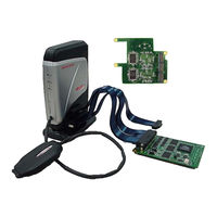
Renesas SuperH SH-4A User Manual (416 pages)
Microcomputer Development Environment System
Brand:
Renesas
| Category:
Computer Hardware
| Size: 4.39 MB
Table of Contents
Table of Contents
19
Section 1 Product Overview
25
Components
29
Emulator Hardware Configuration
30
Emulator Functions
44
Overview
44
Event Detection Functions
48
Trace Functions
51
Break Function
59
Probe Function
60
Peripheral I/O Analyzer Functions
60
Performance Measurement Function
61
Coverage Function
75
Memory Access Functions
76
Stack Trace Function
78
User-Interrupt Open Function During User Program Break
78
Online Help
78
Environmental Conditions
79
Section 2 Setting up the Emulator
81
Flow Chart before Using the Emulator
81
Installing Debugger
82
CD-R
82
Connecting the Optional Units to the Emulator Main Unit Case
83
Connecting the E200F Trace Unit to the User System
83
Connecting the E200F Peripheral I/O Analyzer Unit to the User System
86
Connecting the E200F Expansion Profiling Unit to the Main Unit Case
87
Connecting the AC Adapter to the Emulator Main Unit Case
93
Connecting the Emulator to the Host Machine
94
Connecting the Emulator to the User System
96
Connecting the E200F H-UDI/AUD Probe to the User System
97
Connecting System Ground
100
Changing the Settings
101
Changing the Functions When Using the E200F Main Unit
102
Changing the Functions When Using the External Bus Trace Unit
103
Changing the Functions When Using the Expansion Profiling Unit
104
Changing the Monitoring Function
105
Section 3 Hardware Specifications
107
List of Specifications
107
Interface Circuits in the Emulator
107
Reducing EMI Noise
112
Diagnostic Procedure
113
Installing the Diagnostic Program
113
Executing the Diagnostic Program
113
Creating a Log File
117
Section 4 Preparations for Debugging
119
System Check
119
Method for Activating High-Performance Embedded Workshop
127
Creating the New Workspace (Toolchain Not Used)
128
Creating the New Workspace (Toolchain Used)
132
Selecting an Existing Workspace
137
Setting at Emulator Activation
139
Debug Sessions
141
Selecting a Session
141
Adding and Removing Sessions
142
Saving Session Information
145
Connecting the Emulator
146
Reconnecting the Emulator
147
Ending the Emulator
148
Uninstalling the Emulator's Software
149
Section 5 Debugging
155
Setting the Environment for Emulation
155
Opening the [Configuration] Dialog Box
155
General] Page
156
Main Board] Page
159
Bus Board] Page
161
Option Board] Page
165
Downloading to the Flash Memory
167
Opening the [Memory Mapping] Dialog Box
169
Changing the Memory Map Setting
171
Downloading a Program
172
Viewing the Source Code
173
Viewing the Assembly-Language Code
178
Modifying the Assembly-Language Code
179
Viewing a Specific Address
180
Viewing the Current Program Counter Address
180
Displaying Memory Contents in Realtime
181
Opening the [Monitor] Window
182
Changing the Monitor Settings
184
Temporarily Stopping Update of the Monitor
185
Deleting the Monitor Settings
185
Monitoring Variables
185
Hiding the [Monitor] Window
187
Managing the [Monitor] Window
188
Viewing the Current Status
189
Reading and Displaying the Emulator Information Regularly
190
Opening the [Extended Monitor] Window
190
Selecting Items to be Displayed
191
Using the Eventpoints
192
PC Breakpoints
192
Eventpoints
192
Opening the [Event] Window
194
Setting PC Breakpoints
195
Setting Onchip Eventpoints
197
Setting AUD Eventpoints
206
Setting BUS Eventpoints
223
Setting Other Eventpoints
233
Editing Breakpoint or Eventpoint
238
Enabling Breakpoint or Eventpoint
238
Disabling Breakpoint or Eventpoint
238
Deleting Breakpoint or Eventpoint
238
Deleting All Breakpoints or Eventpoints
238
Viewing the Source Line for Breakpoints or Eventpoints
238
Viewing the Trace Information
239
Opening the [Internal/Aud/Usermemory Trace] Window
239
Opening the [BUS/MFI Trace] Window
247
Hiding the [Trace] Column
250
Searching for a Trace Record
251
Clearing the Trace Information
258
Saving the Trace Information in a File
258
Viewing the [Source] Window
258
Trimming the Source
258
Temporarily Stopping Trace Acquisition
259
Extracting Records from the Acquired Information
259
Analyzing Statistical Information
266
Extracting Function Calls from the Acquired Trace Information
268
Analyzing Performance
269
Opening the [Onchip Performance Analysis] Window
269
Opening the [AUD Performance Analysis] Window
271
Opening the [BUS Performance Analysis] Window
274
Hiding the Column
278
Starting Performance Data Acquisition
278
Deleting a Measurement Condition
278
Deleting All Measurement Conditions
279
Viewing the Profile Information
279
Stack Information Files
279
Profile Information Files
281
Loading Stack Information Files
282
Enabling the Profile
283
Specifying Measuring Mode
283
Executing the Program and Checking the Results
283
List] Sheet
284
Tree] Sheet
285
Profile-Chart] Window
288
Types and Purposes of Displayed Data
288
Creating Profile Information Files
289
Notes
290
Viewing Realtime Profile Information
292
Opening the [Realtime Profile] Window
298
Specifying the Measurement Range
299
Starting Measurement
300
Clearing Measurement Result
300
Deleting Measurement Range
300
Setting the Minimum Unit of the Measurement Time
300
Acquiring Code Coverage
302
Opening the [Code Coverage] Window
302
Displaying a Source File
307
Changing the Address to be Displayed
307
Changing the Coverage Range to be Displayed
308
Clearing the Coverage Information
310
Saving the Coverage Information to a File
310
Loading Coverage Information from a File
311
Updating Coverage Information
311
Preventing Update of Coverage Information
311
Confirmation Request] Dialog Box
312
Displaying Code Coverage Information in the [Editor] Window
314
Synchronizing Multiple Debugging Platforms
315
Distinguishing Two Emulators
316
Section 6 Tutorial
319
Introduction
319
Running the High-Performance Embedded Workshop
320
Setting up the Emulator
320
Setting the [Configuration] Dialog Box
321
Checking the Operation of the Target Memory for Downloading
322
Downloading the Tutorial Program
324
Displaying the Source Program
325
Setting a PC Breakpoint
326
Setting Registers
327
Executing the Program
329
Reviewing Breakpoints
332
Referring to Symbols
333
Viewing Memory
334
Watching Variables
336
Displaying Local Variables
339
Stepping through a Program
340
Executing [Step In] Command
340
Executing [Step Out] Command
342
Executing [Step Over] Command
343
Forced Breaking of Program Executions
344
Break Function
345
PC Break Function
345
Break Function by an Eventpoint
350
Setting the Break by an Onchip Eventpoint
350
Setting the Sequential Onchip Eventpoint
355
Trace Functions
359
Displaying the [Internal/Aud/Usermemory Trace] Window
361
Displaying the [BUS/MFI Trace] Window
376
MMU Support
380
Stack Trace Function
383
Download Function to the Flash Memory Area
385
What Next
391
Section 7 Troubleshooting
393
Section 8 Maintenance and Guarantee
395
User Registration
395
Maintenance
395
Guarantee
395
Repair Provisions
396
Repair with Extra-Charge
396
Replacement with Extra-Charge
396
Expiration of the Repair Period
396
Transportation Fees at Sending Your Product for Repair
396
How to Make a Request for Repair
397
Appendix A Menus
399
Appendix B Command-Line Functions
403
Appendix C Notes on High-Performance Embedded Workshop
405
Appendix D Repair Request Sheet
409
Advertisement
Related Products
Renesas SH4AL-DSP
Renesas SH7211
Renesas SH7286
Renesas SH2/7137
Renesas SuperHTM Family SH7125 Series
Renesas Single-Chip Microcomputer SH7203
Renesas SH7616
Renesas SuperH RISC SH7040 Series
Renesas F-ZTAT SH7050F
Renesas SH7269
Renesas Categories
Computer Hardware
Motherboard
Microcontrollers
Adapter
Switch
More Renesas Manuals
Login
Sign In
OR
Sign in with Facebook
Sign in with Google
Upload manual
Upload from disk
Upload from URL