Sign In
Upload
Manuals
Brands
Lenze Manuals
Inverter
i950 Series
Lenze i950 Series Manuals
Manuals and User Guides for Lenze i950 Series. We have
10
Lenze i950 Series manuals available for free PDF download: Manual, Commissioning Manual, Mounting And Switch-On Instructions, Project Planning, Mounting Instructions
Lenze i950 Series Commissioning Manual (496 pages)
Servo Inverters
Brand:
Lenze
| Category:
Inverter
| Size: 5 MB
Table of Contents
Table of Contents
3
1 About this Document
15
Document Description
15
Further Documents
15
Notations and Conventions
16
2 Safety Instructions
17
Basic Safety Instructions
17
Application as Directed
17
Residual Hazards
18
3 Product Information
19
Identification of the Products
19
Product Codes
19
Nameplates
20
Features
21
4 Commissioning
27
Important Notes
27
Operating Interfaces
28
Engineering Tool »EASY Starter
29
Generate a Connection between Inverter and »EASY Starter
30
General Information on Parameter Setting
31
Addressing of the Parameters
31
Structure of the Parameter Descriptions
31
Parameter Overview Lists
31
Favourites
32
Configuring the "Favourites
32
Commissioning
35
Saving the Parameter Settings
36
Save Parameter Settings with »EASY Starter
36
5 Basic Setting
37
Device Name
37
Mains Voltage
37
Function Assignment of the Inputs and Outputs (Default Setting)
37
Motor Data
38
Select Motor from Motor Catalogue
39
Manual Setting of the Motor Data
41
Motor Control Mode
44
6 Technology Application (TA) Basic Settings
45
Kinematic Settings
46
Mass Inertia (Load/Motor)
46
Torque Feedforward Control
46
Motor/Encoder Mounting Direction
46
Motor/Encoder Gearbox Ratio
47
Motor/Encoder Feed Constant
49
Motor/Encoder Travel Ranges and Cycle Length
50
Virtual Mode
52
Motion Settings
53
Quick Stop
53
Halt
54
Following Error Monitoring
54
Target Position Detection
55
Motor/Encoder Standstill Detection
55
Conditioning of the Encoder Signal
55
Behaviour in the Event of Inverter Disable
56
Control Modes
57
Manual Jog (Inching Mode)
57
Homing
58
Homing Modes
60
Digital Input for Reference Switch
69
Motor/Encoder Behaviour after Mains Switching
69
Limitations
70
Torque Limits
70
Maximum Values for Travel Profiles
71
Hardware Limit Switches
72
Software Limit Switches
73
Safety Limits
74
Status Signals
76
Defining Control Sources
78
Source of Quick Stop
78
Source of Error Reset
78
Source of Digital Output 1
79
Source of Monitoring Signal
80
System Bus Communication
81
Inputs
81
Outputs
81
Master Value Output
82
Source of Touch Probe Time Stamp
83
Distribution of the Master Values by the Master
84
Example: System Bus Master Is Master Value Master
85
Example: System Bus Slave Is Master Value Master
86
Example: Using Time Stamp of Another Axis
87
7 Configuring the "Winder Dancer" TA
88
Commissioning
91
Control Settings
98
Defining the Winding Direction
99
Defining the Material Feeding
101
Source Selection for Control Signals
102
Source for Line Speed
103
Source for Circumferential Speed
104
Source for Start Diameter
104
Source for Set Dancer Position
105
Source for Actual Dancer Position
105
Source for Dancer Control Correction Value
106
Interface
107
Control Signals
108
Status Signals
109
Simulation of the Interface
112
Manual Jog of Winding Shaft
114
Synchronisation to Line Speed
116
Diameter Calculation
117
Loading the Start Diameter
120
Diameter Adjustment
121
Dancer Motion Compensation
122
Diameter Estimation before Dancer Motion
124
Scaling the Actual Dancer Position
127
Dancer Control
129
Reduced Controller Dynamics in Case of System Deviations
131
Dancer Limit Position Teach-In Function
132
Acceleration Compensation
133
Identifying Moments of Inertia
135
Identifying the Constant Moment of Inertia
136
Identifying the Maximum Moment of Inertia
137
Terminating the Identification
137
Calculating the Maximum Moment of Inertia
138
Adapting the Speed Controller Gain
139
Signal Flow
142
Monitoring
144
Web Break Monitoring
144
Monitoring Based on the Change in Diameter
144
Monitoring Based on the Dancer Position
146
Monitoring the Dancer Position
147
Diameter Hold
148
Speed Limitation from the Master
149
8 Start, Stop and Rotating Direction Commands
151
Control Selection
151
9 Configure Position Control
152
Basic Setting
153
Following Error Detection and In-Position Detection
154
Interpolation
155
Operating Mode "Cia 402 Cyclic Sync Position Mode (Csp)
156
Default Mapping
156
Signal Flow
157
Control Commands and Status Information
159
Process Input Data (Cia 402 Objects)
160
Process Output Data (Cia 402 Objects)
161
Monitoring the Position Error
162
Position Detection with Touch Probe (TP)
163
Default Mapping
163
General Mode of Operation
164
Filtering of the Touch Probe Signal
164
Compensation of Runtime Delays
165
Touch Probe Control Word
166
Touch Probe Status Word
166
Extension for the Digital Inputs DI3 and DI4
167
Detected Time Stamp and Positions
167
Setpoint Diagnostics
168
10 Configure Speed Control
169
Basic Setting
169
Operating Mode "Cia 402 Velocity Mode (Vl)
170
Default Mapping
170
Signal Flow (Servo Control)
171
Signal Flow (V/F Characteristic Control)
173
Operating Mode "Cia 402 Cyclic Sync Velocity Mode (Csv)
175
Default Mapping
175
Signal Flow (Servo Control)
176
Signal Flow (V/F Characteristic Control)
178
Control Commands and Status Information
180
Process Input Data (Cia 402 Objects)
181
Process Output Data (Cia 402 Objects)
183
Monitoring the Speed Deviation
184
Advertisement
Lenze i950 Series Manual (500 pages)
Servo inverters. Commissioning.
Brand:
Lenze
| Category:
Inverter
| Size: 5 MB
Table of Contents
Table of Contents
3
1 About this Document
15
Document Description
15
Further Documents
15
Notations and Conventions
16
2 Safety Instructions
17
Basic Safety Instructions
17
Application as Directed
17
Residual Hazards
18
3 Product Information
19
Identification of the Products
19
Product Codes
19
Nameplates
20
Features
21
4 Commissioning
27
Important Notes
27
Operating Interfaces
28
Engineering Tool »EASY Starter
29
Generate a Connection between Inverter and »EASY Starter
30
General Information on Parameter Setting
31
Addressing of the Parameters
31
Structure of the Parameter Descriptions
31
Parameter Overview Lists
31
Favourites
32
Configuring the "Favourites
32
Commissioning
35
Saving the Parameter Settings
36
Save Parameter Settings with »EASY Starter
36
5 Basic Setting
37
Device Name
37
Mains Voltage
37
Function Assignment of the Inputs and Outputs (Default Setting)
37
Motor Data
38
Select Motor from Motor Catalogue
39
Manual Setting of the Motor Data
41
Motor Control Mode
44
6 Technology Application (TA) Basic Settings
45
Kinematic Settings
46
Mass Inertia (Load/Motor)
46
Torque Feedforward Control
46
Motor/Encoder Mounting Direction
46
Motor/Encoder Gearbox Ratio
47
Motor/Encoder Feed Constant
49
Motor/Encoder Travel Ranges and Cycle Length
50
Virtual Mode
52
Motion Settings
53
Quick Stop
53
Halt
54
Following Error Monitoring
54
Target Position Detection
55
Motor/Encoder Standstill Detection
55
Conditioning of the Encoder Signal
55
Behaviour in the Event of Inverter Disable
56
Control Modes
57
Manual Jog (Inching Mode)
58
Homing
59
Homing Modes
61
Digital Input for Reference Switch
70
Motor/Encoder Behaviour after Mains Switching
70
Limitations
71
Torque Limits
71
Maximum Values for Travel Profiles
72
Hardware Limit Switches
73
Software Limit Switches
75
Safety Limits
76
Status Signals
78
Defining Control Sources
80
Source of Quick Stop
80
Source of Error Reset
80
Source of Digital Output 1
81
Source of Monitoring Signal
81
System Bus Communication
82
Inputs
82
Outputs
82
Master Value Output
83
Source of Touch Probe Time Stamp
84
Distribution of the Master Values by the Master
85
Example: System Bus Master Is Master Value Master
86
Example: System Bus Slave Is Master Value Master
87
Example: Using Time Stamp of Another Axis
88
7 Configuring the "Sync and Correction" TA
89
Control Settings
90
Interface
91
Control Signals
92
Status Signals
93
Simulation of the Interface
95
Assignment of Control Signals and Status Signals
97
Master Value Sources
100
System Bus
101
Feedback System for the Technology Application
102
Virtual Master
104
Simulation of the Virtual Master
111
Speed Via Analog Input 1
112
External Master Values
113
Position Trimming and Position Offset
116
Position Offset from Master
120
Position Synchronism
121
Position Clutch
123
Path-Controlled Clutch
124
Time-Controlled Clutch
126
Travel Profile-Based Clutch
128
Asynchronous Clutch
133
Master Value Correction (Register Control)
134
Mark Window and Mark Register
137
Mark Failure Detection
139
Position Correction
140
Gearbox Factor Correction
142
Tool Correction
143
Mark Window and Mark Register
144
Mark Failure Detection
145
Position Correction
146
Signal Flow
147
Master Value Selection and Master Value Correction
147
Position Synchronism
151
Tool Correction
151
8 Start, Stop and Rotating Direction Commands
153
Control Selection
153
9 Configure Position Control
154
Basic Setting
155
Following Error Detection and In-Position Detection
156
Interpolation
157
Operating Mode "Cia 402 Cyclic Sync Position Mode (Csp)
158
Default Mapping
158
Signal Flow
159
Control Commands and Status Information
161
Process Input Data (Cia 402 Objects)
162
Process Output Data (Cia 402 Objects)
163
Monitoring the Position Error
164
Position Detection with Touch Probe (TP)
165
Default Mapping
165
General Mode of Operation
166
Filtering of the Touch Probe Signal
166
Compensation of Runtime Delays
167
Touch Probe Control Word
168
Touch Probe Status Word
168
Extension for the Digital Inputs DI3 and DI4
169
Detected Time Stamp and Positions
169
Setpoint Diagnostics
170
10 Configure Speed Control
171
Basic Setting
171
Operating Mode "Cia 402 Velocity Mode (Vl)
172
Default Mapping
172
Signal Flow (Servo Control)
173
Signal Flow (V/F Characteristic Control)
175
Operating Mode "Cia 402 Cyclic Sync Velocity Mode (Csv)
177
Default Mapping
177
Signal Flow (Servo Control)
178
Signal Flow (V/F Characteristic Control)
180
Control Commands and Status Information
182
Process Input Data (Cia 402 Objects)
183
Process Output Data (Cia 402 Objects)
185
Monitoring the Speed Deviation
186
Lenze i950 Series Commissioning Manual (484 pages)
Servo Inverters
Brand:
Lenze
| Category:
Inverter
| Size: 21 MB
Table of Contents
Table of Contents
3
1 About this Document
15
Document Description
15
Further Documents
15
Notations and Conventions
16
2 Safety Instructions
17
Basic Safety Instructions
17
Application as Directed
17
Residual Hazards
18
3 Product Information
19
Identification of the Products
19
Product Codes
19
Nameplates
20
Features
21
4 Commissioning
27
Important Notes
27
Operating Interfaces
28
Engineering Tool »EASY Starter
29
Generate a Connection between Inverter and »EASY Starter
30
General Information on Parameter Setting
31
Addressing of the Parameters
31
Structure of the Parameter Descriptions
31
Parameter Overview Lists
31
Favourites
32
Configuring the "Favourites
32
Commissioning
35
Saving the Parameter Settings
36
Save Parameter Settings with »EASY Starter
36
5 Basic Setting
37
Device Name
37
Mains Voltage
37
Function Assignment of the Inputs and Outputs (Default Setting)
37
Motor Data
38
Select Motor from Motor Catalogue
39
Manual Setting of the Motor Data
41
Motor Control Mode
43
6 Technology Application (TA) Basic Settings
44
Kinematic Settings
45
Mass Inertia (Load/Motor)
45
Torque Feedforward Control
45
Motor/Encoder Mounting Direction
45
Motor/Encoder Gearbox Ratio
46
Motor/Encoder Feed Constant
48
Motor/Encoder Travel Ranges and Cycle Length
49
Virtual Mode
51
Motion Settings
52
Quick Stop
52
Halt
53
Following Error Monitoring
53
Target Position Detection
54
Motor/Encoder Standstill Detection
54
Conditioning of the Encoder Signal
54
Behaviour in the Event of Inverter Disable
55
Control Modes
56
Manual Jog (Inching Mode)
57
Homing
58
Homing Modes
60
Digital Input for Reference Switch
69
Motor/Encoder Behaviour after Mains Switching
69
Limitations
70
Torque Limits
70
Maximum Values for Travel Profiles
71
Hardware Limit Switches
72
Software Limit Switches
73
Safety Limits
74
Status Signals
76
Defining Control Sources
78
Source of Quick Stop
78
Source of Error Reset
78
Source of Digital Output 1
79
Source of Monitoring Signal
80
System Bus Communication
81
Inputs
81
Outputs
82
Master Value Output
82
Source of Touch Probe Time Stamp
83
Distribution of the Master Values by the Master
84
Example: System Bus Master Is Master Value Master
85
Example: System Bus Slave Is Master Value Master
86
Example: Using Time Stamp of Another Axis
87
7 Configuring the "Winder Tension" TA
88
Commissioning
90
Control Settings
95
Defining the Winding Direction
96
Defining the Material Feeding
98
Source Selection for Control Signals
99
Source for Line Speed
100
Source for Start Diameter
101
Source for Set Tensile Force
101
Source for Actual Tensile Force
102
Source for Tensile Force Controller Influence
102
Interface
103
Control Signals
103
Status Signals
104
Simulation of the Interface
106
Manual Jog of Winding Shaft
107
Synchronisation to Line Speedsynchronisation to Line Speed
109
Diameter Calculation
110
Loading the Start Diameter
113
Diameter Adjustment
114
Friction Compensation
115
Identifying the Friction Characteristic
117
Friction Characteristic
119
Tension Control Closed Loop and Open Loop
120
Torque-Based Tension Control Open Loop
122
Torque-Based Tension Control Closed Loop
123
Tensile Force Characteristic
125
Diameter-Dependent Tensile Force Reduction
126
Reduced Controller Dynamics in Case of System Deviations
127
Acceleration Compensation
128
Identifying the Moments of Inertia
130
Identifying the Constant Moment of Inertia
131
Identifying the Maximum Moment of Inertia
132
Terminating the Identification
132
Calculating the Maximum Moment of Inertia
133
Adapting the Speed Controller Gain
134
Signal Flow
137
Monitoring
139
Web Break Monitoring
139
Speed Limitation
140
Speed Limitation in Case of Web Break
141
Speed Limitation for Unwinder
141
Diameter Hold
142
Speed Limitation by Master
143
8 Start, Stop and Rotating Direction Commands
145
Control Selection
145
9 Configure Position Control
146
Basic Setting
147
Following Error Detection and In-Position Detection
148
Interpolation
149
Operating Mode "Cia 402 Cyclic Sync Position Mode (Csp)
150
Default Mapping
150
Signal Flow
151
Control Commands and Status Information
153
Process Input Data (Cia 402 Objects)
153
Process Output Data (Cia 402 Objects)
154
Monitoring the Position Error
155
Position Detection with Touch Probe (TP)
156
Default Mapping
156
General Mode of Operation
157
Filtering of the Touch Probe Signal
157
Compensation of Runtime Delays
158
Touch Probe Control Word
159
Touch Probe Status Word
159
Extension for the Digital Inputs DI3 and DI4
160
Detected Time Stamp and Positions
161
Setpoint Diagnostics
161
10 Configure Speed Control
162
Basic Setting
162
Operating Mode "Cia 402 Velocity Mode (Vl)
163
Default Mapping
163
Signal Flow (Servo Control)
164
Signal Flow (V/F Characteristic Control)
166
Operating Mode "Cia 402 Cyclic Sync Velocity Mode (Csv)
168
Default Mapping
168
Signal Flow (Servo Control)
169
Signal Flow (V/F Characteristic Control)
171
Control Commands and Status Information
173
Process Input Data (Cia 402 Objects)
174
Process Output Data (Cia 402 Objects)
175
Monitoring the Speed Deviation
176
Advertisement
Lenze i950 Series Commissioning Manual (472 pages)
Servo Inverters
Brand:
Lenze
| Category:
Inverter
| Size: 4 MB
Table of Contents
Table of Contents
3
1 About this Document
15
Document Description
15
Further Documents
15
Notations and Conventions
16
2 Safety Instructions
17
Basic Safety Instructions
17
Application as Directed
17
Residual Hazards
18
3 Product Information
19
Identification of the Products
19
Product Codes
19
Nameplates
20
Features
21
4 Commissioning
27
Important Notes
27
Operating Interfaces
28
Engineering Tool »EASY Starter
29
Generate a Connection between Inverter and »EASY Starter
30
General Information on Parameter Setting
31
Addressing of the Parameters
31
Structure of the Parameter Descriptions
31
Parameter Overview Lists
31
Favourites
32
Configuring the "Favourites
32
Commissioning
35
Saving the Parameter Settings
36
Save Parameter Settings with »EASY Starter
36
5 Basic Setting
37
Device Name
37
Mains Voltage
37
Function Assignment of the Inputs and Outputs (Default Setting)
37
Motor Data
38
Select Motor from Motor Catalogue
39
Manual Setting of the Motor Data
41
Motor Control Mode
44
6 Technology Application (TA) Basic Settings
45
Kinematic Settings
46
Mass Inertia (Load/Motor)
46
Torque Feedforward Control
46
Motor/Encoder Mounting Direction
46
Motor/Encoder Gearbox Ratio
47
Motor/Encoder Feed Constant
49
Motor/Encoder Travel Ranges and Cycle Length
50
Virtual Mode
52
Motion Settings
53
Quick Stop
53
Halt
54
Following Error Monitoring
54
Target Position Detection
55
Motor/Encoder Standstill Detection
55
Conditioning of the Encoder Signal
55
Behaviour in the Event of Inverter Disable
56
Control Modes
57
Manual Jog (Inching Mode)
58
Homing
59
Homing Modes
61
Digital Input for Reference Switch
70
Motor/Encoder Behaviour after Mains Switching
70
Limitations
71
Torque Limits
71
Maximum Values for Travel Profiles
72
Hardware Limit Switches
73
Software Limit Switches
75
Safety Limits
76
Status Signals
78
Defining Control Sources
80
Source of Quick Stop
80
Source of Error Reset
80
Source of Digital Output 1
81
Source of Monitoring Signal
82
System Bus Communication
84
Inputs
84
Outputs
84
Master Value Output
85
Source of Touch Probe Time Stamp
86
Distribution of the Master Values by the Master
87
Example: System Bus Master Is Master Value Master
88
Example: System Bus Slave Is Master Value Master
89
Example: Using Time Stamp of Another Axis
90
7 Configuring the "Electronic Gearbox" TA
91
Control Settings
92
Interface
93
Control Signals
94
Status Signals
95
Simulation of the Interface
96
Assignment of Control Signals and Status Signals
97
Master Value Sources
99
System Bus
100
Feedback System for the Technology Application
101
Virtual Master
103
Simulation of the Virtual Master
110
Speed Via Analog Input 1
111
External Master Values
112
External Torque Limitation
115
Velocity Synchronization
117
Clutching
119
Clutching with Basic Speed
120
Connecting the Velocity Offset
122
Position Trimming
124
Signal Flow
127
8 Start, Stop and Rotating Direction Commands
129
Control Selection
129
9 Configure Position Control
130
Basic Setting
131
Following Error Detection and In-Position Detection
132
Interpolation
133
Operating Mode "Cia 402 Cyclic Sync Position Mode (Csp)
134
Default Mapping
134
Signal Flow
135
Control Commands and Status Information
137
Process Input Data (Cia 402 Objects)
138
Process Output Data (Cia 402 Objects)
139
Monitoring the Position Error
140
Position Detection with Touch Probe (TP)
141
Default Mapping
141
General Mode of Operation
142
Filtering of the Touch Probe Signal
142
Compensation of Runtime Delays
143
Touch Probe Control Word
144
Touch Probe Status Word
144
Extension for the Digital Inputs DI3 and DI4
145
Detected Time Stamp and Positions
145
Setpoint Diagnostics
146
10 Configure Speed Control
147
Basic Setting
147
Operating Mode "Cia 402 Velocity Mode (Vl)
148
Default Mapping
148
Signal Flow (Servo Control)
149
Signal Flow (V/F Characteristic Control)
151
Operating Mode "Cia 402 Cyclic Sync Velocity Mode (Csv)
153
Default Mapping
153
Signal Flow (Servo Control)
154
Signal Flow (V/F Characteristic Control)
156
Control Commands and Status Information
158
Process Input Data (Cia 402 Objects)
159
Process Output Data (Cia 402 Objects)
161
Monitoring the Speed Deviation
162
11 Configuring the Torque Control
163
Basic Setting
164
Torque Limits
165
Speed Limitation
166
Operating Mode "Cia 402 Cyclic Sync Torque Mode (Cst)
167
Default Mapping
167
Signal Flow
168
Control Commands and Status Information
170
Process Input Data (Cia 402 Objects)
171
Process Output Data (Cia 402 Objects)
173
Setpoint Diagnostics
174
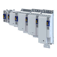
Lenze i950 Series Mounting And Switch-On Instructions (188 pages)
Cabinet inverter
Brand:
Lenze
| Category:
Inverter
| Size: 7 MB
Table of Contents
Deutsch
5
Table of Contents
5
Über dieses Dokument
8
Weiterführende Dokumente
8
Schreibweisen und Konventionen
9
Sicherheitshinweise
10
Grundlegende Sicherheitshinweise
10
Bestimmungsgemäße Verwendung
11
Vorhersehbarer Fehlgebrauch
11
Restgefahren
12
Produktinformation
14
Identifizierung der Produkte
14
Produktcodes
14
Typenschilder
15
Ausstattung
16
Lizenzinformation
22
Mechanische Installation
23
Vorbereitung
23
Abmessungen
25
Elektrische Installation
38
Wichtige Hinweise
38
EMV-Gerechte Installation
38
Anschluss nach UL
39
Wichtige Hinweise
39
Absicherungsdaten
42
Branch Circuit Protection (BCP)
42
DC Circuit Protection
45
Netzanschluss
46
1-Phasiger Netzanschluss 230/240 V
46
Anschlusspläne
46
Klemmendaten
47
Absicherungsdaten
47
3-Phasiger Netzanschluss 230/240 V
48
Anschlusspläne
48
Klemmendaten
49
Absicherungsdaten
50
Anschlusspläne
51
3-Phasiger Netzanschluss 400 V
52
Klemmendaten
52
Absicherungsdaten
53
3-Phasiger Netzanschluss 480 V
54
Anschlusspläne
54
Klemmendaten
55
Absicherungsdaten
56
Anschluss an das IT-Netz
57
Anschluss Versorgungsspannung
61
Anschluss Motorhaltebremse
62
Anschluss Bremswiderstand
64
Steueranschlüsse
66
Anschluss Motorgeber
67
Anschluss Lastgeber/Leitgeber
67
Anschluss Einkabeltechnologie (OCT) über HIPERFACE DSL
68
Netzwerke
70
Ethercat
70
Ethernet/Ip
71
Profinet
73
On-Board-Ethercat
74
Funktionale Sicherheit
75
Basic Safety - STO
76
Anschlussplan
77
Klemmendaten
78
Extended Safety
79
Anschlussplan
80
Klemmendaten
81
Inbetriebnahme
82
Wichtige Hinweise
82
Bedienschnittstellen
83
Engineering Tool "EASY Starter
84
Verbindung zwischen Inverter und "EASY Starter" Aufbauen
85
Inbetriebnahme Durchführen
85
Parametereinstellungen Speichern
86
Parametereinstellungen mit dem "EASY Starter" Speichern
86
Diagnose und Störungsbeseitigung
87
LED-Statusanzeigen
87
Technische Daten
88
Normen und Einsatzbedingungen
88
Konformitäten und Approbationen
88
Personenschutz und Geräteschutz
88
Angaben zur EMV
88
Motoranschluss
89
Umweltbedingungen
89
Netzbedingungen
89
1-Phasiger Netzanschluss 230/240 V
90
Bemessungsdaten
90
3-Phasiger Netzanschluss 230/240 V
91
Bemessungsdaten
91
3-Phasiger Netzanschluss 400 V
92
Bemessungsdaten
92
3-Phasiger Netzanschluss 480 V
94
Bemessungsdaten
94
Umwelthinweise und Recycling
96
Lenze i950 Series Mounting And Switch-On Instructions (184 pages)
servo inverter
Brand:
Lenze
| Category:
Inverter
| Size: 6 MB
Table of Contents
Deutsch
5
Table of Contents
5
Über dieses Dokument
8
Weiterführende Dokumente
8
Schreibweisen und Konventionen
9
Sicherheitshinweise
10
Grundlegende Sicherheitshinweise
10
Bestimmungsgemäße Verwendung
11
Vorhersehbarer Fehlgebrauch
11
Restgefahren
12
Produktinformation
14
Ausstattung
14
Identifizierung der Produkte
20
Produktcodes
20
Typenschilder
21
Lizenzinformation
22
Mechanische Installation
23
Vorbereitung
23
Abmessungen
24
Elektrische Installation
37
Wichtige Hinweise
37
EMV-Gerechte Installation
37
Anschluss nach UL
38
Wichtige Hinweise
38
Absicherungsdaten
41
Branch Circuit Protection (BCP)
41
DC Circuit Protection
44
Netzanschluss
45
1-Phasiger Netzanschluss 230/240 V
45
Anschlusspläne
45
Klemmendaten
46
Absicherungsdaten
47
3-Phasiger Netzanschluss 230/240 V
48
Anschlusspläne
48
Klemmendaten
49
Absicherungsdaten
50
Anschlusspläne
51
3-Phasiger Netzanschluss 400 V
52
Klemmendaten
52
Absicherungsdaten
53
3-Phasiger Netzanschluss 480 V
54
Anschlusspläne
54
Klemmendaten
55
Absicherungsdaten
56
Anschluss an das IT-Netz
57
Anschluss Versorgungsspannung
61
Anschluss Motorhaltebremse
62
Anschluss Bremswiderstand
64
Steueranschlüsse
65
Anschluss Motorgeber
66
Anschluss Lastgeber/Leitgeber
66
Anschluss Einkabeltechnologie (OCT) über HIPERFACE DSL
67
Netzwerke
69
Onboard Ethercat
69
Ethercat
69
Ethernet/Ip
69
Powerlink
70
Funktionale Sicherheit
71
Basic Safety - STO
72
Anschlussplan
72
Klemmendaten
73
Extended Safety
74
Anschlussplan
75
Klemmendaten
76
Inbetriebnahme
77
Wichtige Hinweise
77
Bedienschnittstellen
78
Engineering Tool "EASY Starter
79
Verbindung zwischen Umrichter und "EASY Starter" Aufbauen
80
Inbetriebnahme Durchführen
80
Parametereinstellungen Speichern
81
Parametereinstellungen mit dem "EASY Starter" Speichern
81
Diagnose und Störungsbeseitigung
82
LED-Statusanzeigen
82
Technische Daten
83
Normen und Einsatzbedingungen
83
Konformitäten und Approbationen
83
Personenschutz und Geräteschutz
83
Angaben zur EMV
83
Motoranschluss
84
Umweltbedingungen
84
Netzbedingungen
84
1-Phasiger Netzanschluss 230/240 V
85
Bemessungsdaten
85
3-Phasiger Netzanschluss 230/240 V
86
Bemessungsdaten
86
3-Phasiger Netzanschluss 400 V
87
Bemessungsdaten
87
3-Phasiger Netzanschluss 480 V
89
Bemessungsdaten
89
Ökodesign-Verordnung
91
Umwelthinweise und Recycling
93
Lenze i950 Series Project Planning (184 pages)
Cabinet Inverter
Brand:
Lenze
| Category:
Inverter
| Size: 7 MB
Table of Contents
Table of Contents
3
About this Document
9
Document Description
9
Further Documents
9
Notations and Conventions
10
Product Information
11
Product Description
11
Identification of the Products
14
Features
15
The Modular System
21
Topologies / Network
21
Technology Applications (TA)
22
Overview
22
Cia 402 Advanced" Technology Application
22
Electronic Gearbox" Technology Application
22
Speed Control" Technology Application
23
Sync and Correction" Technology Application
23
Winder Dancer" Technology Application
23
Winder Tension" Technology Application
23
One Cable Technology (OCT) Via HIPERFACE DSL
24
Information on Project Planning
25
Project Planning Process
25
Operation in Motor and Generator Mode
25
Overcurrent Operation
26
Safety Instructions
27
Basic Safety Instructions
27
Application as Directed
27
Handling
28
Residual Hazards
30
Control Cabinet Structure
32
Arrangement of Components
32
Cables
33
Earthing Concept
33
EMC-Compliant Installation
34
Information on Mechanical Installation
36
Important Notes
36
Preparation
37
Functional Safety
38
Information on Electrical Installation
40
Important Notes
40
Preparation
42
Connection According to UL
43
Mains Connection
46
3-Phase Mains Connection 400 V
47
3-Phase Mains Connection 480 V
48
Motor Connection
49
Connection to the IT System
50
Supply Voltage Connection
53
Connection of Motor Temperature Monitoring
54
Motor Holding Brake Connection
55
Brake Resistor Connection
57
DC-Bus Connection
58
Control Connections
58
Motor Encoder Connection
58
Load Encoder/Master Encoder Connection
58
Connection of One Cable Technology (OCT) Via HIPERFACE DSL
59
Networks
60
Ethercat
60
Profinet
60
Ethercat System Bus
61
Functional Safety
62
Basic Safety - STO
63
Connection Diagram
64
Terminal Data
65
Extended Safety
66
Connection Diagram
67
Terminal Data
68
Lenze i950 Series Mounting And Switch-On Instructions (144 pages)
Brand:
Lenze
| Category:
Inverter
| Size: 6 MB
Table of Contents
Deutsch
5
Table of Contents
5
Über dieses Dokument
7
Dokumentbeschreibung
7
Weiterführende Dokumente
7
Schreibweisen und Konventionen
8
Sicherheitshinweise
9
Grundlegende Sicherheitshinweise
9
Bestimmungsgemäße Verwendung
9
Handhabung
10
Restgefahren
10
Lizenzinformation
11
Produktinformation
12
Identifizierung der Produkte
12
Produktcodes
12
Typenschilder
13
Ausstattung
14
Mechanische Installation
21
Abmessungen
21
Elektrische Installation
33
Wichtige Hinweise
33
Netzanschluss
36
Anschlusspläne
36
3-Phasiger Netzanschluss 400 V
38
Klemmendaten
38
Absicherungsdaten
40
3-Phasiger Netzanschluss 480 V
42
Anschlusspläne
42
Klemmendaten
43
Absicherungsdaten
44
Anschluss an das IT-Netz
47
Steueranschlüsse
51
Netzwerke
52
Profinet
52
Systembus Ethercat
53
Funktionale Sicherheit
54
Basic Safety - STO
55
Anschlussplan
55
Klemmendaten
56
Extended Safety
57
Anschlussplan
58
Klemmendaten
60
Inbetriebnahme
61
Wichtige Hinweise
61
Bedienschnittstellen
62
Engineering Tool "EASY Starter
63
Verbindung zwischen Inverter und "EASY Starter" Aufbauen
64
Allgemeines zur Parametrierung
65
Favoriten
65
Favoriten Konfigurieren
65
Inbetriebnahme Durchführen
66
Parametereinstellungen Speichern
67
Parametereinstellungen mit dem "EASY Starter" Speichern
67
Diagnose und Störungsbeseitigung
68
LED-Statusanzeigen
68
Technische Daten
69
Normen und Einsatzbedingungen
69
Konformitäten/Approbationen
69
Personenschutz und Geräteschutz
69
Angaben zur EMV
69
Motoranschluss
70
Umweltbedingungen
70
Netzbedingungen
70
3-Phasiger Netzanschluss 400 V
71
Bemessungsdaten
71
3-Phasiger Netzanschluss 480 V
73
Bemessungsdaten
73
Lenze i950 Series Manual (32 pages)
Teachware Application case (3-axis)
Brand:
Lenze
| Category:
Inverter
| Size: 0 MB
Table of Contents
Deutsch
2
Table of Contents
2
1 Sicherheitshinweise
3
Grundlegende Sicherheitshinweise
3
Restgefahren
3
Bestimmungsgemäße Verwendung
4
Vorhersehbare Fehlanwendung
4
2 Technische Daten
5
Lieferumfang
5
Normen und Einsatzbedingungen
5
Bemessungsdaten
6
3 Inbetriebnahme
7
Vor dem Ersten Einschalten
8
Vorbereitung
8
Einschalten
9
Funktionsprüfung
9
Schaltsystem IO
10
Schaltsystem Safety es
12
Austausch von Netzwerk-Module oder Feedback-Module
14
Anschluss Externe Motoren
14
4 Diagnose und Störungsbeseitigung
15
5 Wartung
15
6 Reparatur
15
7 Entsorgung
15
English
18
1 Safety Instructions
19
Basic Safety Instructions
19
Residual Hazards
19
Application as Directed
20
Foreseeable Misuse
20
2. Technical Data
21
Scope of Supply
21
Standards and Operating Conditions
21
Rating
22
3 Commissioning
23
Before Initial Switch-On
24
Preparation
24
Switch on
25
Functional Test
25
Switching System IO
26
Switching System Safety es
28
Connection of External Motors
30
Replacement of Network Modules or Feedback Modules
30
4 Troubleshooting and Fault Elimination
31
5 Maintenance
31
6 Repair
31
7 Disposal
31
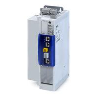
Lenze i950 Series Mounting Instructions (6 pages)
Network module
Brand:
Lenze
| Category:
Control Unit
| Size: 2 MB
Advertisement
Related Products
Lenze i950-Cabinet
Lenze I95AE275F
Lenze I95AE311F
Lenze I95AE175F
Lenze I95AE315F
Lenze I95AE345F
Lenze I95AE375F
Lenze I95AE355F
Lenze I95AE222F
Lenze I95AE411F
Lenze Categories
DC Drives
Control Unit
Inverter
Engine
Controller
More Lenze Manuals
Login
Sign In
OR
Sign in with Facebook
Sign in with Google
Upload manual
Upload from disk
Upload from URL