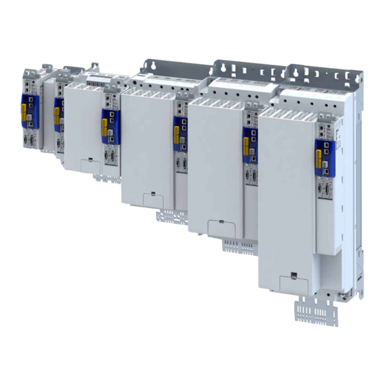
Lenze i950 Commissioning Manual
Servo inverters
Hide thumbs
Also See for i950:
- Manual (500 pages) ,
- Commissioning manual (496 pages) ,
- Mounting and switch-on instructions (188 pages)
Table of Contents
Advertisement
Quick Links
Advertisement
Table of Contents

Related Manuals for Lenze i950


Summary of Contents for Lenze i950
- Page 1 Commissioning EN Inverters i950 servo inverters...
-
Page 3: Table Of Contents
Contents Contents 1 About this document Document description 1.1.1 Further documents Notations and conventions 2 Safety instructions Basic safety instructions Application as directed Residual hazards 3 Product information Identification of the products 3.1.1 Product codes 3.1.2 Nameplates Features 4 Commissioning Important notes Operating interfaces 4.2.1... - Page 4 Contents 6 Technology application (TA) basic settings Kinematic settings 6.1.1 Mass inertia (load/motor) 6.1.2 Torque feedforward control 6.1.3 Motor/encoder mounting direction 6.1.4 Motor/encoder gearbox ratio 6.1.5 Motor/encoder feed constant 6.1.6 Motor/encoder travel ranges and cycle length 6.1.7 Virtual mode Motion settings 6.2.1 Quick stop 6.2.2...
- Page 5 Contents 7 Configuring the "Winder Tension" TA Commissioning Control settings 7.2.1 Defining the winding direction 7.2.2 Defining the material feeding Source selection for control signals 7.3.1 Source for line speed 7.3.2 Source for start diameter 7.3.3 Source for set tensile force 7.3.4 Source for actual tensile force 7.3.5...
- Page 6 Contents 9 Configure position control Basic setting 9.1.1 Following error detection and in-position detection 9.1.2 Interpolation Operating mode "CiA 402 Cyclic sync position mode (csp)" 9.2.1 Default mapping 9.2.2 Signal flow 9.2.3 Control commands and status information Process input data (CiA 402 objects) Process output data (CiA 402 objects) Monitoring the position error Position detection with touch probe (TP)
- Page 7 Contents 12 Configuring the feedback system 12.1 Configure feedback system for motor control 12.1.1 General settings 12.1.2 Resolver settings 12.1.2.1 Resolver error compensation 12.1.3 Encoder settings 12.1.3.1 SinCos encoder 12.1.3.2 SinCos absolute value encoder with HIPERFACE® protocol 12.1.3.3 SSI encoder 12.1.3.4 Evaluation of the signal quality 12.1.4...
- Page 8 Contents 13 Configuring the motor control 13.1 Servo control for synchronous motor (SC-PSM) 13.1.1 Required commissioning steps 13.2 Servo control for asynchronous motor (SC-ASM) 13.2.1 Required commissioning steps 13.3 Sensorless control for synchronous motor (SL-PSM) 13.3.1 Required commissioning steps 13.4 V/f characteristic control for asynchronous motor (VFC open loop) 13.4.1 Required commissioning steps...
- Page 9 Contents 13.7 Fine adjustment of the motor model 13.7.1 Correction of the stator leakage inductance (Lss)... 13.7.2 Synchronous motor (SM): Compensate temperature and current influences 13.7.3 Asynchronous motor (ASM): Identify Lh saturation characteristic 13.7.4 Estimate optimum magnetising current 13.8 Parameterise filter elements in the setpoint path 13.8.1 Jerk limitation 13.8.2...
- Page 10 Contents 16 Configuring the network 16.1 Device profile CiA 402 16.1.1 Supported operating modes 16.1.2 Basic setting 16.1.3 Process input data 16.1.4 Process output data 16.1.5 Commands for device state control 16.1.5.1 Switch on 16.1.5.2 Enable operation 16.1.5.3 Activate quick stop 16.1.5.4 Pulse inhibit 16.1.5.5...
- Page 11 Contents 16.3 PROFINET 16.3.1 Commissioning 16.3.1.1 Settings in the »EASY Starter« 16.3.1.2 Restarting or stopping the communication 16.3.1.3 Settings in the Siemens »TIA Portal« 16.3.1.4 Device description file 16.3.1.5 Establishing a connection to the »EASY Starter« via PROFINET 16.3.2 Basic setting and options 16.3.2.1 Station name and IP configuration 16.3.2.2...
- Page 12 Contents 17 Device functions 17.1 Optical device identification 17.2 Reset parameters to default 17.3 Saving/loading the parameter settings 17.4 Enabling the device 17.5 Restart device 17.6 Restarting Extended Safety 17.7 Export logbook 17.8 Delete logbook files 17.9 Activate loaded application 17.10 Uploading the application 17.11 Inverter control word 17.12 Access protection...
- Page 13 Contents 19 Safety functions 19.1 Safe Torque Off (STO) 19.2 Safe Emergency Stop (SSE) 19.3 Ramp monitoring 19.4 Safe Stop 1 (SS1) 19.5 Safe Stop 2 (SS2) 19.6 Safe Operating Stop (SOS) 19.7 Safe Maximum Speed (SMS) 19.8 Safely-Limited Speed (SLS) 19.9 Safe Speed Monitor (SSM) 19.10 Safely Limited Increment (SLI)
- Page 14 Contents 20 Technical data 20.1 Standards and operating conditions 20.1.1 Conformities/approvals 20.1.2 Protection of persons and device protection 20.1.3 EMC data 20.1.4 Motor connection 20.1.5 Environmental conditions 20.1.6 Electrical supply conditions 20.2 3-phase mains connection 400 V 20.2.1 Rated data 20.3 3-phase mains connection 480 V 20.3.1...
-
Page 15: About This Document
Exports in different formats EPLAN macros Project planning, documentation and management of projects for P8. • Data reference via Lenze or EPLAN data portal Information and tools with regard to the Lenze products can be found on the Internet: http://www.lenze.com à Download... -
Page 16: Notations And Conventions
About this document Notations and conventions Notations and conventions This document uses the following conventions to distinguish different types of information: Numeric notation Decimal separator Point The decimal point is always used. Example: 1 234.56 Warning UL warning Are used in English and French. UR warning Text Engineering tools... -
Page 17: Safety Instructions
The procedural notes and circuit details described are only proposals. It is up to the user to check whether they can be adapted to the particular applications. Lenze does not take any responsibility for the suitability of the procedures and circuit proposals described. -
Page 18: Residual Hazards
Safety instructions Residual hazards Residual hazards Product Observe the warning labels on the product! Icon Description Electrostatic sensitive devices: Before working on the product, the staff must ensure to be free of electrostatic charge! Dangerous electrical voltage Before working on the product, check if no voltage is applied to the power terminals! After mains disconnection, the power terminals carry the hazardous electrical voltage for the time given next to the symbol! High leakage current: Carry out fixed installation and PE connection in compliance with EN 61800−5−1 or EN 60204−1! -
Page 19: Product Information
Product codes I 9 5 A E □□□ F 1 □ □ □ 0 □□□□ Product type Inverter Product family i900 Product i950 Product generation Generation 1 Mounting type Control cabinet mounting Rated power [W] 0.55 kW 0.75 kW 2.2 KW 4.0 kW... -
Page 20: Nameplates
Product information Identification of the products Nameplates 3.1.2 Nameplates Position and meaning of the nameplates Complete inverter Component (options) ① ① ② ① ① Nameplate at front top: Technical data, type and serial Type and serial number of the component ①... -
Page 21: Features
Product information Features Features Power range 0.55 kW ... 4 kW PE connection X100 Mains connection DC bus X101 Option IT screw Shielding of control connections 24 V supply Option Control electronics X2x6 Network Network status LEDs Option X2x7 Network Option X236 System bus EtherCAT IN... - Page 22 Product information Features Power range 7.5 kW ... 15 kW X100 Mains connection X101 DC bus Option PE connection Shielding of control connections 24 V supply Option Control electronics Network status LEDs X2x6 Network Option X2x7 Network X236 System bus EtherCAT IN Option Inverter status LEDs X237...
- Page 23 Product information Features Power range22 kW PE connection X100 Mains connection/DC bus Shielding of control connections 24 V supply Option Control electronics Network status LEDs X2x6 Network Option System bus EtherCAT X2x7 Network X236 Option X237 Inverter status LEDs Basic Safety - STO Control terminal SD card Option...
- Page 24 Product information Features Power range 30 kW ... 45 kW Shielding of control X100 Mains connection connections 24 V supply PE connection Control electronics X2x6 Network Network status LEDs Option X2x7 Network System bus EtherCAT Option X236 Inverter status LEDs X237 Basic Safety - STO SD card...
- Page 25 Product information Features Power range 55 kW ... 75 kW Shielding of X100 Mains connection/DC bus control connections Option PE connection IT screw 24 V supply X2x6 Network Control electronics Option Network status LEDs X2x7 Network Option System bus EtherCAT IN X236 Inverter status LEDs Basic Safety - STO...
- Page 26 Product information Features Power range 90 kW ... 110 kW Mains connection/DC bus X100 Shielding of control connections PE connection Option IT screw 24 V supply Control electronics X2x6 Network Option Network status LEDs X2x7 Network Option System bus EtherCAT IN X236 Inverter status LEDs X237...
-
Page 27: Commissioning
Commissioning Important notes Commissioning The purpose of commissioning is to adapt the inverter as part of a machine with a variable- speed drive system to its drive task. Important notes DANGER! Incorrect wiring can cause unexpected states during the commissioning phase. Possible consequences: death, severe injuries or damage to property Ensure the following before switching on the mains voltage: ▶... -
Page 28: Operating Interfaces
Depending on the inverter, there are one or several options for accessing the device parame- ters that are available for customising the drive task. Simple access to the device parameters is provided by the Lenze Engineering Tool »EASY Starter«. Connection X16 is used as an interface for an engineering PC in this case. -
Page 29: Engineering Tool »Easy Starter
Commissioning Operating interfaces Engineering tool »EASY Starter« 4.2.1 Engineering tool »EASY Starter« The »EASY Starter« is a PC software that is especially designed for the commissioning and diagnostics of the inverter. »EASY Starter« Download • Sample screenshot: The upper part of the Settings tab displays the sequence of five essential commissioning steps. -
Page 30: Generate A Connection Between Inverter And »Easy Starter
Commissioning Operating interfaces Engineering tool »EASY Starter« 4.2.1.1 Generate a connection between inverter and »EASY Starter« For commissioning the inverter with the »EASY Starter«, a communication link with the inver- ter is required. This can be established in a wired manner only. Additional information on network configuration: 4Configure engineering port ^ 298... -
Page 31: General Information On Parameter Setting
Commissioning General information on parameter setting Parameter overview lists General information on parameter setting Being part of a machine with a variable-speed drive system, the inverter must be adapted to its drive task. The inverter is adapted by changing parameters These parameters can be accessed by the »EASY Starter«. -
Page 32: Favourites
Commissioning General information on parameter setting Favourites 4.3.4 Favourites In order to gain quick access using the »EASY Starter«, frequently used parameters of the inverter can be defined as "Favorites". »EASY Starter« provides quick access to the "Favorites" via the Favorites tab. •... - Page 33 Commissioning General information on parameter setting Favourites Address Name / setting range / [default setting] Info 0x261C:010 Favorites settings: Parameter 10 0 ... [] ... 4294967295 0x261C:011 Favorites settings: Parameter 11 0 ... [] ... 4294967295 0x261C:012 Favorites settings: Parameter 12 0 ...
- Page 34 Commissioning General information on parameter setting Favourites Address Name / setting range / [default setting] Info 0x261C:040 Favorites settings: Parameter 40 0 ... [] ... 4294967295 0x261C:041 Favorites settings: Parameter 41 0 ... [] ... 4294967295 0x261C:042 Favorites settings: Parameter 42 0 ...
-
Page 35: Commissioning
Commissioning Commissioning Commissioning Prerequisites The mechanical and electrical installation of the inverter is complete. • If necessary, the motor is mechanically decoupled from the system. • Check whether the system can be mechanically damaged if the non-decoupled drive • makes uncontrolled movements. The connection between the inverter and the engineering PC with instal- •... -
Page 36: Saving The Parameter Settings
Commissioning Saving the parameter settings Save parameter settings with »EASY Starter« Saving the parameter settings During operation with the CiA 402 device profile, no settings are saved. The settings are trans- mitted when the master control is started. If applications are used, the SD card with the licence data also serves as storage medium. -
Page 37: Basic Setting
Basic setting Function assignment of the inputs and outputs (default setting) Basic setting This chapter contains the most frequently used functions and settings to adapt the inverter to a simple application based on the default setting. Device name Parameter Address Name / setting range / [default setting] Info 0x2001... -
Page 38: Motor Data
Possible settings If a Lenze motor is connected to the inverter, you can select the motor in the engineering tool from the "motor catalogue". For details see chapter "Select motor from motor... -
Page 39: Select Motor From Motor Catalogue
• Required steps 1. Open the Lenze engineering tool that provides for the functionality of a “Motor catalogue". 2. Click the Select motor... button. In case of the »EASY Starter«, you find the Select motor... button on the "settings". tab. - Page 40 Basic setting Motor data Select motor from motor catalogue Parameterisation sequence As soon as the parameterisation has been started, the following steps are initiated by the engineering tool: 1. The motor rating data and the motor equivalent circuit diagram data are loaded from the motor catalogue.
-
Page 41: Manual Setting Of The Motor Data
Basic setting Motor data Manual setting of the motor data 5.4.2 Manual setting of the motor data There are two options to parameterise a motor. 1. Enter nameplate data Enter the following motor data: Number of pole pairs 40x2C01:001 Stator resistance 40x2C01:002 Stator leakage inductance 40x2C01:003... - Page 42 Basic setting Motor data Manual setting of the motor data Parameter Address Name / setting range / [default setting] Info 0x2C01:001 Motor parameters: Number of pole pairs • Read only 0x2C01:002 Motor parameters: Stator resistance 0.0000 ... [13.5000] ... 125.0000 Ω 0x2C01:003 Motor parameters: Stator leakage inductance 0.000 ...
-
Page 43: Motor Control Mode
Basic setting Motor control mode Motor control mode The inverter supports different modes for closed-loop/open-loop motor control. Parameter Address Name / setting range / [default setting] Info 0x2C00 Motor control mode • Setting can only be changed if the inverter is inhibi- ted. -
Page 44: Technology Application (Ta) Basic Settings
Technology application (TA) basic settings Technology application (TA) basic settings This chapter describes the basic functions of the technology application. Here you will find information on the following topics: 4Kinematic settings ^ 45 4Motion settings ^ 52 4Defining control sources ^ 78 4System bus communication ^ 81... -
Page 45: Kinematic Settings
Technology application (TA) basic settings Kinematic settings Motor/encoder mounting direction Kinematic settings The kinematic parameters describe, among other things, the motor end with regard to the mechanics used: 4Mass inertia (load/motor) ^ 45 4Torque feedforward control ^ 45 4Motor/encoder mounting direction ^ 45 4Motor/encoder gearbox ratio ^ 46... -
Page 46: Motor/Encoder Gearbox Ratio
Technology application (TA) basic settings Kinematic settings Motor/encoder gearbox ratio 6.1.4 Motor/encoder gearbox ratio The necessary data for configuring the gearbox ratio is listed in the gearbox cat- alog. For a precise specification of the gearbox ratio, the specified number of teeth z1 ... - Page 47 Technology application (TA) basic settings Kinematic settings Motor/encoder gearbox ratio Parameter Address Name / setting range / [default setting] Info 0x500A:025 Additional gearbox factor - numerator 1 ... [1] ... 4294967295 • Setting can only be changed if the inverter is inhibi- ted.
-
Page 48: Motor/Encoder Feed Constant
Technology application (TA) basic settings Kinematic settings Motor/encoder feed constant 6.1.5 Motor/encoder feed constant The feed constant corresponds to the machine motion for one revolution of the gearbox out- put shaft. When a turntable is used, the feed constant is = 360°/revolution when defined as an angle. The feed constant of a conveyor drive results from the circumference of the drive roll. -
Page 49: Motor/Encoder Travel Ranges And Cycle Length
Technology application (TA) basic settings Kinematic settings Motor/encoder travel ranges and cycle length 6.1.6 Motor/encoder travel ranges and cycle length Linearly limited travel range The travel range in the positive and negative direction is limited mechanically and on the • software side by limit switches. - Page 50 Technology application (TA) basic settings Kinematic settings Motor/encoder travel ranges and cycle length ❶ ❶ ❷ ❸ Fig. 6: Position representation Position in the motor measuring sys- Cycle length 40x500A:031 Position in the machine measuring system The kinematic parameters for the second encoder serve to define the conversion of an impor- ted encoder position or encoder speed in machine units.
-
Page 51: Virtual Mode
Technology application (TA) basic settings Kinematic settings Virtual mode 6.1.7 Virtual mode The application can be tested without a connected motor. For this purpose, the setpoint selec- tion for the drive can be interrupted. When the virtual mode is active, the setpoints generated in the application are not transmit- ted to the drive. -
Page 52: Motion Settings
Technology application (TA) basic settings Motion settings Quick stop Motion settings Motion settings can be made for the following functions: 4Quick stop ^ 52 4Halt ^ 53 4Following error monitoring ^ 53 4Target position detection ^ 54 4Motor/encoder standstill detection ^ 54 4Conditioning of the encoder signal ^ 54... -
Page 53: Halt
Technology application (TA) basic settings Motion settings Following error monitoring 6.2.2 Halt By triggering this function, the technology application enables the axis to be braked to stand- still with the values parameterised for deceleration and jerk based on the current setpoints. Parameter Address Name / setting range / [default setting]... -
Page 54: Target Position Detection
Technology application (TA) basic settings Motion settings Conditioning of the encoder signal 6.2.4 Target position detection The target position detection identifies whether the axis is in the symmetrical target position window after the dwell time has elapsed. The information is provided in the Status word parameter of the technology application. •... -
Page 55: Behaviour In The Event Of Inverter Disable
Technology application (TA) basic settings Motion settings Behaviour in the event of inverter disable 6.2.7 Behaviour in the event of inverter disable In standard cases, the setpoint position is compared against the actual position when the inverter is disabled. A position window can be used to control the automatic comparison between the setpoint position and actual position in the case of a disabled inverter. -
Page 56: Control Modes
Technology application (TA) basic settings Motion settings Control modes 6.2.8 Control modes With the default setting, the axis will always be operated with activated speed control unless the function used in the application requires a different control type. 40x500A:090 The speed control is used when no motor encoder is available. The speed control is used in the first phase of the reference run, during the search for the reference signal. -
Page 57: Manual Jog (Inching Mode)
Technology application (TA) basic settings Motion settings Manual jog (inching mode) 6.2.9 Manual jog (inching mode) The basic function manual jog (inching mode) is not available in this technology application. In order to use the function manual jog, please observe the chapter 4Manual jog of winding shaft ^ 107... -
Page 58: Homing
Technology application (TA) basic settings Motion settings Homing 6.2.10 Homing Homing serves to define the zero point in the traversing range. The activation takes place by the control word of the technology application. The information that a home position has been recognised is provided in the Status word parameter of the technology application. - Page 59 Technology application (TA) basic settings Motion settings Homing Address Name / setting range / [default setting] Info 0x500A:080 Homing : Touch probe configuration 0 External source 1 TP1 - positive edge 2 TP1 - negative edge 3 TP1 - any edge 4 TP1 - zero pulse 11 TP2 - positive edge 12 TP2 - negative edge...
-
Page 60: Homing Modes
Technology application (TA) basic settings Motion settings Homing 6.2.10.1 Homing modes Designation Initial value Evaluated signals/sensors TP sensor: encoder Travel range limit switch Reference switch zero pulse HomeAbsSwitch negative positive Set position directly Set reference directly CcwLimitSwitchCwTP CwLimitSwitchCcwTP CwRpCcwRnTP CcwRpCwRnTP CcwLimitSwitch CwLimitSwitch CwRpCcwRn... - Page 61 Technology application (TA) basic settings Motion settings Homing Homing mode 2: CwLimitSwitchCcwTP ① Fig. 8: Positive direction with reversing limit switch to touch probe Touch probe/zero pulse Positive travel range limit switch Sequence of case ① 1. The machine part moves in positive direction with profile data set 1. 2.
- Page 62 Technology application (TA) basic settings Motion settings Homing Reference run 3: CwRpCcwRnTP ① ② Fig. 9: Positive direction with reversing limit switch and negative edge of the reference switch to touch probe Touch probe/zero pulse Reference switch Sequence of case ①...
- Page 63 Technology application (TA) basic settings Motion settings Homing Homing mode 5: CcwRpCwRnTP ① ② Fig. 10: Negative direction with reversing reference switch and negative edge of the reference switch to touch probe Touch probe/zero pulse Reference switch Sequence of case ①...
- Page 64 Technology application (TA) basic settings Motion settings Homing Homing mode 17: CcwLimitSwitch ① Fig. 11: Negative direction to limit switch Negative travel range limit switch Sequence of case ① 1. The machine part moves in negative direction with profile data set 1. 2.
- Page 65 Technology application (TA) basic settings Motion settings Homing Homing mode 19: CwRpCcwRn ① ② Fig. 13: Sequence representation of case 1 and case 2 Reference switch Sequence of case ① The axis has not yet activated the reference switch: 1. The machine part moves in positive direction with profile data set 1. 2.
- Page 66 Technology application (TA) basic settings Motion settings Homing Homing mode 21: CcwRpCwRn ① ② Fig. 14: Sequence representation of case 1 and case 2 Reference switch Sequence of case ① The axis has not yet activated the reference switch: 1. The machine part moves in negative direction with profile data set 1. 2.
- Page 67 Technology application (TA) basic settings Motion settings Homing Homing mode 34: CwTP ① Fig. 16: Positive direction to touch probe Touch probe/zero pulse Sequence of case ① 1. The machine part moves to positive direction with profile data set 1 and activates the touch probe detection.
- Page 68 Technology application (TA) basic settings Motion settings Homing Homing mode -2: CwTorqueLimit ① Fig. 18: Positive direction to torque limit Sequence of case ① 1. The machine part moves in positive direction with reduced torque and profile data set 1. 2.
-
Page 69: Digital Input For Reference Switch
Technology application (TA) basic settings Motion settings Homing 6.2.10.2 Digital input for reference switch Parameter Address Name / setting range / [default setting] Info 0x5020:006 Source of homing switch for touch probe 0 FALSE 1 TRUE 2 Digital input 1 3 Digital input 2 4 Digital input 3 5 Digital input 4... -
Page 70: Limitations
Technology application (TA) basic settings Motion settings Limitations 6.2.11 Limitations 6.2.11.1 Torque limits For the axis, static torque limits can be defined which are active in normal operation. They are defined via the parameters: Positive torque limit • 40x500A:128 • Negative torque limit 40x500A:129 The torque limits can be deactivated in the technology application and can be replaced by... -
Page 71: Maximum Values For Travel Profiles
Technology application (TA) basic settings Motion settings Limitations 6.2.11.2 Maximum values for travel profiles The following parameters can be used to set maximum values for velocity, acceleration and jerk. These parameters depend on the mechanics (e.g. the tool used). The respective limitation is only effective if a non-zero maximum value is set. If a generated setpoint exceeds the set maximum value (e.g. -
Page 72: Hardware Limit Switches
Technology application (TA) basic settings Motion settings Limitations 6.2.11.3 Hardware limit switches Connection of the hardware limit switches The hardware limit switches are assigned to the digital inputs via the Source for positive hard- ware limit switch and Source for negative hardware limit switch parameters. Limit switch source •... -
Page 73: Software Limit Switches
Technology application (TA) basic settings Motion settings Limitations 6.2.11.4 Software limit switches The parameterisable software end switches limit the traversing range set via the software. The software end switches are not active for the "Modulo" traversing range and when a reference run is active. In the following situations, the software end switches are evaluated, monitored, and shown in the status word when triggered: Bit 6... -
Page 74: Safety Limits
Technology application (TA) basic settings Motion settings Limitations 6.2.11.5 Safety limits The inverter has functions for supporting the safety technology. Depending on the required safety function, automatic intervention in the setpoint value generation of the axis takes place. When safety technology is used in coupled axes, it might be required that a requested safety function does not respond within the single axes but that the responses are recognised cen- trally. - Page 75 Technology application (TA) basic settings Motion settings Limitations Master-slave coupling In the event of an active master/slave coupling (e. g. synchronism or cam profiler application), the speed is not reduced automatically in the default setting. The automatic speed reduction is generally realised via the master axis. Automatic speed reduction is activated via the Follower - Response to SLS parameter.
-
Page 76: Status Signals
Technology application (TA) basic settings Motion settings Status signals 6.2.12 Status signals Parameter Address Name / setting range / [default setting] Info 0x500A:004 PLCopen status • Read only 1 ErrorStop 2 Disabled 3 Standstill 4 Stopping 5 DiscMotion 6 SyncMotion 7 ContMotion 8 Homing 10 Service... - Page 77 Technology application (TA) basic settings Motion settings Status signals Address Name / setting range / [default setting] Info 0x500B:005 Status word • Read only Bit 1 Encoder ready Bit 3 Warning active Bit 4 Error active Bit 5 Home position detected Bit 22 Standstill active 0x500B:010 Actual position...
-
Page 78: Defining Control Sources
Technology application (TA) basic settings Defining control sources Source of error reset Defining control sources This chapter describes the selection of the control source for various control signals. 4Source of quick stop ^ 78 4Source of error reset ^ 78 4Source of digital output 1 ^ 79 4Source of monitoring signal... -
Page 79: Source Of Digital Output 1
Technology application (TA) basic settings Defining control sources Source of digital output 1 6.3.3 Source of digital output 1 The signal for digital output 1 is selected via the Source for digital output 1 parameter. 40x5020:030 0x5020:030 (Source digital output 1) Ready to switch on Drive fault Homing done... -
Page 80: Source Of Monitoring Signal
Technology application (TA) basic settings Defining control sources Source of monitoring signal 6.3.4 Source of monitoring signal A monitoring signal can be selected for control word 6 and control word 7. The source for the monitoring signal to be output is selected via the Source for monitoring signal parameter. -
Page 81: System Bus Communication
Technology application (TA) basic settings System bus communication Inputs System bus communication The system bus serves to transfer cyclic-synchronous master values. For the transfer, 8 input words and 8 output words are available, with a data width of 32 bits each. The assignment of the double words is shown in the figure "Assignment of system bus input/output". -
Page 82: Outputs
Technology application (TA) basic settings System bus communication Outputs 6.4.2 Outputs The following parameters are available for the diagnostics of the system bus output values: Parameter Address Name / setting range / [default setting] Info 0x5021:160 System bus diagnostics: Cycle length (output value) •... -
Page 83: Source Of Touch Probe Time Stamp
Technology application (TA) basic settings System bus communication Outputs 6.4.2.2 Source of touch probe time stamp The Touch probe system bus source parameter serves to set the source of the touch probe time stamp. 40x5020:011 Source TP 1 (0x5020:011) Time stamp TP: System bus in (0x5021:155) System bus outputs DigIn1 - Positive edge... -
Page 84: Distribution Of The Master Values By The Master
Technology application (TA) basic settings System bus communication Distribution of the master values by the master 6.4.3 Distribution of the master values by the master The parameter settings for distributing the master values must be configured in the system bus master. In standard cases, no additional configuration needs to be performed for the slaves. -
Page 85: Example: System Bus Master Is Master Value Master
Technology application (TA) basic settings System bus communication Distribution of the master values by the master 6.4.3.1 Example: System bus master is master value master Generally, the system bus master is the master value master. All other system bus nodes (slaves) receive an identical master value from the master. -
Page 86: Example: System Bus Slave Is Master Value Master
Technology application (TA) basic settings System bus communication Distribution of the master values by the master 6.4.3.2 Example: System bus slave is master value master If the system bus master is not simultaneously the master value master, the Parameter source for words 0 ...3 parameter must be set to the corresponding source. -
Page 87: Example: Using Time Stamp Of Another Axis
Technology application (TA) basic settings System bus communication Distribution of the master values by the master 6.4.3.3 Example: Using time stamp of another axis The touch probe timestamp of the technology application Sync and correction (S1) is to be used by the technology application Table Positioning (S2). The master value master is the vir- tual master in the system bus master. -
Page 88: Configuring The "Winder Tension" Ta
Configuring the "Winder Tension" TA Configuring the "Winder Tension" TA This technology application can be used to configure an open or closed-loop tension-control- led winder drive. The material is wound up or unwound by a centre-driven winding shaft. The torque of the winder motor indirectly determines the tensile force at the material. The speed of the winder changes depending on the diameter. - Page 89 Configuring the "Winder Tension" TA Open-loop tension control When using tension-controlled (open loop) winders, there is no need for the sensors for detecting web tension. The open-loop tension control is suitable for winder systems such as: Reels • Kabelwickler • Margin winding unit •...
-
Page 90: Commissioning
The user is familiar with PC operation via the interface "Internal Control". • This description is based on the Lenze settings of the technology application parameters. Many of the system data required for the parameterisation of the technology applications can be found in the DSD dimensioning report. - Page 91 This corresponds to the current dancer position The material can be applied alternately from above and below. The speed-determining drive is an i950 with the "Speed Control" technology application which supplies the master speed in mm/s via the system bus.
- Page 92 Configuring the "Winder Tension" TA Commissioning How to commission the technology application: The system bus is preset as the source for the line speed. • Maximum web tension = 300 [N], which is used as the reference value for scaled tensile •...
- Page 93 Configuring the "Winder Tension" TA Commissioning Simplified friction compensation Identify the friction only when the simplified friction function does not adequately represent the actual friction which occurs. A simplified friction compensation is identified in the DEFAULT settings. How to set the simplified friction compensation: 1.
- Page 94 Configuring the "Winder Tension" TA Commissioning Basic data Name Value Unit Parameter Line velocity reference m/min 0x5051:012 1000 mm/s Speed 2964 DEFAULT Acceleration time DEFAULT Deceleration time DEFAULT Min. reel diameter 0x5051:016 Max. reel diameter 1250 0x5051:017 Start diameter 663.0000 0x5051:066 Load the starting diameter 0x5050:010 Bit 22...
-
Page 95: Control Settings
Configuring the "Winder Tension" TA Control settings Control settings General variables such as starting values, reference variables, and signal sources must be defined before the control system of the technology application is configured. Settings in "EASY Starter": Settings tab • Technology application parameter dialogue for •... -
Page 96: Defining The Winding Direction
Configuring the "Winder Tension" TA Control settings Defining the winding direction 7.2.1 Defining the winding direction In order for the feedforward control values and the interference compensation to act in the required direction, the winding direction must be adapted to the material flow direction. The sign in the parameter Winding direction with line velocity >... - Page 97 Configuring the "Winder Tension" TA Control settings Defining the winding direction Checking the winding direction The winder is without material. How to check the winding direction: 1. Enable tension-controlled (open loop) operation. 0x5050:010 Bit 18 TRUE 2. Set the parameter Winding direction with line velocity > 0 to TRUE. 0x5051:011 The material will now be unwound when there is a positive line speed signal.
-
Page 98: Defining The Material Feeding
Configuring the "Winder Tension" TA Control settings Defining the material feeding 7.2.2 Defining the material feeding Bit 28 of parameter Control signals is used to define whether the material is fed to the winder from above or below. See the diagram below. 0x5050:010 Bit 28 Winding with material from above. -
Page 99: Source Selection For Control Signals
Configuring the "Winder Tension" TA Source selection for control signals Source selection for control signals The master values for the technology application come from a variety of sources. The source is selected via the Line velocity source parameter. 40x5020:020 The following sources can be selected: External line speed selection [0] •... -
Page 100: Source For Line Speed
The line speed signal can be transmitted from various sources in the technology application. When using the technology application with another i950 product series inverter that deter- mines the speed of the machine, the master value is transmitted via the system bus. Line... -
Page 101: Source For Start Diameter
Configuring the "Winder Tension" TA Source selection for control signals Source for set tensile force 7.3.2 Source for start diameter The start diameter can be defined via the following sources: Interface of the technology application • Parameter • Sensor at analog input 1 •... -
Page 102: Source For Actual Tensile Force
Configuring the "Winder Tension" TA Source selection for control signals Source for tensile force controller influence 7.3.4 Source for actual tensile force The actual tensile force can be defined via the following sources: Fieldbus interface • Sensor at analog input 1 •... -
Page 103: Interface
Configuring the "Winder Tension" TA Interface Control signals Interface The following interfaces are available for controlling a technology application: Fieldbus interface [0] • System bus interface [1] • The selection of the interface is performed in »EASY Starter«: Select the Settings tab, then the Technology application parameter dialog. •... -
Page 104: Status Signals
Configuring the "Winder Tension" TA Interface Status signals 7.4.2 Status signals Parameter Address Name / setting range / [default setting] Info 0x5050:111 Status signals limiter 0x00000000 ... [0x00000000] ... 0xFFFFFFFF Bit 1 SS1 active Bit 2 SS2 active Bit 3 SLS1 active Bit 4 SLS2 active Bit 5 SLS3 active Bit 6 SLS4 active... - Page 105 Configuring the "Winder Tension" TA Interface Status signals Address Name / setting range / [default setting] Info 0x5051:001 Technology application state • Read only 0 Void 1 Initialisation 2 Ready for operation 3 Homing 10 Manual jog 70 Synchronization 80 Moment of inertia identification 90 Friction identification 100 Dancer control 110 Tension control...
-
Page 106: Simulation Of The Interface
Configuring the "Winder Tension" TA Interface Simulation of the interface 7.4.3 Simulation of the interface The technology interface is operated via the following parameters: Simulation of control signals 0x5040:001 bit 0 ... 7 • Simulation of status signals 0x5040:101 bit 0 •... -
Page 107: Manual Jog Of Winding Shaft
Configuring the "Winder Tension" TA Manual jog of winding shaft Manual jog of winding shaft In manual mode, the line is inched manually. In manual mode, a linear speed [mm/s] is speci- fied. This linear speed determines the circumferential speed at the reel. The feed constant has the unit [mm/r] and is not constant for the winder, because the circum- ference of the winder changes with the current diameter. - Page 108 Configuring the "Winder Tension" TA Manual jog of winding shaft Parameter Address Name / setting range / [default setting] Info 0x500A:035 Motor mounting direction • Setting can only be changed if the inverter is inhibi- ted. false CW true CCW 0x500B:035 Load encoder mounting direction •...
-
Page 109: Synchronisation To Line Speedsynchronisation To Line Speed
Configuring the "Winder Tension" TA Synchronisation to line speedSynchronisation to line speed Synchronisation to line speedSynchronisation to line speed In the case of commissioning without material, a simple speed follower function is used. This speed follower function checks whether the axis follows the master value at the expected speed, including when the diameter changes. -
Page 110: Diameter Calculation
Configuring the "Winder Tension" TA Diameter calculation Diameter calculation Diameter calculation from line speed and winding speed Calculation of the diameter ´ Current diameter mm/s Line velocity Revolutions/s Winder speed The speed and velocity are calculated using only mean values, not momentary values. The number of revolutions is determined by the parameter Number of revolutions for standard diameter calculation. - Page 111 Configuring the "Winder Tension" TA Diameter calculation Actual diameter set value 0x5051:009 Load diameter dmin dmax Hold diameter Actual line velocity Actual diameter 0x5051:009 0x5051:096 dmin dmax S & H n x π Regular diam. calc distance Pt1 filt.tim.act.diam 0x5051:070 0x5051:074 Winder speed 0x5051:037...
- Page 112 Configuring the "Winder Tension" TA Diameter calculation Parameter Address Name / setting range / [default setting] Info 0x2DA4:005 Diagnostics of analog input 1: Scaled percent value • Read only: x.xx % 0x500B:011 Actual velocity • Read only 0x5020:013 Reference diameter analog input 1 0.0000 ...
-
Page 113: Loading The Start Diameter
Configuring the "Winder Tension" TA Diameter calculation Loading the start diameter 7.7.1 Loading the start diameter Loading the start diameter has the highest priority. If the diameter has changed because e.g. a new reel has been inserted, an appropriate start diameter must be loaded at the beginning of the next winding procedure. -
Page 114: Diameter Adjustment
Configuring the "Winder Tension" TA Diameter calculation Diameter adjustment 7.7.2 Diameter adjustment The diameter is detected by ultrasonic sensors with an analog output variable of 0 ... 10 V. In the parameter Reference diameter analog input 1, the reference value for the sensor signal is defined. -
Page 115: Friction Compensation
Configuring the "Winder Tension" TA Friction compensation Friction compensation Oil-filled toothed gearboxes exhibit friction of approx. 2 [%] per gearbox ratio The friction is influenced by the winder mechanics. The friction is dependent on the speed. When small torques are configured precisely, a friction compensation is required. The com- pensation is achieved by adding an additional torque in the Friction compensation - torque parameter field. - Page 116 Configuring the "Winder Tension" TA Friction compensation Parameter Address Name / setting range / [default setting] Info 0x5051:025 Filter time actual reel speed 0.000 ... [0.010] ... 10.000 s 0x5051:037 Winder speed • Read only: x.xx rev/s 0x5051:096 Actual diameter •...
-
Page 117: Identifying The Friction Characteristic
Configuring the "Winder Tension" TA Friction compensation Identifying the friction characteristic 7.8.1 Identifying the friction characteristic The friction is dependent on the speed. The friction is not dependent on the load and the diameter. In order to identify the friction, there must not be any material on the winding shaft, as it would otherwise not be possible to accelerate the reel to the maxi- mum speed. - Page 118 Configuring the "Winder Tension" TA Friction compensation Identifying the friction characteristic n [%] Ident friction: Max. speed 0x5052:038 Ident friction M [Nm] 0x5052:039 State of the TA 0x5051:001 Fig. 44: Identification profile How to optimise the friction identification process: 1. Set the parameter Friction identification - speed filter. 40x5052:040 2.
-
Page 119: Friction Characteristic
Configuring the "Winder Tension" TA Friction compensation Friction characteristic 7.8.2 Friction characteristic Parameter Address Name / setting range / [default setting] Info 0x5052:046, Friction curve - value 047, 048, 049, -21474836.48 ... [0.00] ... 21474836.47 Nm 050, 051, 052, 053, 054, 055, 056, 057, 058, 059, 060, 061, 062, 063, 064,... -
Page 120: Tension Control Closed Loop And Open Loop
Configuring the "Winder Tension" TA Tension control closed loop and open loop Tension control closed loop and open loop The technology application can be used to implement 2 winder control modes: Open-loop tension control, torque-based • Closed-loop tension control, torque-based •... - Page 121 Configuring the "Winder Tension" TA Tension control closed loop and open loop Address Name / setting range / [default setting] Info 0x5050:015 Actual tension (control word 6) -21474836.48 ... [0.00] ... 21474836.47 N 0x5051:007 Evaluation line velocity - numerator -2147483648.0000000000 ... [1.0000000000] ... 2147483647.0000000000 0x5051:008 Evaluation line velocity - denominator...
-
Page 122: Torque-Based Tension Control Open Loop
Configuring the "Winder Tension" TA Tension control closed loop and open loop Torque-based tension control open loop Parameter Address Name / setting range / [default setting] Info 0x5052:015 Max. control deviation with reduced gain 0.00 ... [0.00] ... 21474836.47 N 0x5052:016 Tension controller reduced gain 0.00 ... -
Page 123: Torque-Based Tension Control Closed Loop
Configuring the "Winder Tension" TA Tension control closed loop and open loop Torque-based tension control closed loop 7.9.2 Torque-based tension control closed loop The control concept of the simple open-loop tension control can be supplemented with a closed control loop. The control concept is utilised when, despite friction and acceleration compen- sation, overly high tensile force deviations are either to be expected or have been identified. - Page 124 Configuring the "Winder Tension" TA Tension control closed loop and open loop Torque-based tension control closed loop When bit 19 of the status word is set to TRUE, the tension control setpoint is equated to the actual tension control. 0x5050:10 The effective correcting variable is set to 0 and maintained.
-
Page 125: Tensile Force Characteristic
Configuring the "Winder Tension" TA Tension control closed loop and open loop Tensile force characteristic 7.9.3 Tensile force characteristic Parameter Address Name / setting range / [default setting] Info 0x5051:016 Min. reel diameter 1.0000 ... [50.0000] ... 10000.0000 mm 0x5051:017 Max. -
Page 126: Diameter-Dependent Tensile Force Reduction
Configuring the "Winder Tension" TA Tension control closed loop and open loop Diameter-dependent tensile force reduction 7.9.4 Diameter-dependent tensile force reduction The following chapter is not relevant for unwinders. As the diameter increases, the rewinder’s tensile force setpoint of has to be reduced. This winding characteristic is dependent on: The mechanical properties of the winding material •... -
Page 127: Reduced Controller Dynamics In Case Of System Deviations
Configuring the "Winder Tension" TA Tension control closed loop and open loop Reduced controller dynamics in case of system deviations 7.9.5 Reduced controller dynamics in case of system deviations Reduced controller dynamics at low system deviations have a positive effect on the damping behaviour of the control loop. -
Page 128: Acceleration Compensation
Configuring the "Winder Tension" TA Acceleration compensation 7.10 Acceleration compensation The acceleration in the line speed setpoint constitutes a disturbance in the winding process. The torque that needs to be supplied for acceleration is missing for the tensile force. The acceleration torque must be calculated and pilot-controlled as additional torque. - Page 129 Configuring the "Winder Tension" TA Acceleration compensation When the unwinding direction is overcompensated for, the unwinder will be unwinding faster than the downstream process can accept, as a result of which slack will develop in the material. How to configure the acceleration compensation: 1.
-
Page 130: Identifying The Moments Of Inertia
Configuring the "Winder Tension" TA Identifying the moments of inertia 7.11 Identifying the moments of inertia If the acceleration compensation or the speed controller gain is to be adapted, the technology application will require a suitable moment of inertia. In order to supply this, the parameter Actual moment of inertia and the parameter Max. -
Page 131: Identifying The Constant Moment Of Inertia
Configuring the "Winder Tension" TA Identifying the moments of inertia Identifying the constant moment of inertia 7.11.1 Identifying the constant moment of inertia Precondition The parameter Moment of inertia identification - max. velocity, is used to define the maxi- mum motor speed in [%] with reference to the maximum achievable winder speed Winder reference speed at dmin. -
Page 132: Identifying The Maximum Moment Of Inertia
Configuring the "Winder Tension" TA Identifying the moments of inertia Terminating the identification 7.11.2 Identifying the maximum moment of inertia The maximum motor speed Moment of inertia identification - max. velocity is to be parame- terised such that the maximum permissible circumferential speed of the winder is not excee- ded. -
Page 133: Calculating The Maximum Moment Of Inertia
Configuring the "Winder Tension" TA Identifying the moments of inertia Calculating the maximum moment of inertia 7.11.4 Calculating the maximum moment of inertia If there is no reel available, the maximum moment of inertia is calculated. Calculation of the diameter ´... -
Page 134: Adapting The Speed Controller Gain
Configuring the "Winder Tension" TA Adapting the speed controller gain 7.12 Adapting the speed controller gain If the motor and the reel is considered a single system with a rigid mass, the gain of the speed controller will be directly proportional to the moment of inertia. During the winding process, the moment of inertia changes. - Page 135 Configuring the "Winder Tension" TA Adapting the speed controller gain The parameter Speed control adaption min. value defines the smallest evalua- tion factor. 40x5051:031 Setting the bit 29 = TRUE in parameter Control word enables the speed controller adjustment. If reels are used that exhibit different moments of inertia despite having the same diameter due to e.g.
- Page 136 Configuring the "Winder Tension" TA Adapting the speed controller gain Parameter Adjustment factor DiamToSquare Diam Inertia Mode adaptation to speed controller Parameter index and selection Define moment of inertia Application 0x5051:030 • Low acceleration feedforward control • Suitable for a wide range of mechanics •...
-
Page 137: Signal Flow
Configuring the "Winder Tension" TA Signal flow 7.13 Signal flow Source line velocity 0x5020:020 Actual line velocity In: Set velocity (Line) 0x5050:012 0x5051:009 Actual velocity 0x5008:011 Enable friction compensation 0x5050:010, Bit 25 Friction Systembus compensation In Velocity Torque from FrictionComp d ´p Factor v_Line: numerator 0x5051:007 0x5021:152... - Page 138 Configuring the "Winder Tension" TA Signal flow Address Designation Default setting Setting range 0x5051:031 Speed control adaption min. value 20.00 % 0.00 ... 100.00 % 0x5051:032 Speed controller actual gain x.xx % (Read only) 0x5051:034 Upper speed limit x.xx rev/s (Read only) 0x5051:035 Lower speed limit x.xx rev/s (Read only)
-
Page 139: Monitoring
Configuring the "Winder Tension" TA Monitoring Web break monitoring 7.14 Monitoring Overview of necessary parameterisation for cross-functional monitoring. The associated dialogue contains: The setting parameters • The status • The activation option • 7.14.1 Web break monitoring Only activate web break monitoring when the calculated diameter corresponds to the real diameter! In the event of a web break: The calculated diameter changes in the opposite direction to that of the winding direction. -
Page 140: Speed Limitation
Configuring the "Winder Tension" TA Monitoring Speed limitation 7.14.2 Speed limitation In open and closed-loop tension-controlled operation with material, the winder speed is determined by the circumferential speed and the rotational speed. A speed limitation is trig- gered in the case of a web break and when there is an overcompensation of a disturbance. The speed limitation prevents the reel from accelerating in direction n The percentage lead over the line speed is defined with the parameter Line velocity offset. -
Page 141: Speed Limitation In Case Of Web Break
Configuring the "Winder Tension" TA Monitoring Speed limitation 7.14.2.1 Speed limitation in case of web break During normal operation: The diameter at the rewinder increases continuously. • The diameter at the unwinder decreases continuously. • A web break causes a change in direction in the diameter calculation. Effect of a web break: The diameter of the rewinder moves in the direction of d . -
Page 142: Diameter Hold
Configuring the "Winder Tension" TA Monitoring Diameter hold 7.14.3 Diameter hold If the line velocity does not correspond to the circumferential speed, the diameter cannot be calculated from the line speed and the motor speed. In this case, the calculated diameter moves in direction d or d , depending on the winding direction. -
Page 143: Speed Limitation By Master
Configuring the "Winder Tension" TA Monitoring Speed limitation by master 7.14.4 Speed limitation by master Reducing the line speed is used to: Reduce the drive power of the winding drive. • The permissible input speed of the motor. • In this case, if the diameter is below d , the line speed setpoint will be reduced in such a Vmax way that the motor speed to be limited is not exceeded. - Page 144 Configuring the "Winder Tension" TA Monitoring Speed limitation by master Example application of the limitation value: When an unwinder and a rewinder specify different limitation values, the overall limitation can be implemented via a series connection of 2 limiters in the master. Unwinder IrLinVel Rewinder IrLinVel limit value...
-
Page 145: Start, Stop And Rotating Direction Commands
Start, stop and rotating direction commands Control selection Start, stop and rotating direction commands Control selection Parameter Address Name / setting range / [default setting] Info 0x2824 Control selection • Setting can only be changed if the inverter is inhibi- ted. -
Page 146: Configure Position Control
Configure position control Configure position control This operating mode provides a fast position follower with speed, torque and feed force feed- forward control. Typical applications for positioning are, for instance, transport facilities, feed drives and dos- ing systems. Preconditions A positioning control is parameterised in the servo control types to be set. 40x2C00 Configure one of these motor control types: 0x2C00... -
Page 147: Basic Setting
Configure position control Basic setting Basic setting In the following, the steps required for configuring the position control are described. 1. Set the manufacturer spanning operating mode according to CiA 402. 0x6060: " Cyclic sync position mode [8]" • • Detailed description in 4Operating mode "CiA 402 Cyclic sync position mode (csp)"... -
Page 148: Following Error Detection And In-Position Detection
Configure position control Basic setting Following error detection and in-position detection 9.1.1 Following error detection and in-position detection The "following error recognition" and "in-position recognition" are functions of the position control. All parameters correspond to the CiA 402 specification. Interpolation Set position (internal) Unit Position controller: Output signal... -
Page 149: Interpolation
Configure position control Basic setting Interpolation 9.1.2 Interpolation When you select an operating mode with cyclic setpoint selection, all setpoints are first led via interpolators which divides down setpoint step-changes of the bus cycle to the cycle time of the control loops.All interpolators together are parameterised via 0x60C2:001 ( Interpolation time period value ). -
Page 150: Operating Mode "Cia 402 Cyclic Sync Position Mode (Csp)
Axis-->TPDO: cyclic sync position mode (csp) RECORD Data received from the Controller (RPDO) Parameter Designation Data type 0x6040 CiA402 control word UNSIGNED_16 0x2830 Lenze control word UNSIGNED_16 0x6060 Operating mode: selection INTEGER_8 0x60B2 Torque: offset INTEGER_16 0x607A Position: setpoint position... -
Page 151: Signal Flow
Configure position control Operating mode "CiA 402 Cyclic sync position mode (csp)" Signal flow 9.2.2 Signal flow Positive torque limit value Negative torque limit value Speed ctrl.: Load I component Position Speed Speed controller controller limitation Interpolation Target position Torque Field-orientated Velocity offset limitation... - Page 152 Configure position control Operating mode "CiA 402 Cyclic sync position mode (csp)" Signal flow Overview of the most important parameters Function Parameter Designation Input data 0x6040 CiA: Controlword 0x2830 Inverter control word 0x6060 Modes of operation 0x607A Target position 0x60B1 Velocity offset 0x60B2 Torque offset...
-
Page 153: Control Commands And Status Information
Configure position control Process input data (CiA 402 objects) 9.2.3 Control commands and status information The following control commands can be executed via the CiA 402 control word 0x6040: Control word State Function Bit 4 0 reserved (bit must be set to "0".) Bit 5 0 reserved (bit must be set to "0".) Bit 6... -
Page 154: Process Output Data (Cia 402 Objects)
Configure position control Process output data (CiA 402 objects) Process output data (CiA 402 objects) Parameter Address Name / setting range / [default setting] Info 0x2831 Inverter-Statuswort • Read only Bit 1 Speed setpoint 1 limited Bit 2 Speed controller in limitation Bit 3 Torque setpoint limited Bit 4 Soll-Q-Strom limitiert Bit 5 Speed setpoint 2 limited... -
Page 155: Monitoring The Position Error
Configure position control Monitoring the position error Monitoring the position error Position error monitoring can be used for the following control modes: Servo control for synchronous motor (SM), 0x2C00 = [1] • Servo control for asynchronous motor (ASM), 0x2C00 = [2] •... -
Page 156: Position Detection With Touch Probe (Tp)
Configure position control Position detection with touch probe (TP) Default mapping Position detection with touch probe (TP) A "touch probe" (short: "TP") is an event that can be triggered, for instance via a digital input in an edge-controlled manner to detect and further process an actual value (which is changing fast) at the triggering time. -
Page 157: General Mode Of Operation
Configure position control Position detection with touch probe (TP) Filtering of the touch probe signal 9.6.2 General mode of operation If an event occurs at the configured touch probe source, a time stamp is detected in the servo inverter. The detected time stamp is related to the system time and can thus be divided into two parts: One part is the control cycle in which the of the event. -
Page 158: Compensation Of Runtime Delays
Configure position control Position detection with touch probe (TP) Compensation of runtime delays 9.6.4 Compensation of runtime delays In reality, both the input circuit in the servo inverter and the touch probe sensor have runtime delays (latencies) themselves. These can be taken into account in the calculation of the real trigger time and thus the real position at the trigger time. -
Page 159: Touch Probe Control Word
Configure position control Position detection with touch probe (TP) Touch probe status word 9.6.5 Touch probe control word Control word for configuring the touch probe functionality. Parameter Address Name / setting range / [default setting] Info 0x60B8 Touch probe function 0x0000 ... -
Page 160: Extension For The Digital Inputs Di3 And Di4
Configure position control Position detection with touch probe (TP) Extension for the digital inputs DI3 and DI4 9.6.7 Extension for the digital inputs DI3 and DI4 The content of this section is currently being processed. Parameter Address Name / setting range / [default setting] Info 0x2D02:001 Touch probe diagnostics: Touch probe 3/4 function... -
Page 161: Detected Time Stamp And Positions
Configure position control Setpoint diagnostics 9.6.8 Detected time stamp and positions In case of the "continuous touch probe configuration", a newly detected value overwrites the previously detected value. Parameter Address Name / setting range / [default setting] Info 0x2D01:001 Touch probe (TP) time stamp: Touch probe 1-rising edge time stamp •... -
Page 162: Configure Speed Control
Configure speed control Basic setting Configure speed control Two operating modes are available for configuring the speed control: Operating mode "CiA 402 Velocity mode (vl)" • ^ 163 Here, a speed-controlled movement of the drive is realised by defining a speed setpoint. Operating mode "CiA 402 Cyclic sync velocity mode (csv)"... -
Page 163: Operating Mode "Cia 402 Velocity Mode (Vl)
Axis-->TPDO: Velocity mode (vl) RECORD Data received from the Controller (RPDO) Parameter Designation Data type 0x6040 CiA402 control word UNSIGNED_16 0x2830 Lenze control word UNSIGNED_16 0x6060 Operating mode: selection INTEGER_8 0x6042 Velocity: setpoint velocity vl INTEGER_8 Data sent to the Controller (TPDO) Parameter... -
Page 164: Signal Flow (Servo Control)
Configure speed control Operating mode "CiA 402 Velocity mode (vl)" Signal flow (servo control) 10.2.2 Signal flow (servo control) Positive torque limit value Negative torque limit value Ramp Speed Speed function limitation controller vl target velocity Torque Field-orientated Interpolation limitation control vl velocity demand... - Page 165 Signal flow (servo control) Short overview of the most important parameters Function Parameter Designation Input data 0x6040 CiA402 control word 0x2830 Lenze control word 0x6060 Operating mode: selection 0x6042 Velocity: setpoint velocity vl 0x60B2 Torque: offset 0x60E0 Torque: positive limit value...
-
Page 166: Signal Flow (V/F Characteristic Control)
Configure speed control Operating mode "CiA 402 Velocity mode (vl)" Signal flow (V/f characteristic control) 10.2.3 Signal flow (V/f characteristic control) DC-injection braking Flying restart process Slip compensation Load adjustment characteristic Speed Frequency Ramp Current function limitation limitation limitation vl target velocity Current actual value Oscillation vl velocity demand... - Page 167 Signal flow (V/f characteristic control) Short overview of the most important parameters Function Parameter Designation Input data 0x6040 CiA402 control word 0x2830 Lenze control word 0x6060 Operating mode: selection 0x6042 Velocity: setpoint velocity vl Output data 0x6041 CiA402 control word 0x2831...
-
Page 168: Operating Mode "Cia 402 Cyclic Sync Velocity Mode (Csv)
Axis-->TPDO: cyclic sync velocity mode (csv) RECORD Data received from the Controller (RPDO) Parameter Designation Data type 0x6040 CiA402 control word UNSIGNED_16 0x2830 Lenze control word UNSIGNED_16 0x6060 Operating mode: selection INTEGER_8 0x60B2 Torque: offset INTEGER_16 0x60FF Velocity: setpoint velocity... -
Page 169: Signal Flow (Servo Control)
Configure speed control Operating mode "CiA 402 Cyclic sync velocity mode (csv)" Signal flow (servo control) 10.3.2 Signal flow (servo control) Limit value: Positive torque Negative torque Speed Speed limitation controller Interpolation Velocity offset Torque Field-orientated Torque offset limitation control Position actual value Velocity actual value Torque actual value... - Page 170 Signal flow (servo control) Short overview of the most important parameters Function Parameter Designation Input data 0x6040 CiA402 control word 0x2830 Lenze control word 0x6060 Operating mode: selection 0x60B1 Velocity: offset 0x60B2 Torque: offset 0x60E0 Torque: positive limit value 0x60E1...
-
Page 171: Signal Flow (V/F Characteristic Control)
Configure speed control Operating mode "CiA 402 Cyclic sync velocity mode (csv)" Signal flow (V/f characteristic control) 10.3.3 Signal flow (V/f characteristic control) DC-injection braking Slip compensation Load adjustment characteristic Speed Current Frequency Interpolation limitation limitation limitation Target velocity Current actual value Oscillation Current demand value damping... - Page 172 Signal flow (V/f characteristic control) Short overview of the most important parameters Function Parameter Designation Input data 0x6040 CiA402 control word 0x2830 Lenze control word 0x6060 Operating mode: selection 0x60FF Velocity: Setpoint velocity Output data 0x6041 CiA402 status word 0x2831...
-
Page 173: Control Commands And Status Information
Configure speed control Operating mode "CiA 402 Cyclic sync velocity mode (csv)" Control commands and status information 10.3.4 Control commands and status information The following control commands can be executed in the "cyclic sync velocity mode" via the CiA402 control word (0x6040): Control word State Function... -
Page 174: Process Input Data (Cia 402 Objects)
Configure speed control Process input data (CiA 402 objects) 10.4 Process input data (CiA 402 objects) Parameter Address Name / setting range / [default setting] Info 0x2830 Inverter control word 0x0000 ... [0x0000] ... 0xFFFF Bit 0 Flying restart completed Bit 1 Block flying restart Bit 4 Set load value Bit 5 Select new actual position... -
Page 175: Process Output Data (Cia 402 Objects)
Configure speed control Process output data (CiA 402 objects) 10.5 Process output data (CiA 402 objects) Parameter Address Name / setting range / [default setting] Info 0x2831 Inverter-Statuswort • Read only Bit 1 Speed setpoint 1 limited Bit 2 Speed controller in limitation Bit 3 Torque setpoint limited Bit 4 Soll-Q-Strom limitiert Bit 5 Speed setpoint 2 limited... -
Page 176: Monitoring The Speed Deviation
Configure speed control Monitoring the speed deviation 10.6 Monitoring the speed deviation Monitoring of the speed deviation shall only be used in the following control modes: Servo control for synchronous motor (SM) • Servo control for asynchronous motor (ASM) • Monitoring of the speed deviation is effective in the operating modes with speed controller. -
Page 177: Configuring The Torque Control
Configuring the torque control Configuring the torque control This operating mode provides a fast torque follower with speed limitation. Typical applications are, for instance, winders or packaging machines. Preconditions The conditions are a correct entry of the motor data (Motor data) and the parameter setting of the motor control (Configuring the motor... -
Page 178: Basic Setting
Configuring the torque control Basic setting 11.1 Basic setting 1. Set the manufacturer spanning operating mode " Cyclic sync torque mode [10]" according to CiA402. A detailed description of this operating mode can be found in the "Operating mode • "CiA 402 Cyclic sync torque mode (cst)""... -
Page 179: Torque Limits
Configuring the torque control Basic setting Torque limits 11.1.1 Torque limits Details The positive and negative torque limit can be set independently of each other. The torque limit is to be configured to the maximum torque. 40x6072 pos torque limit (0x2949/1) torque Q2: Gen Q1: Mot... -
Page 180: Speed Limitation
Configuring the torque control Basic setting Speed limitation 11.1.2 Speed limitation The torque control controls the assigned torque setpoint within the set speed limits. The actual speed results from the load conditions of the application. For example, high speeds may occur in a torque control if no counter torque is available (load-free machine). When the actual speed reaches the set speed limits, it is kept on the respective limit value. -
Page 181: Operating Mode "Cia 402 Cyclic Sync Torque Mode (Cst)
Axis-->TPDO: cyclic sync torque mode (cst) RECORD Data received from the Controller (RPDO) Parameter Designation Data type 0x6040 CiA402 control word UNSIGNED_16 0x2830 Lenze control word UNSIGNED_16 0x6060 Operating mode: selection INTEGER_8 0x60B2 Torque: offset INTEGER_16 0x6071 Torque: setpoint torque... -
Page 182: Signal Flow
Configuring the torque control Operating mode "CiA 402 Cyclic sync torque mode (cst)" Signal flow 11.2.2 Signal flow Positive torque limit value Negative torque limit value Speed limitation: Upper speed limit Torque Field-orientated Speed Interpolation limitation limitation control Target torque Torque offset Velocity actual value Torque actual value... - Page 183 Signal flow Short overview of the most important parameters Function Parameter Designation Input data 0x6040 CiA402 control word 0x2830 Lenze control word 0x6060 Operating mode: selection 0x2946:001 Speed limitation: upper speed limit 0x60B2 Torque: offset 0x6071 Torque: setpoint torque 0x2946:002...
-
Page 184: Control Commands And Status Information
Configuring the torque control Operating mode "CiA 402 Cyclic sync torque mode (cst)" Control commands and status information 11.2.3 Control commands and status information The following control commands can be executed in the "cyclically synchronous torque" oper- ating mode via the CiA402 control word 0x6040: Control word State Function Bit 4... -
Page 185: Process Input Data (Cia 402 Objects)
Configuring the torque control Process input data (CiA 402 objects) 11.3 Process input data (CiA 402 objects) Parameter Address Name / setting range / [default setting] Info 0x2830 Inverter control word 0x0000 ... [0x0000] ... 0xFFFF Bit 0 Flying restart completed Bit 1 Block flying restart Bit 4 Set load value Bit 5 Select new actual position... -
Page 186: Process Output Data (Cia 402 Objects)
Configuring the torque control Process output data (CiA 402 objects) 11.4 Process output data (CiA 402 objects) Parameter Address Name / setting range / [default setting] Info 0x2831 Inverter-Statuswort • Read only Bit 1 Speed setpoint 1 limited Bit 2 Speed controller in limitation Bit 3 Torque setpoint limited Bit 4 Soll-Q-Strom limitiert Bit 5 Speed setpoint 2 limited... -
Page 187: Setpoint Diagnostics
Configuring the torque control Setpoint diagnostics 11.5 Setpoint diagnostics The following parameters provide information on the setpoints set for torque control. Parameter Address Name / setting range / [default setting] Info 0x2DD5 Torque setpoint • Read only: x.xx Nm... -
Page 188: Configuring The Feedback System
Configuring the feedback system Configuring the feedback system This chapter provides information on how to use feedback systems. The inverter can be equipped to allow the connection of up to two independent feedback sys- tems. Each of the two feedback systems Is placed in a designated slot in the lower part of the inverter •... -
Page 189: Configure Feedback System For Motor Control
Configuring the feedback system Configure feedback system for motor control 12.1 Configure feedback system for motor control The parameter settings for the motor feedback system are accessed in »EASY Starter« via the following path: Settings tab • Basic setting \ Motor feedback (A) •... -
Page 190: General Settings
Configuring the feedback system Configure feedback system for motor control General settings 12.1.1 General settings This chapter provides information on general settings of feedback systems for the motor con- trol. Pressing the Select resolver or Select encoder button displays a list of resolvers or encoders. If the displayed list contains the feedback system used, the data is applied automatically. - Page 191 Configuring the feedback system Configure feedback system for motor control General settings Parameter Address Name / setting range / [default setting] Info 0x2C45 Encoder-error response Associated error code: • 29443 | 0x7303 - RANLI_CIMES_1000_20870 0 No response 1 Fault > CiA402 2 Warning 0x2C46 Number of the absolute ascertainable revolutions of...
-
Page 192: Resolver Settings
12.1.2 Resolver settings Resolvers with a number of pole pairs > 1 are not absolute value encoders. Bit 4 in (Lenze status word 2) therefore remains set to "0". The "distinguishable revolutions" specification in 0x2C46 is also set to "0". -
Page 193: Resolver Error Compensation
In the event of an interruption, the identification run is stopped. An error mes- sage is displayed. If 0 % is set, the gain of the respective resolver track is only 95 % of the Lenze setting. The detected gain can assume values in the range of 0 ... 100 %. - Page 194 »EASY Starter« can be used to save the inverter parameter settings, see 4Saving the parame- settings. ^ 36 Deactivating the resolver error compensation For deactivating the resolver error compensation, the respective parameters must be reset again to the Lenze setting. Parameter Address Name / setting range / [default setting] Info 0x2C44:001 Motor encoder identification (Resolver): Angle -100 ...
-
Page 195: Encoder Settings
Configuring the feedback system Configure feedback system for motor control Encoder settings 12.1.3 Encoder settings In general, an encoder is a measuring system which serves to detect the velocity/speed and the position of a kinematics or motor. Details If a resolver variant is to be plugged into the respective slot of the inverter as a feedback system, the parameters in this section have no function. -
Page 196: Sincos Absolute Value Encoder With Hiperface® Protocol
Configuring the feedback system Configure feedback system for motor control Encoder settings 12.1.3.2 SinCos absolute value encoder with HIPERFACE® protocol The following SinCos encoder types with HIPERFACE® protocol are supported by the inverter: Type Increments/revolution Absolute revolutions Type code 0x2C41:001 AM1024-8V-H (SRM50) 1024 4096... - Page 197 Configuring the feedback system Configure feedback system for motor control Encoder settings Address Name / setting range / [default setting] Info 0x2C41:004 Motor encoder settings (Hiperface): Error response Associated error codes: • 29568 | 0x7380 - RANLI_CIMES_1000_20894 • 29569 | 0x7381 - RANLI_CIMES_1000_20900 •...
-
Page 198: Ssi Encoder
Configuring the feedback system Configure feedback system for motor control Encoder settings 12.1.3.3 SSI encoder SSI absolute value encoders (Synchronous Serial Interface) generate the angle information via optical scanning of a code disc (e.g. Gray code). Every (absolute) angle position of the encoder corresponds to a uniquely identifiable code pattern. - Page 199 Configuring the feedback system Configure feedback system for motor control Encoder settings Address Name / setting range / [default setting] Info 0x2C4A:007 Protokoll-Parameter Motorgeber (SSI): Startbit Daten- paket 3 0 ... [0] ... 30 • Setting can only be changed if the inverter is inhibi- ted.
-
Page 200: Evaluation Of The Signal Quality
Configuring the feedback system Configure feedback system for motor control Encoder settings 12.1.3.4 Evaluation of the signal quality Signal quality The signal quality is evaluated by the 0x2C42:004 parameter, which is used to monitor the initial read-out and setting of the position. If a transmission error should occur: The current angular drift is marked as invalid in parameter , bit 7 •... -
Page 201: Diagnostics
Configuring the feedback system Configure feedback system for motor control Diagnostics Address Designation Default setting Setting range 0x2C41:002 Motor encoder settings (Hiperface): Type code man- 0 ... 255 ual input 0x2C41:003 Motor encoder settings (Hiperface): No. of periods 1 ... 65535 manual input 0x2C41:005 Motor encoder settings (Hiperface): Serial number... -
Page 202: Second Feedback System For The Techology Application
Configuring the feedback system Second feedback system for the techology application General settings 12.2 Second feedback system for the techology application The parameter settings for the feedback system of the application are accessed in »EASY starter« via the following path: Settings tab •... -
Page 203: Resolver Settings
12.2.2 Resolver settings Resolvers with a number of pole pairs > 1 are not absolute value encoders. Bit 10 in (Lenze status word 2) therefore remains set to "0". The "distinguishable revolutions" specification in 0x2C56 is also set to "0". -
Page 204: Resolver Error Compensation
In the event of an interruption, the identification run is stopped. An error mes- sage is displayed. If 0 % is set, the gain of the respective resolver track is only 95 % of the Lenze setting. The detected gain can assume values in the range of 0 ... 100 %. - Page 205 »EASY Starter« can be used to save the inverter parameter settings, see 4Saving the parame- settings. ^ 36 Deactivating the resolver error compensation For deactivating the resolver error compensation, the respective parameters must be reset again to the Lenze setting. Parameter Address Name / setting range / [default setting] Info 0x2C54:001...
-
Page 206: Encoder Settings
Configuring the feedback system Second feedback system for the techology application Encoder settings 12.2.3 Encoder settings In general, an encoder is a measuring system which serves to detect the velocity/speed and possibly the position of a kinematics or motor. Details If a resolver variant is to be plugged into the respective slot of the inverter as a feedback system, the parameters in this section have no function. -
Page 207: Sincos Absolute Value Encoder With Hiperface® Protocol
Configuring the feedback system Second feedback system for the techology application Encoder settings 12.2.3.2 SinCos absolute value encoder with HIPERFACE® protocol The following SinCos encoder types with HIPERFACE® protocol are supported by the inverter: Type Increments/revolution Absolute revolutions Type code 0x2C41:001 AM1024-8V-H (SRM50) 1024... - Page 208 Configuring the feedback system Second feedback system for the techology application Encoder settings Address Name / setting range / [default setting] Info 0x2C51:004 Hiperface load encoder/master encoder settings: Associated error codes: Error response • 29570 | 0x7382 - RANLI_CIMES_1000_20911 • 29571 | 0x7383 - RANLI_CIMES_1000_20912 •...
-
Page 209: Ssi Encoder
Configuring the feedback system Second feedback system for the techology application Encoder settings 12.2.3.3 SSI encoder SSI absolute value encoders (Synchronous Serial Interface) generate the angle information via optical scanning of a code disc (e.g. Gray code). Every (absolute) angle position of the encoder corresponds to a uniquely identifiable code pattern. - Page 210 Configuring the feedback system Second feedback system for the techology application Encoder settings Address Name / setting range / [default setting] Info 0x2C5A:007 Protokoll-Parameter Lastgeber/Leitgeber (SSI): Start- bit Datenpaket 3 0 ... [0] ... 30 • Setting can only be changed if the inverter is inhibi- ted.
-
Page 211: Evaluation Of The Signal Quality
Configuring the feedback system Second feedback system for the techology application Encoder settings 12.2.3.4 Evaluation of the signal quality Signal quality The signal quality is evaluated by the parameter 0x2C52:004, which serves to monitor the ini- tial reading and setting of the position. If a transmission error occurs the current angular drift is marked as invalid in the parameter , bit 9. -
Page 212: Detection Of Changed Settings Of The Feedback System
Configuring the feedback system Second feedback system for the techology application Diagnostics 12.2.4 Detection of changed settings of the feedback system Bit 0 of status word 2 indicates whether the settings of the feedback system have been changed since leaving the Not ready to start state. If a change has been made, bit 0 is set to value "1". -
Page 213: Encoder: Evaluation Of Safely Speed And Position
Configuring the feedback system Encoder: Evaluation of safely speed and position 12.3 Encoder: Evaluation of safely speed and position Parameter Address Name / setting range / [default setting] Info 0x2878:001 Motor encoder: Motor encoder system • Read only 0 No motor encoder 1 SinCos encoder 2 Resolver 0x2878:002... -
Page 214: Synchronous Motor: Pole Position Identification (Ppi)
For controlling a permanent-magnet synchronous motor, the pole position - the angle between the motor phase U and the field axis of the rotor - must be known. For Lenze motors with absolute value encoder or resolver, the pole position has already •... -
Page 215: Monitoring The Pole Position Identification
Configuring the feedback system Synchronous motor: Pole position identification (PPI) Monitoring the pole position identification 12.4.1 Monitoring the pole position identification If an error occurs during the pole position identification or if the pulse inhibit gets active (e.g. due to a short-time undervoltage), the process is stopped with disabling the inverter without the settings being changed. -
Page 216: Pole Position Identification (Ppi) 360
Configuring the feedback system Synchronous motor: Pole position identification (PPI) Pole position identification (PPI) 360° 12.4.2 Pole position identification (PPI) 360° DANGER! Mechanical damage of the motor caused by hanging loads! The motor may be permanently damaged. ▶ The motor must not be braked or blocked during the pole position identification. Thus, this function must not be used for hanging loads! NOTICE Thermal overload of the motor! - Page 217 Configuring the feedback system Synchronous motor: Pole position identification (PPI) Pole position identification (PPI) 360° If the servo control is set for synchronous motor and no error is pending, the current is first raised in a ramp-shaped manner to 141 % of the rated motor current after the inverter is ena- bled.
- Page 218 Configuring the feedback system Synchronous motor: Pole position identification (PPI) Pole position identification (PPI) 360° Adapt pole position identification PLI (360°) ① ② ③ ❶ ❷ ❸ ❹ t [s] Fig. 57: Chronological sequence of the pole position identification In case of drives with a high static friction, mass inertia or alternating load, an optimisation may be necessary: The amplitude of the current vector must be set so high that the motor with a high mass •...
- Page 219 Configuring the feedback system Synchronous motor: Pole position identification (PPI) Pole position identification (PPI) 360° Parameter Subindex Value/unit INFO 0x2825 CiA402 mode active [0] Operating modes [5] for PLI 360° 0x2824 Activate [1] 0x6040 0x0000 Simulation of the CiA state machine 0x2823 Progress bar 0x2C61:001...
-
Page 220: Pole Position Identification (Ppi) With Minimum Movement
The motion of the motor will maximally correspond to the set "Max. permissible motion" (Lenze setting: 20°). If a greater motion is detected via the encoder system, the pole position identification is cancelled and the parameterised error response (Lenze setting: Fault) is trig- gered. - Page 221 Configuring the feedback system Synchronous motor: Pole position identification (PPI) Pole position identification (PPI) with minimum movement After the pole position identification has been completed successfully..the controller is inhibited automatically and the pole position determined for the activated feedback system is set in the 0x2C03:002 object.
-
Page 222: Pole Position Identification (Ppi) Without Movement
▶ Each pole position identification causes an update of the pole position set in the device! Therefore, ensure that the response to open circuit in the feedback system is set to Lenze setting "1: Fault" in 0x2C45! Otherwise, the status of the feedback system in case of open circuit is undefined and the pole position can assume any value. - Page 223 Configuring the feedback system Synchronous motor: Pole position identification (PPI) Pole position identification (PPI) without movement Preconditions for the performance The wiring of the three motor phases and the feedback must be carried out in accordance • with the specifications from the hardware manual. The motor may be stalled.
-
Page 224: Configuring The Motor Control
Whether a setting can be applied or not depends on the motor (Lenze motor yes/no) and the application. If possible, use the possible setting listed first in the following diagram since this one leads to the most accurate results. -
Page 225: Servo Control For Synchronous Motor (Sc-Psm)
Configuring the motor control Servo control for synchronous motor (SC-PSM) Required commissioning steps 13.1 Servo control for synchronous motor (SC-PSM) The motor control is based on a feedback, field-oriented and cascaded controller structure and enables a dynamic and stable operation in all four quadrants. Preconditions The servo control (SC-PSM) is only suitable for synchronous motors. -
Page 226: Servo Control For Asynchronous Motor (Sc-Asm)
Configuring the motor control Sensorless control for synchronous motor (SL-PSM) Required commissioning steps 13.2 Servo control for asynchronous motor (SC-ASM) The motor control is based on a feedback, field-oriented and cascaded controller structure and enables a dynamic and stable operation in all four quadrants. Preconditions The servo control (SC ASM) is only suitable for asynchronous motors. -
Page 227: V/F Characteristic Control For Asynchronous Motor (Vfc Open Loop)
Configuring the motor control V/f characteristic control for asynchronous motor (VFC open loop) Basic setting 13.4 V/f characteristic control for asynchronous motor (VFC open loop) The V/f characteristic control is a motor control for conventional frequency inverter applica- tions. It is based on a simple and robust control mode for the operation of asynchronous motors with a linear or square-law load torque characteristic (e.g. -
Page 228: Define V/F Characteristic Shape
Configuring the motor control V/f characteristic control for asynchronous motor (VFC open loop) Define V/f characteristic shape 13.4.3 Define V/f characteristic shape For adaptation purposes to different load profiles, you can select the shape of the characteris- tic: Parameter Address Name / setting range / [default setting] Info 0x2B00... -
Page 229: User-Definable V/F Characteristic
The characteristic is defined by means of 11 parameterisable grid points (voltage/ • frequency values). In the Lenze setting the 11 grid points represent a linear characteristic: • U [V] f [Hz] 400 V... -
Page 230: Activate Voltage Vector Control (Imin Controller)
Configuring the motor control V/f characteristic control for asynchronous motor (VFC open loop) Activate voltage vector control (Imin controller) Address Name / setting range / [default setting] Info 0x2B03:001 Voltage grid points (y) user V/f characteristic: y1 = U01 (x = f01) 0.00 ... -
Page 231: Set Voltage Boost
Configuring the motor control V/f characteristic control for asynchronous motor (VFC open loop) Set voltage boost 13.4.5 Set voltage boost As an alternative for the "Activate voltage vector control (Imin controller)" function, a con- stant, load independent voltage boost can be specified for low speeds (below the V/f rated frequency) or for a motor standstill in order to optimise the starting performance. -
Page 232: Set Load Adjustment
Configuring the motor control V/f characteristic control for asynchronous motor (VFC open loop) Set slip compensation 13.4.6 Set load adjustment CAUTION! If the load adjustment is too high, the motor current may increase in idle state and the motor may overheat! Parameter Address Name / setting range / [default setting]... -
Page 233: Set Oscillation Damping
Configuring the motor control V/f characteristic control for asynchronous motor (VFC open loop) Set oscillation damping 13.4.8 Set oscillation damping The oscillation damping serves to reduce the oscillations during no-load operation which are caused by energy oscillating between the mechanical system (mass inertia) and the electrical system (DC bus). -
Page 234: Optimising The Stalling Behaviour
Configuring the motor control V/f characteristic control for asynchronous motor (VFC open loop) Optimising the stalling behaviour Parameter Address Name / setting range / [default setting] Info 0x2B0A:001 Oscillation damping: Gain -100 ... [20] ... 100 % 0x2B0A:002 Oscillation damping: Filter time 1 ... -
Page 235: Flying Restart Circuit
1. The inverter reports the started flying restart process to the Controller via bit 8 in the Lenze status word0x2831. 2. If a speed is found, it is reported to the Controller via bit 9 in the Lenze status word. 3. The Controller reports to the inverter via bit 0 in the Lenze control word... - Page 236 Configuring the motor control V/f characteristic control for asynchronous motor (VFC open loop) Flying restart circuit Parameter Address Name / setting range / [default setting] Info 0x2BA0 Activate flying restart 0 Off 1 On 0x2BA1 Flying restart circuit 0 ... [15] ... 100 % 0x2BA2 Start frequency -600.0 ...
-
Page 237: Parameterisable Motor Functions
Details The function can be used as follows: 1. "DC braking" can be parameterised via bit 6 in the Lenze control word 0x2830. In this case, the motor system itself can be used as an energy converter. This option is useful if the system is not provided with a brake resistor required for absorbing the braking •... -
Page 238: Short-Circuit Braking
For this purpose, short-circuit braking can be triggered in the application via bit 6 in the Lenze control word 0x2830. The oscilloscope function of the engineering tool (e.g. »EASY Starter«) serves to record the following important... -
Page 239: Holding Brake Control
Configuring the motor control Parameterisable motor functions Holding brake control 13.5.3 Holding brake control This device function is used for low-wear control of the motor holding brake connected to the inverter with a supply voltage of 24 V. The motor holding brake is connected to X106. It is supplied with 24 V via X107. -
Page 240: Basic Setting
Configuring the motor control Parameterisable motor functions Holding brake control 13.5.3.1 Basic setting The following parameters must be set for the activation and basic setting of the holding brake control. Details The following settings are possible: Brake mode • ① For the automatic operation: •... -
Page 241: Brake Holding Load
Configuring the motor control Parameterisable motor functions Holding brake control Brake polarity The control logic of the holding brake can be inverted. Parameter Address Name / setting range / [default setting] Info 0x2820:001 Holding brake control: Brake mode 0 Automatically (via device state) 1 Manually 2 Off 0x2820:002... -
Page 242: Manual Brake Control
Configuring the motor control Parameterisable motor functions Holding brake control 13.5.3.4 Manual brake control The holding brake can be released and applied manually independently of the operating mode and operating status of the inverter. This function can be used, for instance, to move the axis manually in the event of an error. -
Page 243: Options For Optimising The Control Loops
Configuring the motor control Options for optimising the control loops Automatic motor identification (energized) 13.6 Options for optimising the control loops The option to be selected depends on the respective application. Depending on the selected option, different procedures become active and thus different parameter groups are influ- enced: Rated motor data •... -
Page 244: Tuning Of The Motor And The Speed Controller
Configuring the motor control Options for optimising the control loops Tuning of the motor and the speed controller 13.6.2 Tuning of the motor and the speed controller The following describes in general how to optimise the speed controller. This may be required if some parameters have on the load side of the drive system have changed or have not been set yet, such as: Motor moment of inertia... - Page 245 Configuring the motor control Options for optimising the control loops Tuning of the motor and the speed controller Parameter Address Name / setting range / [default setting] Info 0x2910:001 Inertia settings: Motor moment of inertia 0.00 ... [0.14] ... 20000000.00 kg cm² 0x2910:002 Inertia settings: Load moment of inertia 0.00 ...
-
Page 246: Inverter Characteristic
Configuring the motor control Options for optimising the control loops Inverter characteristic 13.6.3 Inverter characteristic The settings made can be seen if required, but should not be changed. A wrong setting may influence the control negatively! -
Page 247: Compensating For Inverter Influence
Compensating for inverter influence Conditions for the execution The motor may be stalled. • The i950 servo inverter is error-free and switched on. • Response of the motor during performance If the motor is not braked, the motor will move slightly Disabling the inverter serves to abort the started procedure any time if required. -
Page 248: Extended Settings For Identification
Configuring the motor control Options for optimising the control loops Inverter characteristic Address Name / setting range / [default setting] Info 0x2947:016 Inverter characteristic: Value y16 0.00 ... [0.00] ... 20.00 V 0x2947:017 Inverter characteristic: Value y17 0.00 ... [0.00] ... 20.00 V In the event of an error If an error occurs during the procedure or the pulse inhibit gets active (e.g. -
Page 249: Motor Equivalent Circuit Diagram Data
Configuring the motor control Options for optimising the control loops Motor equivalent circuit diagram data 13.6.4 Motor equivalent circuit diagram data The motor equivalent circuit diagram data is automatically set when the motor is selected from the motor catalogue: 4Select motor from motor catalogue ^ 39 If you use a motor of a different manufacturer, you must adapt the data, e. -
Page 250: Motor Control Settings
Configuring the motor control Options for optimising the control loops Motor control settings 13.6.5 Motor control settings 13.6.5.1 Speed controller The speed controller is automatically set when the motor has been selected from the motor catalogue: 4Select motor from motor catalogue ^ 39 The automatically calculated settings for the speed controller enable an optimal control behaviour for typical load requirements. - Page 251 Configuring the motor control Options for optimising the control loops Motor control settings Equation for calculating the reset time × Filter Stromregler Parameter Symbol Description Dimension unit 0x2900:001 Speed controller gain Nm / rpm Moment of inertia = J motor sum (J load Measure for the phase reserve...
- Page 252 Configuring the motor control Options for optimising the control loops Motor control settings Address Name / setting range / [default setting] Info 0x2902 I component load value -1000.0 ... [0.0] ... 1000.0 % 0x2903 Speed setpoint filter time 0.0 ... [0.0] ... 50.0 ms 0x2904 Actual speed filter time 0.0 ...
-
Page 253: Current Controller
Configuring the motor control Options for optimising the control loops Motor control settings 13.6.5.2 Current controller The current controller consists of a direct-axis current controller and a cross current controller which are both parameterised identically. The direct-axis current controller controls the field- producing current (D current). - Page 254 Configuring the motor control Options for optimising the control loops Motor control settings Equation for calculating the reset time of the asynchronous motor s × × » Parameter Symbol Description Dimension unit 0x2942:001 Current controller gain σ Leakage Motor stator inductance 0x2C01:003 Motor stator leakage inductance Equivalent time constant for the...
-
Page 255: Asm Field Controller
Configuring the motor control Options for optimising the control loops Motor control settings 13.6.5.3 ASM field controller For motors with great rotor time constants or small rotor resistances, very high gain factors are calculated. Since the setting range of the field controller is limited to the double rated magnetising current, the field control loop in the case of these motors tends to a two-point response when the values calculated are entered. -
Page 256: Asm Field Weakening Controller
Configuring the motor control Options for optimising the control loops Motor control settings 13.6.5.4 ASM field weakening controller Since the controlled system gain changes with the speed, the field weakening controller is cor- rected via the speed. The automatic calculation is made via the parameter 0x2822:017 = 1. Calculation of the gain = ×... -
Page 257: Psm Field Weakening Controller
Configuring the motor control Options for optimising the control loops Motor control settings 13.6.5.6 PSM field weakening controller The inverter control enables a synchronous motor to be operated outside the voltage range. If a motor is selected in the »EASY Starter«, the control is parameterised automatically. Improve the transition from the base speed range to field weakening by activating the current controller: feedforward control parameter. -
Page 258: Imax Controller
Configuring the motor control Options for optimising the control loops Motor control settings 13.6.5.7 Imax controller Defining the behaviour at the current limit (Imax controller) The maximum output current or the current limit is defined by the 0x6073 "max. current" parameter. -
Page 259: Position Controller
Configuring the motor control Options for optimising the control loops Motor control settings 13.6.5.9 Position controller Equation for calculating the gain The automatic calculation is made via the parameter 0x2822:015 = 1. Summe Filter Stromregler × 32 T Summe Parameter Symbol Description Dimension unit... -
Page 260: Fine Adjustment Of The Motor Model
During the commissioning process of Lenze motors, typical values for the relevant parameters are provided. For motors of other manufacturers, these values are to be requested from the motor manufacturer, or they have... -
Page 261: Correction Of The Stator Leakage Inductance (Lss)
The saturation characteristic represents the change in inductance (L/Ln) as a function of the motor current (I/Imax). The variables of both axes which were scaled to a reference value are represented as percentages. When a Lenze motor is selected, the saturation characteristic is already filled with values • typical of the series. - Page 262 Configuring the motor control Fine adjustment of the motor model Correction of the stator leakage inductance (Lss)... Distribution of the grid points The saturation characteristic is represented by 17 grid points. • The 17 grid points are spaced on the X axis at equal intervals (equidistantly) in a range of •...
- Page 263 Configuring the motor control Fine adjustment of the motor model Correction of the stator leakage inductance (Lss)... Proceeding 1. Deactivate correction: Set all subindices (0x2C04:001 ... 0x2C04:017) to 100 %. 2. Use 0x2C05 to set the maximum current up to which the motor is to be operated in the process (in this example "15 A").
- Page 264 Configuring the motor control Fine adjustment of the motor model Correction of the stator leakage inductance (Lss)... Vp [%] º Vp = "3.8 V/A" 100 % 6.25 12.5 18.75 31.25 37.5 43.75 56.25 62.5 68.75 81.25 87.5 93.75 3.75 A 7.5 A 11.25 A 12.38 A...
- Page 265 Configuring the motor control Fine adjustment of the motor model Correction of the stator leakage inductance (Lss)... Parameter Address Name / setting range / [default setting] Info 0x2C04:001 Inductance grid points (y) Lss saturation characteris- tic: y1 = L01 (x = 0.00 %) 0 ...
-
Page 266: Synchronous Motor (Sm): Compensate Temperature And Current Influences
Configuring the motor control Fine adjustment of the motor model Synchronous motor (SM): Compensate temperature and current influences 13.7.2 Synchronous motor (SM): Compensate temperature and current influences The properties of the permanent magnets of permanently excited synchronous motors depend on the temperature and the amperage. The relationship between motor current and resulting torque changes correspondingly. -
Page 267: Asynchronous Motor (Asm): Identify Lh Saturation Characteristic
Configuring the motor control Fine adjustment of the motor model Asynchronous motor (ASM): Identify Lh saturation characteristic 13.7.3 Asynchronous motor (ASM): Identify Lh saturation characteristic In case of an asynchronous motor, the relationship between current and torque is basically determined by the saturation behaviour of the mutual inductance. If the achieved torque accuracy, especially in the field weakening range should not be sufficient, the accuracy can be increased by the individual identification of the saturation characteristic. - Page 268 Configuring the motor control Fine adjustment of the motor model Asynchronous motor (ASM): Identify Lh saturation characteristic Parameter Address Name / setting range / [default setting] Info 0x2822:021 Axis commands: Load default Lh saturation character- istic 0 Off/Ready 1 On/Start 2 In process 3 Action cancelled 4 No access...
-
Page 269: Estimate Optimum Magnetising Current
Configuring the motor control Fine adjustment of the motor model Estimate optimum magnetising current 13.7.4 Estimate optimum magnetising current In case of the given L saturation behaviour, there is (usually) a magnetising current where the torque efficiency is highest. This magnetising current can be determined by the servo inverter. Executing this function also compresses or extends the L saturation characteristic (inter- •... -
Page 270: Parameterise Filter Elements In The Setpoint Path
Configuring the motor control Parameterise filter elements in the setpoint path Jerk limitation 13.8 Parameterise filter elements in the setpoint path 13.8.1 Jerk limitation Via the max. acceleration change that can be set in parameter 0x2945 C00274, the change of the setpoint torque can be limited for jerk limitation. -
Page 271: Notch Filter (Band-Stop Filter)
To mask out or at least damp these resonant frequencies, two notch filters are integrated in the speed control loop of the inverter. In the Lenze setting, these filters are switched off: 0x2944:1 0x2944:4... - Page 272 Configuring the motor control Parameterise filter elements in the setpoint path Notch filter (band-stop filter) Setting the notch filters Since the exact frequency response of the speed control path in most cases is not known beforehand, an experimental procedure for setting the notch filters is described in the follow- ing.
- Page 273 Configuring the motor control Parameterise filter elements in the setpoint path Notch filter (band-stop filter) Parameter Address Name / setting range / [default setting] Info 0x2944:001 Torque setpoint notch filter: Frequency notch filter 1 1.0 ... [200.0] ... 1000.0 Hz 0x2944:002 Torque setpoint notch filter: Bandwidth notch filter 1 0.0 ...
-
Page 274: Motor Protection
Configuring the motor control Motor protection Motor overload monitoring (i²*t) 13.9 Motor protection Many monitoring functions integrated in the inverter can detect errors and thus protect the device or motor from being destroyed or overloaded. 13.9.1 Motor overload monitoring (i²*t) This function monitors the thermal utilisation of the motor, taking the motor currents recor- ded and a mathematical model as a basis. - Page 275 Configuring the motor control Motor protection Motor overload monitoring (i²*t) Address Name / setting range / [default setting] Info 0x2D50:001 Motor utilisation (i²xt) - monitoring: Error response Associated error code: • 9041 | 0x2351 - RANLI_CIMES_1000_20892 0 Keine Reaktion 1 Fehler > CiA402 0x2D50:002 Motor utilisation (i²xt) - monitoring: Error threshold 0 ...
-
Page 276: Parameters For The Thermal Model
For determining the values for the thermal time constant, try to get the data from the motor manufacturer. If this is not possible, you can use the data of a comparable Lenze motor. Conditions for comparability are similar values in case of the following motor features: Square dimensions of the motor (active part) •... - Page 277 Configuring the motor control Motor protection Motor overload monitoring (i²*t) Parameter Address Name / setting range / [default setting] Info 0x2D4C:001 Thermisches Modell Motorauslastung (i²xt): Motor utilisation (i²xt) 1 ... [60] ... 36000 s 0x2D4C:002 Thermisches Modell Motorauslastung (i²xt): Thermal time constant - laminations 1 ...
-
Page 278: Speed-Dependent Evaluation Of The Motor Current
DC current load. (It is called DC current load as the field frequency amounts to 0 Hz at standstill.) When you select a Lenze motor from the catalogue and transfer its parameters into the i700 servo inverter a typical characteristic is automatically set for the selected motor. - Page 279 Configuring the motor control Motor protection Motor overload monitoring (i²*t) Example of how to enter the characteristic for standard and servo motors The required data of the operating points result from the S1 characteristic of the prevailing motor: Examples of S1 characteristics Standard motor I/I ·...
- Page 280 Configuring the motor control Motor protection Motor overload monitoring (i²*t) Parameter Address Name / setting range / [default setting] Info 0x2D4D:001 Motor utilisation (i²xt) - specific characteristic: x1 = n01/nN (n01 ~ 0) 0 ... [0] ... 600 % 0x2D4D:002 Motor utilisation (i²xt) - specific characteristic: y1 = i01/iN (x1) 0 ...
-
Page 281: Ul 508-Compliant Motor Overload Monitoring
Configuring the motor control Motor protection Motor overload monitoring (i²*t) 13.9.1.3 UL 508-compliant motor overload monitoring If the operation of the motor requires the compliance with the UL Standard 508, and the UL 508-compliant motor overload monitoring is realised by the mathematical model of the I²xt monitoring, the following conditions must be observed. -
Page 282: Motor Temperature Monitoring
Configuring the motor control Motor protection Motor temperature monitoring 13.9.2 Motor temperature monitoring In order to record and monitor the motor temperature, a PTC thermistor (single sensor according to DIN 44081 or triple sensor according to DIN 44082) or thermal contact (normally- closed contact) can be connected to the terminals T1 and T2. -
Page 283: Individual Characteristic For Motor Temperature Sensor
Configuring the motor control Motor protection Motor temperature monitoring Address Name / setting range / [default setting] Info 0x2D49:002 Motor temperature monitoring: Response Associated error codes: • 17168 | 0x4310 - Motor temperature error • 17280 | 0x4380 - RANLI_CIMES_1000_02502 •... -
Page 284: Overcurrent Monitoring
Motor phase failure detection The motor phase failure detection function can be activated for both synchronous and asyn- chronous motors. In the Lenze setting, monitoring is not activated! Preconditions Motor phase failure detection during operation is suitable for applications which are operated with a constant load and speed. -
Page 285: Motor Speed Monitoring
Configuring the motor control Motor protection Motor speed monitoring Address Name / setting range / [default setting] Info 0x2D45:004 Motor phase failure detection: Response - Motor Associated error codes: phase 2 • 65289 | 0xFF09 - Motor phase missing • 65290 | 0xFF0A - Motor phase failure phase U •... -
Page 286: Frequency And Speed Limitations
• Frequency setpoint If V/f characteristic control is used, the frequency setpoint is limited in addition to the speed setpoint. If the frequency setpoint is limited, bit 10 ("Output frequency limited") is set in the Lenze • status word 0x2831. -
Page 287: Testing The Motor Control
Configuring the motor control Testing the motor control 13.11 Testing the motor control Parameter Address Name / setting range / [default setting] Info 0x2825 Drive mode selection • Setting can only be changed if the inverter is inhibi- ted. 0 CiA402 operating modes 1 Manual "voltage/frequency"... -
Page 288: General Settings For Test Modes
Configuring the motor control Testing the motor control General settings for test modes 13.11.1 General settings for test modes Wiring check by means of manual test modes Before starting the parameter setting of the inverter, check the motor wiring (motor connec- tion / feedback connection) for errors and function and correct them if required: 1. -
Page 289: Manual "Tension/Frequency" Test Mode
Configuring the motor control Testing the motor control Manual "tension/frequency" test mode 13.11.2 Manual "tension/frequency" test mode Functional description In case of devices that correspond to the "dual use regulation" (EC 428/2009), values higher than + 599 Hz up to lower than - 599 Hz do not increase the out- put frequency. -
Page 290: Manual "Current/Frequency" Test Mode
Configuring the motor control Testing the motor control Manual "current/frequency" test mode 13.11.3 Manual "current/frequency" test mode Preconditions for the performance The motor must rotate freely. • The inverter is error-free and in "Switched on" device state. • Functional description In this test mode, three phase currents are injected into the connected motor after the inver- ter is enabled. -
Page 291: Manual "Current Pulse" Test Mode
Configuring the motor control Testing the motor control Manual "current pulse" test mode 13.11.4 Manual "current pulse" test mode The stator resistance and the stator inductance of the inverter must be adapted to the electri- cal characteristics of the motor. For an experimental adjustment, the manual "Current pulse" test mode can be used. - Page 292 Configuring the motor control Testing the motor control Manual "current pulse" test mode Responses of the motor during performance Remove the mechanical fixation after the current controller has been adjusted! The motor usually aligns itself only once with the first controller enable. How to adjust the current controller by means of the manual test mode "current pulse": Disable inverter.
-
Page 293: O Extensions And Control Connections
I/O extensions and control connections I/O extensions and control connections 14.1 Configure digital inputs Settings for digital input 1 ... 4. Details The digital inputs are used for control tasks. For this purpose, the digital inputs are available as selectable triggers for functions. The following settings are possible for the digital inputs: Debounce time •... - Page 294 I/O extensions and control connections Configure digital inputs Parameter Address Name / setting range / [default setting] Info 0x2632:001 Inversion of digital inputs: Digital input 1 0 Not inverted 1 Inverted 0x2632:002 Inversion of digital inputs: Digital input 2 0 Not inverted 1 Inverted 0x2632:003 Inversion of digital inputs: Digital input 3...
-
Page 295: Configure Analog Inputs
I/O extensions and control connections Configure analog inputs Analog input 1 14.2 Configure analog inputs 14.2.1 Analog input 1 Settings for analog input 1. Details The analog input 1 can be used as setpoint source. The following settings are possible for the analog input: Definition of the input range •... - Page 296 I/O extensions and control connections Configure analog inputs Analog input 1 Address Name / setting range / [default setting] Info 0x2636:010 Analog input 1: Error response Associated error code: • 28801 | 0x7081 - Analog input 1 fault 0 No response 1 Fault >...
-
Page 297: Configure Digital Outputs
I/O extensions and control connections Configure digital outputs Digital output 1 14.3 Configure digital outputs 14.3.1 Digital output 1 Settings for digital output 1. Details The digital output 1 is controlled with the trigger selected in . The following settings are possible for the digital output: Inversion •... -
Page 298: Configure Engineering Port
Configure engineering port Configure engineering port The given path leads you to the engineering port. -
Page 299: Basic Setting
Configure engineering port Basic setting 15.1 Basic setting Preconditions The wired communication with the inverter has been established. • If this condition is not met, read more detailed notes in section "Generate a connec- • tion between inverter and »EASY Starter«". -
Page 300: Ntp Server Addresses
Configure engineering port Diagnostics Parameter Address Name / setting range / [default setting] Info 0x2450 Engineering port control 0 No action/No error 1 Restart with current values 10 Busy 11 Cancelled 12 Faulted 0x2451:001 Engineering port settings: IP address 0.0.0.0 ... [0.0.0.0] ... 255.255.255.255 0x2451:002 Engineering port settings: Subnet 0.0.0.0 ... -
Page 301: Configuring The Network
Configuring the network Configuring the network The inverter supports the Device profile CiA 402. ^ 302 The following network options are available for the inverter: 4PROFINET ^ 339 4EtherCAT system bus (on board) ^ 350... -
Page 302: Device Profile Cia
Configuring the network Device profile CiA 402 Supported operating modes 16.1 Device profile CiA 402 The CiA® 402 device profile defines the functional behaviour of stepping motors, servo drives, and frequency inverters. In order to be able to describe the different drive types, various oper- ating modes and device parameters are specified in the device profile. -
Page 303: Basic Setting
Configuring the network Device profile CiA 402 Process output data 16.1.2 Basic setting Set the following parameters. Parameter Address Name / setting range / [default setting] Info 0x605A Quick stop option code 2 Quick stop ramp > switch-on inhibited 6 Quick stop ramp > quick stop active 0x605B Shutdown option code 0 Disable drive function... -
Page 304: Commands For Device State Control
Pulse inhibit ^ 308 Reset fault 0↗1 ^ 309 X = state is not relevant More Lenze-specific control bits (bit 8 ... 15) Command Bit pattern in the CiA 402 control word (0x6040) Bit 15 Bit 14 Bit 13 Bit 12... -
Page 305: Switch On
Configuring the network Device profile CiA 402 Commands for device state control 16.1.5.1 Switch on This command serves to deactivate the switch on inhibit which is active after switch on or after the reset (acknowledgement) of an error. A changeover to the "Switched on"... -
Page 306: Enable Operation
Configuring the network Device profile CiA 402 Commands for device state control 16.1.5.2 Enable operation This command enables the operation and stop an active quick stop again. A changeover to the "Operation enabled" device status takes place. • The output stages of the inverter become active. •... -
Page 307: Activate Quick Stop
Configuring the network Device profile CiA 402 Commands for device state control 16.1.5.3 Activate quick stop This command activates quick stop when the operation is enabled. The drive is brought to a standstill irrespective of the setpoint specified with the decelera- •... -
Page 308: Pulse Inhibit
Configuring the network Device profile CiA 402 Commands for device state control 16.1.5.4 Pulse inhibit This command disables the output stages of the inverter. The pulse inhibit is activated (pulses of the inverter are inhibited) if not already active. • The motor becomes torqueless. -
Page 309: Reset Fault
Configuring the network Device profile CiA 402 Commands for device state control 16.1.5.5 Reset fault This command resets a pending fault if the cause of the fault has been eliminated. The pulse inhibit remains active (pulses of the inverter are inhibited). •... -
Page 310: Device States
A warning does not cause a state change. • Warnings do not need to be reset. • More Lenze-specific status bits (bit 8 ... 15) Device status Bit pattern in the CiA 402 status word (0x6041) Bit 15 Bit 14... -
Page 311: Not Ready To Switch On
Configuring the network Device profile CiA 402 Device states 16.1.6.1 Not ready to switch on This is the device state of the inverter directly after switching on the supply voltage. In this device status, the device is initialised. • Communication is not possible yet. •... -
Page 312: Switch-On Inhibited
Configuring the network Device profile CiA 402 Device states 16.1.6.2 Switch-on inhibited This is the device state of the inverter after the device has been initialised successfully. A change to this state also takes place when the EtherCAT bus is in "Operational" state or the PDO communication via 0x2824 (Control selection) is deactivated. -
Page 313: Ready To Switch On
Configuring the network Device profile CiA 402 Device states 16.1.6.3 Ready to switch on This is the device state of the inverter after the device has been initialised successfully and after the command has been triggered. A change to this device state also takes place if the "" command was triggered in the states "Switched on"... -
Page 314: Switched On
Configuring the network Device profile CiA 402 Device states 16.1.6.4 Switched on This is the device state of the inverter after the "Switch on" command has been triggered in "Ready to switch on" device state. Process data monitoring is active. •... -
Page 315: Operation Enabled
Configuring the network Device profile CiA 402 Device states 16.1.6.5 Operation enabled This device state represents normal operation. Operation in the selected operating mode is enabled and no errors have occurred. Only the parameters of the inverter can be changed that do not require an inverter disa- •... -
Page 316: Quick Stop Active
Configuring the network Device profile CiA 402 Device states 16.1.6.6 Quick stop active This device state is active if quick stop is executed or active. Only the parameters of the inverter can be changed that do not require an inverter disa- •... -
Page 317: Fault Reaction Active
Configuring the network Device profile CiA 402 Device states 16.1.6.7 Fault reaction active This device state becomes active if a minor fault occurs. This means that the inverter is still able to drive the motor in a controlled way. The inverter is brought to a standstill irrespective of the setpoint specified with the decel- •... -
Page 318: Trouble
Configuring the network Device profile CiA 402 Device states 16.1.6.8 Trouble This device state becomes active if a serious system fault occurs. This means that the inverter is no longer able to drive the motor in a controlled way. The inverter is switched off immedi- ately. -
Page 319: Ethercat
• For commissioning, the »PLC Designer« and current device description files for EtherCAT • are available: Download »PLC Designer« • Download XML/ESI files for Lenze devices • Preconditions The inverter is equipped with the "EtherCAT" network option. Typical topology Line... -
Page 320: Commissioning
Download »PLC Designer« • A »PLC Designer« project with current device description files for EtherCAT is available. • Download XML/ESI files for Lenze devices • The files are installed via the device repository of the »PLC Designer« (menu command •... - Page 321 Configuring the network EtherCAT Commissioning Commissioning steps How to configure the network: In the default setting, the digital input DI1 is assigned the "Run" function. If the network control is activated, this function serves as "start enable" for start com- mands via network.
- Page 322 Configuring the network EtherCAT Commissioning 10. To the frame visualisation, add the function block L_MC1P_BasicActuatingSpeed and close the dialogue box by clicking the OK button. 11. Under Properties, select the reference of the function block with which the visualisation should be linked. Fig.
-
Page 323: Basic Setting And Options
Configuring the network EtherCAT Commissioning Parameter Address Name / setting range / [default setting] Info 0x5850:001 Kommandos für Systembus EtherCAT-Master: Kommu- nikation neu starten 0 No action/no error 1 Neustart 10 Busy 11 Cancelled 12 Faulted 16.2.2 Basic setting and options The content of this section is currently being processed. - Page 324 Configuring the network EtherCAT Basic setting and options Address Name / setting range / [default setting] Info 0x6041 CiA: Statusword • Read only Bit 0 Ready to switch on Bit 1 Switched on Bit 2 Operation enabled Bit 3 Fault Bit 4 Voltage enabled Bit 5 Quick stop Bit 6 Switch on disabled...
- Page 325 Configuring the network EtherCAT Basic setting and options Address Name / setting range / [default setting] Info 0x6061 Modes of operation display • Read only -11 Identification -10 Test mode 0 No mode change/no mode assigned 2 CiA: Velocity mode 8 Cyclic sync position mode 9 Cyclic sync velocity mode 10 Cyclic sync torque mode...
-
Page 326: Process Data Transfer
Configuring the network EtherCAT Process data transfer 16.2.3 Process data transfer Process data is cyclically transferred between the EtherCAT master and the slaves (perma- • nent exchange of current input and output data). The transfer of process data is time-critical. •... -
Page 327: Parameter Data Transfer
Configuring the network EtherCAT Parameter data transfer 16.2.4 Parameter data transfer For configuring and diagnosing the EtherCAT devices, the parameters are accessed by • means of acyclic communication. Parameter data is transferred as SDOs (Service Data Objects). • The SDO services enable the writing and reading access to parameters, EtherCAT objects •... -
Page 328: Monitoring
Configuring the network EtherCAT Monitoring 16.2.5 Monitoring The content of this section is currently being processed. The parameters for setting network monitoring functions are described below. Parameter Address Name / setting range / [default setting] Info 0x10F1:001 Error settings: Local error reaction 2 Device specific state 0x10F1:002 Error settings: Sync error counter limit... -
Page 329: Diagnostics
Configuring the network EtherCAT Diagnostics 16.2.6 Diagnostics The content of this section is currently being processed. 16.2.6.1 LED status display The content of this section is currently being processed. LED status display Notes on the EtherCAT connection status and the data transfer can be obtained via the LED displays "RUN"... - Page 330 Configuring the network EtherCAT Diagnostics Address Name / setting range / [default setting] Info 0x5851:003 EtherCAT master diagnosis: EtherCAT error • Read only 0x5851:004 EtherCAT master diagnosis: Bus scan match • Read only 0x5851:005 EtherCAT master diagnosis: Configured cycle time •...
- Page 331 Configuring the network EtherCAT Diagnostics Address Name / setting range / [default setting] Info 0x5861:003 EtherCAT slaves device names: Device name slave 3 • Read only 0x5861:004 EtherCAT slaves device names: Device name slave 4 • Read only 0x5861:005 EtherCAT slaves device names: Device name slave 5 •...
- Page 332 Configuring the network EtherCAT Diagnostics Address Name / setting range / [default setting] Info 0x5863:001 Mandatory EtherCAT slaves: Slave 1 is mandatory • Read only 0 FALSE 1 TRUE 0x5863:002 Mandatory EtherCAT slaves: Slave 2 is mandatory • Read only 0 FALSE 1 TRUE 0x5863:003...
- Page 333 Configuring the network EtherCAT Diagnostics Address Name / setting range / [default setting] Info 0x5863:015 Mandatory EtherCAT slaves: Slave 15 is mandatory • Read only 0 FALSE 1 TRUE 0x5863:016 Mandatory EtherCAT slaves: Slave 16 is mandatory • Read only 0 FALSE 1 TRUE 0x5864:001...
- Page 334 Configuring the network EtherCAT Diagnostics Address Name / setting range / [default setting] Info 0x5864:007 EtherCAT slaves initialisation status: Initalisation sta- tus slave 7 • Read only 0 No Error 1 No access 2 Vendor ID check failed 3 Product code check failed 4 Revision check failed 0x5864:008 EtherCAT slaves initialisation status: Initalisation sta-...
- Page 335 Configuring the network EtherCAT Diagnostics Address Name / setting range / [default setting] Info 0x5864:014 EtherCAT slaves initialisation status: Initalisation sta- tus slave 14 • Read only 0 No Error 1 No access 2 Vendor ID check failed 3 Product code check failed 4 Revision check failed 0x5864:015 EtherCAT slaves initialisation status: Initalisation sta-...
- Page 336 Configuring the network EtherCAT Diagnostics Address Name / setting range / [default setting] Info 0x5865:004 EtherCAT slaves device status: Device status slave 4 • Read only 0 Unknown 1 Init 2 Pre-Operational 3 Bootstrap 4 Safe-Operational 8 Operational 65519 Not Present 0x5865:005 EtherCAT slaves device status: Device status slave 5 •...
- Page 337 Configuring the network EtherCAT Diagnostics Address Name / setting range / [default setting] Info 0x5865:010 EtherCAT slaves device status: Device status slave 10 • Read only 0 Unknown 1 Init 2 Pre-Operational 3 Bootstrap 4 Safe-Operational 8 Operational 65519 Not Present 0x5865:011 EtherCAT slaves device status: Device status slave 11 •...
-
Page 338: Error History Buffer
Configuring the network EtherCAT Diagnostics Address Name / setting range / [default setting] Info 0x5865:016 EtherCAT slaves device status: Device status slave 16 • Read only 0 Unknown 1 Init 2 Pre-Operational 3 Bootstrap 4 Safe-Operational 8 Operational 65519 Not Present 16.2.6.4 Error history buffer Parameter... -
Page 339: Profinet
Configuring the network PROFINET 16.3 PROFINET PROFINET® (Process Field Network) is a real-time capable fieldbus system based on Ethernet. PROFINET® is a registered trademark and patented technology licensed by the PROFIBUS & • PROFINET International (PI) user organisation. Detailed information on PROFINET can be found on the web page of the user organisation: •... -
Page 340: Commissioning
Configuring the network PROFINET Commissioning 16.3.1 Commissioning In the following chapters, the steps required for controlling the inverter with a IO-Controller via PROFINET are described. Preconditions As an IO-Device, the inverter is connected to an IO-Controller and further PROFINET nodes •... -
Page 341: Settings In The Siemens »Tia Portal
Here, commissioning with the Siemens »TIA Portal« is described. Please note that in the standard setting of the Siemens »TIA Portal« changes of network parameters carried out by a Lenze engineering tool (e. g. »EASY Starter«) may be overwritten. 1. Go to the device configuration and open the "net view" to drag the inverter from the cata- log to the net view of the PROFINET. -
Page 342: Establishing A Connection To The »Easy Starter« Via Profinet
Configuring the network PROFINET Commissioning 16.3.1.5 Establishing a connection to the »EASY Starter« via PROFINET To establish a communication link to the inverter via PROFINET ports X2x6/X2x7, proceed as follows: Requirements: The network interface of the engineering PC provided for the connection is parameterised •... -
Page 343: Basic Setting And Options
Configuring the network PROFINET Basic setting and options 16.3.2 Basic setting and options 16.3.2.1 Station name and IP configuration The station name and the IP configuration can be assigned via the IO-Controller. These set- tings enable the IO-Controller to identify the inverter in the network and manage the data exchange. -
Page 344: Suppress Diagnostic Messages To The Io Controller
Configuring the network PROFINET Process data transfer 16.3.2.2 Suppress diagnostic messages to the IO controller 0x285A:001 serves to set which error response in the inverter suppresses the alarm message to the IO-Controller. Parameter Address Name / setting range / [default setting] Info 0x285A:001 Diagnostic settings: Alarm supression... -
Page 345: Parameter Data Transfer
Configuring the network PROFINET Parameter data transfer 16.3.4 Parameter data transfer Data communication with PROFINET is characterised by the simultaneous operation of cyclic and acyclic services in the network. As an optional extension, the parameter data transfer belongs to the acyclic services, which provides access to all device parameters. Details The access to the device data depends on the PROFIdrive profile. -
Page 346: Monitoring
Configuring the network PROFINET Monitoring Assignment of the user data depending on the data type Depending on the data type used, the user data is assigned as follows: Data type Length User data assignment Byte 1 Byte 2 Byte 3 Byte 4 Byte ... -
Page 347: Diagnostics
Configuring the network PROFINET Diagnostics 16.3.6 Diagnostics 16.3.6.1 LED status display Notes on the connection status to the IO-Controller can be obtained via the LEDs "BUS RDY" and "BUS ERR" of the PROFINET option (on the front of the inverter). In addition, the LEDs "Link"... - Page 348 Configuring the network PROFINET Diagnostics Address Name / setting range / [default setting] Info 0x2388 PROFINET status • Read only Bit 0 Initialized Bit 1 Online Bit 2 Connected Bit 3 IP address error Bit 4 Hardware fault Bit 6 Watchdog elapsed Bit 7 Protocol error Bit 8 PROFINET stack ok Bit 9 PROFINET stack not configured...
-
Page 349: Profisafe
Configuring the network PROFINET PROFIenergy 16.3.7 PROFIsafe PROFIsafe via PROFINET enables the transfer of safe information via the PROFIsafe protocol according to the specification "PROFIsafe - Profile for Safety Technology", version 2.0. The PROFIsafe data is transmitted in the second slot of a PROFINET telegram. •... -
Page 350: Ethercat System Bus
If further EtherCAT-compliant devices are to be used in addition to the inverters, the bus • configuration must be adapted to the »PLC Designer«. Download »PLC Designer« • Download XML/ESI files for Lenze devices • Detailed information regarding the adaptation of the EtherCAT configuration with • the »PLC Designer« can be found here: Online help »EASY Starter«/»PLC Designer«, topic "Controller-based Automation Ether-... - Page 351 Configuring the network EtherCAT system bus System bus topology X246 System bus interface EtherCAT IN x247 System bus interface EtherCAT OUT Ethernet NRT interface EtherCAT system bus Engineering PC System bus master S1 ... 15 System bus slaves 1 ... 15...
-
Page 352: Commissioning
Configuring the network EtherCAT system bus Commissioning 16.4.1 Commissioning Commissioning can be subdivided as follows: Initial commissioning in which at least the system bus master must be determined. • System bus change, in which slave devices are added or removed subsequently. •... -
Page 353: Basic Setting And Options
Configuring the network EtherCAT system bus Basic setting and options 16.4.2 Basic setting and options Addressing the system bus nodes The first device in the system bus network is always active as EtherCAT master. In addition, this device is also an internal EtherCAT slave, which e. g. provides a DC master (Distributed Clocks). -
Page 354: Process Data Transfer
Data mapping All inverter i950 slave devices have a fixed generic data mapping. This data mapping enables the use of the slave devices with an i950 inverter as system bus master and with other Ether- CAT-based master control systems (PLC). -
Page 355: Standard Mapping
Configuring the network EtherCAT system bus Process data transfer 16.4.3.1 Standard mapping 16.4.3.2 Process output data Parameter Address Name / setting range / [default setting] Info 0xA200:001 Systembus output data: Systembus data output 1 • Read only 0xA200:002 Systembus output data: Systembus data output 2 •... -
Page 356: Process Input Data
Configuring the network EtherCAT system bus Process data transfer 16.4.3.3 Process input data Parameter Address Name / setting range / [default setting] Info 0xA680:001 Systembus input data: Systembus data input 1 0 ... [0] ... 4294967295 0xA680:002 Systembus input data: Systembus data input 2 0 ... -
Page 357: Monitoring
Configuring the network EtherCAT system bus Monitoring 16.4.4 Monitoring Monitoring of the master/slave functionality The following scenarios are monitored: The inverter at position 1 is not configured as system bus master. • Several inverters have been configured as system bus master. •... -
Page 358: Diagnostics
Configuring the network EtherCAT system bus Diagnostics 16.4.5 Diagnostics For diagnostic purposes, the system bus interfaces X246 and X247 provide LED status displays and diagnostic parameters for the EtherCAT system bus. The diagnostic parameters are divided according to the interface role (master or slave) set in 0x2371:009. - Page 359 Configuring the network EtherCAT system bus Diagnostics Address Name / setting range / [default setting] Info 0x5851:003 EtherCAT master diagnosis: EtherCAT error • Read only 0x5851:004 EtherCAT master diagnosis: Bus scan match • Read only 0x5851:005 EtherCAT master diagnosis: Configured cycle time •...
- Page 360 Configuring the network EtherCAT system bus Diagnostics Address Name / setting range / [default setting] Info 0x5863:011 Mandatory EtherCAT slaves: Slave 11 is mandatory • Read only 0 FALSE 1 TRUE 0x5863:012 Mandatory EtherCAT slaves: Slave 12 is mandatory • Read only 0 FALSE 1 TRUE 0x5863:013...
-
Page 361: Device Identification
Configuring the network EtherCAT system bus Diagnostics 16.4.5.3 Device identification For device identification in the system bus network, the inverter provides the standard Ether- CAT parameters 0x1018:001 ... 0x1018:004. The EtherCAT product code in 0x1018:002 consists of device-specific data and the currently activated technology application (0x4000). -
Page 362: Device Functions
Device functions Reset parameters to default Device functions 17.1 Optical device identification For applications including several interconnected inverters it may be difficult to locate a device that has been connected online. The "Optical device identification" function serves to locate the inverter by means of blinking LEDs. Details In order to start the visual tracking, click the button in the toolbar of the »EASY Starter«... -
Page 363: Saving/Loading The Parameter Settings
Device functions Saving/loading the parameter settings 17.3 Saving/loading the parameter settings If parameter settings of the inverter are changed, these changes at first are only made in the RAM memory of the inverter. In order to save the parameter settings with mains failure pro- tection, the inverter is provided with the corresponding device command in the parameter. -
Page 364: Enabling The Device
Device functions Export logbook 17.4 Enabling the device Parameter Address Name / setting range / [default setting] Info 0x2822:001 Axis commands: Enable inverter 0 Inverter inhibited 1 Inverter enabled 17.5 Restart device If the inverter communicates with the master as network node via EtherCAT: executing the device command may cause an interruption of the EtherCAT com- munication with the master and a standstill of the drive. -
Page 365: Delete Logbook Files
Device functions Uploading the application 17.8 Delete logbook files The logbook files can be deleted with the parameter. Parameter Address Name / setting range / [default setting] Info 0x2022:037 Device commands: Delete Logfiles 0 Off / ready 1 On / start 2 In progress 3 Action cancelled 4 No access... -
Page 366: Inverter Control Word
Device functions Switching frequency changeover 17.11 Inverter control word Parameter Address Name / setting range / [default setting] Info 0x2830 Inverter control word 0x0000 ... [0x0000] ... 0xFFFF Bit 0 Flying restart completed Bit 1 Block flying restart Bit 4 Set load value Bit 5 Select new actual position Bit 6 Activate DC-injection braking or short-circuit braking... -
Page 367: Device Overload Monitoring (I*T)
Device functions Device overload monitoring (i*t) 17.14 Device overload monitoring (i*t) The inverter calculates the i*t utilisation in order to protect itself against thermal overload. In simple terms: a higher current or an overcurrent that continues for a longer time causes a higher i*t utilisation. -
Page 368: Heatsink Temperature Monitoring
Device functions Update device firmware Manual firmware download with »EASY Starter (firmware loader)« 17.15 Heatsink temperature monitoring In order to avoid an impermissible heating of the servo inverter, the temperature of the heat- sink is detected and monitored. The temperature of the heatsink is measured in the temperature range of 0 ... 80 °C with a tolerance of -2 ... -
Page 369: Additional Functions
Additional functions Additional functions 18.1 Brake energy management When braking electrical motors, the kinetic energy of the drive train is fed back regeneratively to the DC bus. This energy causes a DC-bus voltage boost. If the energy fed back is too high, the inverter reports an error. -
Page 370: Use Of A Brake Resistor
Additional functions Manual jog parameters 18.1.1 Use of a brake resistor For braking operation, optionally the brake chopper integrated in the inverter (brake transis- tor) can be used. NOTICE Incorrect dimensioning of the brake resistor may result in the destruction of the integrated brake chopper (brake transistor). -
Page 371: Mains Failure Control
Additional functions Mains failure control 18.3 Mains failure control Parameter Address Name / setting range / [default setting] Info 0x2D66:001 Mains failure control: Enable function 0 Disabled 2 Enabled 0x2D66:002 Mains failure control: DC-bus activation level 60 ... [75] ... 90 % 0x2D66:011 Mains failure control: Filter time 0.00 ... -
Page 372: Oscilloscope Function
User interface In the Lenze engineering tool used, set the trigger condition and the sample rate via the oscil- loscope user interface when an online connection to the inverter has been established and select the parameters to be recorded. - Page 373 Additional functions Oscilloscope function Toolbar Icon Function Load oscillogram / configuration from file Load recorded oscillogram from the device Save oscillogram in file Copy oscillogram to the clipboard Print oscillogram Display cursor Centre cursor Scale curve automatically Activate zoom function "Time base:"...
- Page 374 Additional functions Oscilloscope function Selecting parameters to be recorded The oscilloscope supports up to eight channels, thus maximally eight parameters can be recor- ded in an oscillogram. The Channels list field serves to configure the parameters to be recor- ded as signal sources: Col- Name Meaning...
- Page 375 Additional functions Oscilloscope function How to define the duration and sample rate for recording: 1. Select the desired time base in the time base list field. a) The current setting of the time base multiplied by 10 results in the recording time. b) As the size of the measured data memory in the inverter is limited, a compromise is usu- ally made between sample rate and recording time.
- Page 376 Additional functions Oscilloscope function Starting recording Press the button , "Start recording" In order to obtain a sample rate as high as possible when the parameter values are recorded, the data is first saved in the measured data memory of the inverter and then transmitted to the Engineering PC as oscillogram.
- Page 377 Additional functions Oscilloscope function Zoom function The zoom function will be activated by selecting the in the toolbar. When the function is activated, the button is highlighted. Zoom function Proceeding Zoom selection Hold down the left mouse button and draw the section to be zoomed: •...
- Page 378 Additional functions Oscilloscope function The cursor function In addition to the zoom and scaling function, there is the cursor function which is called by double-clicking the Channels list field. The double-click opens a list of all signal sources with the following options: Display of individual measured values of a selectable channel •...
- Page 379 Saving oscillogram in file The reuse of a saved configuration is only reasonable for inverters of the same type (e. g. i950 inverters), as otherwise due to a scaling of the oscilloscope chan- nels that is not adapted, incorrect values are displayed!
- Page 380 Additional functions Oscilloscope function Copying an oscillogram to the clipboard For documentation purposes, it is possible to copy the measured data of an oscillogram as a table or, alternatively, the oscilloscope user interface as a picture, to the clipboard for use in other programs.
-
Page 381: Safety Functions
Safety functions Safety functions Supported safety functions for "Basic Safety-STO" 4Safe Torque Off (STO) ^ 382... -
Page 382: Safe Torque Off (Sto)
Safety functions Safe Torque Off (STO) 19.1 Safe Torque Off (STO) The motor cannot generate torque and movements of the drive. DANGER! Automatic restart if the request of the safety function is deactivated. Possible consequences: Death or severe injuries ▶ You must provide external measures according to EN ISO 13849−1 which ensure that the drive only restarts after a confirmation. - Page 383 Safety functions Safe Torque Off (STO) Fig. 62: Safety function STO Functional sequence and error response have no adjustable parameters. Via a safe input, if the corresponding parameter is assigned to the safe input. Activation of the function A data telegram is sent to the inverter via the safety bus. See chapter "Safe network interfa- ces".
-
Page 384: Safe Emergency Stop (Sse)
Safety functions Safe Emergency Stop (SSE) 19.2 Safe Emergency Stop (SSE) The SSE safety function has the highest priority. The SSE safety function is primarily triggered from all states, operating modes or safety functions. Depending on the parameter setting in 0x28A3:0010x28A3:001, the emergency stop function activates one of the functions: 4Safe Torque Off (STO) 4Safe Stop 1 (SS1) -
Page 385: Ramp Monitoring
The following parameter defines whether the relative or absolute offset value is used. 0x2894:004 40x2894:004 The Lenze setting of the start offset considers the tolerance window (n=0) as offset. 0x2894:005 40x2894:005 The monitoring ramp starts after an internal deceleration time has elapsed. The internal deceleration time depends on "SS1, SS2: smoothing time"... - Page 386 Safety functions Ramp monitoring Activation If the stop functions SS1/SS2 are requested, a monitoring ramp is calculated and placed • over the current speed characteristic. Normal behaviour While the stopping time elapses or before the tolerance window (n = 0) is reached, the para- meterised speed ramp is not exceeded.
-
Page 387: Safe Stop 1 (Ss1)
Safety functions Safe Stop 1 (SS1) 19.4 Safe Stop 1 (SS1) The safety function monitors the parameterised stopping time of the drive (n = 0). The drive switches to torqueless operation via the parameterised mode in the function SS1 (0x2897:0010x2897:001). Preconditions The drive is brought to standstill via the application. - Page 388 Safety functions Safe Stop 1 (SS1) Via a safe input, if the corresponding parameter is assigned to the safe input. Activation of the function A data telegram is sent to the inverter via the safety bus. See chapter "Safe network interfa- ces".
- Page 389 Safety functions Safe Stop 1 (SS1) Address Name / setting range / [default setting] Info 0x2896 SS1: Source S-Bus • Read only 0 Deactivated 1 Activated 0x2897:001 SS1: SS1: Mode • Read only 0 STO after stop time 1 STO at n=0 0x2897:002 SS1: SS1: Deceleration STO after n=0 •...
-
Page 390: Safe Stop 2 (Ss2)
Safety functions Safe Stop 2 (SS2) 19.5 Safe Stop 2 (SS2) The safety function monitors whether the drive has reached the set tolerance window (n = 0) within the parameterised stopping time. After the stopping time has elapsed or the value has fallen below the tolerance window, the monitoring function switches to safe operational stop (SOS) or activates the safety function (STO). - Page 391 Safety functions Safe Stop 2 (SS2) Behaviour of the function under normal circumstances When the stopping time (0x2894:001C2894/1)) has elapsed or the value has fallen below the tolerance window (0x287B:001C287B/1), the safety function is activated. ^ 393 Behaviour of the function in the event of an error An error message and an error stop are triggered if: standstill is not reached after the stopping time (0x2894:001) has elapsed.
- Page 392 Safety functions Safe Stop 2 (SS2) Parameter Address Name / setting range / [default setting] Info 0x2878:004 Motor encoder: Encoder monitoring response time • Read only: ms 12 12 ms 50 50 ms 100 100 ms 0x287B:001 Velocity monitoring: Tolerance window (n=0) •...
-
Page 393: Safe Operating Stop (Sos)
Safety functions Safe Operating Stop (SOS) 19.6 Safe Operating Stop (SOS) In the safe operational stop, the drive is not switched to torque-free operation. All control functions are maintained. The reached position remains active. WARNING! A safety-rated encoder system must be used. Without an encoder, this safety function cannot be used. - Page 394 Safety functions Safe Operating Stop (SOS) Parameter Address Name / setting range / [default setting] Info 0x2875:019 S bus control bits: SOS • Read only 0x289D SOS: Source SD-In • Read only 0 Deactivated 1 SD-In1 2 SD-In2 3 SD-In3 4 SD-In4 0x28A0 SOS monitored: Output...
-
Page 395: Safe Maximum Speed (Sms)
Safety functions Safe Maximum Speed (SMS) 19.7 Safe Maximum Speed (SMS) The safety function monitors the compliance with the safe maximum motor speed set. WARNING! A safety-rated encoder system must be used. Without an encoder, this safety function cannot be used. ▶... -
Page 396: Safely-Limited Speed (Sls)
Safety functions Safely-Limited Speed (SLS) 19.8 Safely-Limited Speed (SLS) The safety function monitors the speed Nlim parameterised, if the following states have occur- red: the speed parameterised is not reached. • the braking time set has elapsed. • WARNING! A safety-rated encoder system must be used. Without an encoder, this safety function cannot be used. - Page 397 Safety functions Safely-Limited Speed (SLS) Parameter Address Name / setting range / [default setting] Info 0x2870:002 SafetyInterface: SafetyInterface State • Read only Bit 0 SLS1 monitored Bit 1 SLS2 monitored Bit 2 SLS3 monitored Bit 3 SLS4 monitored Bit 4 SMS monitored Bit 5 SSM within limits Bit 6 SDI positive monitored Bit 7 SDI negative monitored...
- Page 398 Safety functions Safely-Limited Speed (SLS) Address Name / setting range / [default setting] Info 0x28C0:004 SLS: Source SD-In: SLS4: Source SD-In • Read only 0 Deactivated 1 SD-In1 2 SD-In2 3 SD-In3 4 SD-In4 0x28C1:001 SLS: Source S-Bus: SLS1: Source S-Bus •...
- Page 399 Safety functions Safely-Limited Speed (SLS) Address Name / setting range / [default setting] Info 0x28C4:004 SLS: Permitted direction: SLS4: Permitted direction • Read only 0 Both directions enabled 1 Positive direction enabled 2 Negative direction enabled 0x28C5:001 SLS: Reaction (n>Nlim): SLS1: Reaction (n>Nlim1) •...
- Page 400 Safety functions Safely-Limited Speed (SLS) Address Name / setting range / [default setting] Info 0x28C7:003 SLS Monitored: Output: SLS3 Monitored: Output • Read only 0 Deactivated 1 SD-Out1 positive logic 2 SD-Out1 negative logic 0x28C7:004 SLS Monitored: Output: SLS4 Monitored: Output •...
-
Page 401: Safe Speed Monitor (Ssm)
Safety functions Safe Speed Monitor (SSM) 19.9 Safe Speed Monitor (SSM) The function monitors the limited speed set. The function is activated if: the monitoring limits are parameterised, or • the values are non-zero. • WARNING! A safety-rated encoder system must be used. Without an encoder, this safety function cannot be used. -
Page 402: Safely Limited Increment (Sli)
Safety functions Safely Limited Increment (SLI) 19.10 Safely Limited Increment (SLI) With this function, a maximum permissible position change [incr] can be set. Within the position window, the increments parameterised can be traversed in positive and negative directions. There is no time limit for executing this function. If the increment limits parameterised are exceeded, an error stop is initiated. - Page 403 Safety functions Safely Limited Increment (SLI) Behaviour of the function in the event of an error If the maximum permissible position change is exceeded, an error stop is initiated. The follow- ing functions can be set as safe stop: 4Safe Torque Off (STO) ^ 382 4Safe Stop 1 (SS1) ^ 387...
-
Page 404: Safe Direction (Sdi)
Safety functions Safe Direction (SDI) 19.11 Safe Direction (SDI) The function monitors the direction of rotation of the motor. A parameterisable tolerance threshold ensures that the drive does not change the permissible direction of rotation. Within the limits parameterised, the drive can rotate in the impermissible direction of rotation. NOTICE The delay in 0x28BA:0020x28BA:002... - Page 405 Safety functions Safe Direction (SDI) Parameter Address Name / setting range / [default setting] Info 0x28B8:001 SDI: Source SD-In: SDIpos: Source SD-In • Read only 0 Deactivated 1 SD-In1 2 SD-In2 3 SD-In3 4 SD-In4 0x28B8:002 SDI: Source SD-In: SDIneg: Source SD-In •...
-
Page 406: Safely-Limited Position (Slp)
Safety functions Safely-Limited Position (SLP) 19.12 Safely-Limited Position (SLP) The function monitors the lower and upper position limit. Preconditions The following function must be executed: Set upper position value. • Set lower position value. • Safe homing (SHOM) • Functional description SLP observed 0x28D3:001 0x28D3:004... - Page 407 Safety functions Safely-Limited Position (SLP) Parameter Address Name / setting range / [default setting] Info 0x28D0:001 SLP: Source SD-In: SLP1: Source SD-In • Read only 0 Deactivated 1 SD-In1 2 SD-In2 3 SD-In3 4 SD-In4 0x28D0:002 SLP: Source SD-In: SLP2: Source SD-In •...
- Page 408 Safety functions Safely-Limited Position (SLP) Address Name / setting range / [default setting] Info 0x28D3:003 SLP: Upper Postion limit: SLP3: Upper Postion limit • Read only 0x28D3:004 SLP: Upper Postion limit: SLP4: Upper Postion limit • Read only 0x28D4:001 SLP: Error reaction: SLP1: Error reaction •...
-
Page 409: Position-Dependent Safe Speed (Pdss)
Safety functions Position-dependent Safe Speed (PDSS) 19.13 Position-dependent Safe Speed (PDSS) The function monitors the speed of a drive as a function of of the absolute position along a motion • range. allows for the utilisation of a physically limited motion range without the use of mechani- •... - Page 410 Safety functions Position-dependent Safe Speed (PDSS) Activation of the function A data telegram is sent to the inverter via the safety bus. See chapter "Safe network interfa- ces". ^ 425 Error behaviour If the envelope curve is exceeded or when the absolute position limits are exited, an error message is triggered and an error stop with the function set in the 0x28DE:011 0x28DE:011...
-
Page 411: Mini-Homing
Safety functions Mini-homing Address Name / setting range / [default setting] Info 0x28E0 PDSS: PDSSneg monitored output • Read only 0 Deactivated 1 SD-Out1 positive logic 2 SD-Out1 negative logic 19.14 Mini-homing The process of mini-homing serves to verify plausibility of the absolute position values of the safety function. -
Page 412: Safe Homing (Shom)
Safety functions Safe homing (SHOM) 19.15 Safe homing (SHOM) This function supplements the position evaluation of the encoder systems used. See . WARNING! In the switched-off state, the motor position must not be changed by external forces. A change in the motor position causes injuries and may even result in death. ▶... - Page 413 Safety functions Safe homing (SHOM) Functional description The start of the homing process does not cause the drive to execute a homing process. The initialisation and motion control are both executed autonomously by the drive. Referenzieren abgeschlossen SHOM start 0x2880:001 0x2880:001 Timeout SHOM load...
- Page 414 Safety functions Safe homing (SHOM) The home position parameterised is the absolute reference point for these safety functions: Safely-Limited Position (SLP) • ^ 406 Position-dependent Safe Speed (PDSS) • ^ 409 Safe Cam (SCA) • ^ 416 The following states are shown: The "SHOM active"...
- Page 415 Safety functions Safe homing (SHOM) Address Name / setting range / [default setting] Info 0x2884:001 SHOM diagnostic positions: SHOM: Detection diag position • Read only 0 LOW level 1 HIGH level 0x2884:002 SHOM diagnostic positions: SHOM: Lower diagnostic position • Read only 0x2884:003 SHOM diagnostic positions: SHOM: Upper diagnostic position...
-
Page 416: Safe Cam (Sca)
Safety functions Safe Cam (SCA) 19.16 Safe Cam (SCA) The function monitors the lower and upper position limit. Preconditions The following function must be executed: Set upper position value. • Set lower position value. • Safe homing (SHOM) • Functional description In connection with this function, please also observe the information with regard to safe homing in chapter Safe homing... - Page 417 Safety functions Safe Cam (SCA) Parameter Address Name / setting range / [default setting] Info 0x28D8:001 SCA: Lower Postion limit: SCA1: Lower Postion limit • Read only 0x28D8:002 SCA: Lower Postion limit: SCA2: Lower Postion limit • Read only 0x28D8:003 SCA: Lower Postion limit: SCA3: Lower Postion limit •...
-
Page 418: Operation Mode Selector (Oms)
Safety functions Operation mode selector (OMS) 19.17 Operation mode selector (OMS) This function serves to switch between normal operation and special operation of the drive. If the OMS safety function is requested via a HIGH signal, the safety function is switched off in the case of an open circuit. - Page 419 Safety functions Operation mode selector (OMS) Normalbetrieb Sonderbetrieb Aktivierung OMS Stopp-Funktion Bestätigung (AIS) Deaktivierung OMS für Wiederanlauf Zustimmtaster (ES) aktiv Bewegungsfunktion Zustimmtaster (ES) inaktiv Fig. 72: OMS function Special operation (OMS) provides for overwriting a normal stop STO, SS1 and SS2 by activating the enable switch (ES), see Enable Switch (ES) function.
- Page 420 Safety functions Operation mode selector (OMS) Behaviour of the function in the event of an error The monitoring functions Safe Maximum Speed (SMS) Safely-Limited Speed (SLS) • be activated in both operating modes (normal operation / special operation). In the event of an error, the stop function paramterised (STO, SS1 or SS2) is triggered.
-
Page 421: Enable Switch (Es)
Safety functions Enable Switch (ES) 19.18 Enable Switch (ES) This function makes it possible to override the normal stop functions Safe Torque Off (STO), • Safe Stop 1 (SS1) • Safe Stop 2 (SS2) • in special operation. Preconditions A safe input or the safety bus can be used for connecting an enable switch. If the safe input is used, the ES bit of the safety bus must be deactivated. -
Page 422: Repair Mode Select (Rms)
Safety functions Repair mode select (RMS) 19.19 Repair mode select (RMS) This function moves the drive from a situation that is blocking it ("Deadlock"). In the safety concept, this state is taken into consideration as a special case for actuating an axis connected. - Page 423 Safety functions Repair mode select (RMS) Behaviour of the function in the event of an error If the position values of the motor encoder and the load encoder do not comply after the repair mode has been exited, the following error states are displayed if absolute position mon- itoring is active: Exit position window •...
-
Page 424: Cascading (Cas)
(OMS). The STO stop function will trigger the "Cascading" function. Activation by means of the enable switch (ES) is not possible. Description of the principle i950 #1 i950 #2 i950 #n SD-Out1... -
Page 425: Safe Network Interfaces
Safety functions Safe network interfaces FSoE connection 19.21 Safe network interfaces Parameter Address Name / setting range / [default setting] Info 0x2128 S-bus: Configuration • Read only 0 No safety bus 4 PROFIsafe/PROFINET 8 words 19.21.1 FSoE connection Parameter Address Name / setting range / [default setting] Info 0xE901:002... -
Page 426: Connection To The Applications
Safety functions Connection to the applications Inputs 19.22 Connection to the applications 19.22.1 Inputs Parameter Address Name / setting range / [default setting] Info 0x2118:001 SD-In: Sensor type: SD-In1: Sensor type • Read only 0 Input disabled 1 Passive sensor 2 Active sensor 0x2118:002 SD-In: Sensor type: SD-In2: Sensor type... -
Page 427: Outputs
Safety functions Connection to the applications Internal communication 19.22.2 Outputs Parameter Address Name / setting range / [default setting] Info 0x2120:001 SD-Out: Source S-Bus: SD-Out1: Source S-Bus • Read only 0 Deactivated 1 Activated 0x2121:001 SD-Out logic function: SD-Out1 logic function •... - Page 428 Safety functions Connection to the applications Control signals Address Name / setting range / [default setting] Info 0x2874 S bus: Display of control data • Read only Bit 0 STO Bit 1 SS1 Bit 2 SS2 Bit 3 SLS1 Bit 4 SLS2 Bit 5 SLS3 Bit 6 SLS4 Bit 7 SDIpos...
-
Page 429: Status Signals
Safety functions Connection to the applications Control signals Address Name / setting range / [default setting] Info 0x2875:018 S bus control bits: AIE • Read only 0x2875:021 S bus control bits: SHOM_Start • Read only 0x2875:022 S bus control bits: SHOM_Load •... - Page 430 Safety functions Connection to the applications Status signals Address Name / setting range / [default setting] Info 0x2870:002 SafetyInterface: SafetyInterface State • Read only Bit 0 SLS1 monitored Bit 1 SLS2 monitored Bit 2 SLS3 monitored Bit 3 SLS4 monitored Bit 4 SMS monitored Bit 5 SSM within limits Bit 6 SDI positive monitored...
- Page 431 Safety functions Connection to the applications Status signals Address Name / setting range / [default setting] Info 0x2870:003 SafetyInterface: SafetyInterface IOState • Read only Bit 0 SD-In1 Bit 1 SD-In2 Bit 2 SD-In3 Bit 3 SD-In4 Bit 4 AIS SD-In Bit 5 AIE SD-In Bit 6 IRS SD-In Bit 7 IRL SD-In...
- Page 432 Safety functions Connection to the applications Status signals Address Name / setting range / [default setting] Info 0x2871:033 SafetyInterface bits: SLS1 observed • Read only 0x2871:034 SafetyInterface bits: SLS2 observed • Read only 0x2871:035 SafetyInterface bits: SLS3 observed • Read only 0x2871:036 SafetyInterface bits: SLS4 observed •...
-
Page 433: Safe Parameter Setting
Name / setting range / [default setting] Info 0x2114:001 Parameter set Identification: Parameter set version • Read only 1003 i950 (Extended Safety) V1.0 0x2114:002 Parameter set Identification: Parameter set CRC 0 ... [0] ... 4294967295 0x2115:001 Parameter set information: Parameter set status •... -
Page 434: Response Times
Safety functions Response times 19.24 Response times The overall system must be taken into account when determining the response time following a safety function request. Parameter set acceptance from the SD card Safe parameter set acceptance is supported by means of a safe parameter set saved in the device. - Page 435 Safety functions Response times Response time of the safety bus Response time when reacting to an event in the safety sensor technology (input data) [ms] Response time of the safety sensor technology See manufacturer information Input delay of safe inputs 0x211A:002 0...100 Input filter...
- Page 436 Safety functions Response times Acknowledging the parameter set or the safety address The parameter set and the safety address are acknowledged by the same procedure. The parameter set transfer is aborted if the response time of 2.5 seconds is exceeded. The parameter set transfer must be repeated.
-
Page 437: Diagnostics
Safety functions Diagnostics LED status display 19.25 Diagnostics 19.25.1 LED status display On its front, the inverter indicates the "STO active" device state via the right "RDY" LED. You can gather the meaning of the "RDY" and "ERR" LEDs (left side) from the following two tables: LED "RDY"... - Page 438 Safety functions Diagnostics Error history buffer Address Name / setting range / [default setting] Info 0x2130:007 Fault history: Fault history 6 • Read only Bit 0 0x2130:008 Fault history: Fault history 7 • Read only Bit 0 0x2130:009 Fault history: Fault history 8 •...
-
Page 439: Diagnostic Parameters
Safety functions Diagnostics Diagnostic parameters 19.25.3 Diagnostic parameters Parameter Address Name / setting range / [default setting] Info 0x212C:001 Safety: Software: Safety: Software version • Read only 0x212D:001 Safety: Hardware: Safety: Hardware version • Read only 0x212D:002 Safety: Hardware: Safety: Type •... -
Page 440: Technical Data
Technical data EMC data Technical data 20.1 Standards and operating conditions 20.1.1 Conformities/approvals Conformity 2006/42/EC Machinery Directive 2014/30/EU EMC Directive (reference: CE-typical drive system) Restrictions for the use of specific hazardous materials in electric RoHS 2011/65/EU and electronic devices Approval for USA and Canada (requirements of the CSA 22.2 No. -
Page 441: Motor Connection
Technical data Standards and operating conditions Electrical supply conditions 20.1.4 Motor connection Requirements to the shielded motor cable Capacitance per unit length C-core-core/C-core-shield < 75/150 pF/m ≤ 2.5 mm² / AWG 14 C-core-core/C-core-shield < 150/300 pF/m ≥ 4 mm² / AWG 12 Electric strength Uo = r.m.s. -
Page 442: 3-Phase Mains Connection
Technical data 3-phase mains connection 400 V Rated data 20.2 3-phase mains connection 400 V 20.2.1 Rated data Inverters I95AE155F I95AE175F I95AE222F I95AE240F I95AE275F I95AE311F I95AE315F Rated power 0.55 0.75 Rated power 0.75 Mains voltage range 3/PE AC 340 V ... 528 V, 45 Hz ... 65 Hz Output voltage 3 AC 0-400 V Rated mains current... - Page 443 Technical data 3-phase mains connection 400 V Rated data Inverters I95AE322F I95AE330F I95AE345F I95AE355F I95AE375F I95AE390F I95AE411F Rated power Rated power Mains voltage range 3/PE AC 340 V ... 528 V, 45 Hz ... 65 Hz Output voltage 3 AC 0-400 V Rated mains current without mains choke with mains choke...
-
Page 444: 3-Phase Mains Connection 480 V
Technical data 3-phase mains connection 480 V Rated data 20.3 3-phase mains connection 480 V 20.3.1 Rated data Inverters I95AE155F I95AE175F I95AE222F I95AE240F I95AE275F I95AE311F I95AE315F Rated power 0.55 0.75 Rated power 0.75 Mains voltage range 3/PE AC 340 V ... 528 V, 45 Hz ... 65 Hz Output voltage 3 AC 0-480 V Rated mains current... - Page 445 Technical data 3-phase mains connection 480 V Rated data Inverters I95AE322F I95AE330F I95AE345F I95AE355F I95AE375F I95AE390F I95AE411F Rated power Rated power Mains voltage range 3/PE AC 340 V ... 528 V, 45 Hz ... 65 Hz Output voltage 3 AC 0-480 V Rated mains current without mains choke 47.4...
-
Page 446: Appendix
Appendix Appendix 21.1 Parameter attribute list The parameter attribute list in particular contains some information required for reading and writing parameters via network. The parameter attribute list contains all parameters of the inverter. • The parameter attribute list is sorted by addresses (index:subindex) in ascending order. •... - Page 447 Appendix Parameter attribute list Address Designation Default setting Data type Factor 0x1018:003 Identity object : Revision number - (Read only) 0x1018:004 Identity object : Serial number - (Read only) 0x10F1:001 Error settings: Local error reaction Device specific state [2] 0x10F1:002 Error settings: Sync error counter limit 0x10F3:001 History buffer : Max.
- Page 448 Appendix Parameter attribute list Address Designation Default setting Data type Factor 0x2022:035 Device commands: Restart Device Off / ready [0] 0x2022:036 Device commands: Export Logbook Off / ready [0] 0x2022:037 Device commands: Delete Logfiles Off / ready [0] 0x2022:038 Device commands: Activate loaded application Off / ready [0] 0x2022:039 Device commands: Load TA default settings...
- Page 449 Appendix Parameter attribute list Address Designation Default setting Data type Factor 0x2128 S-bus: Configuration - (Read only) 0x2129:001 S-bus: Control bits: SD-Out1 - (Read only) BOOLEAN ● 0x212C:001 Safety: Software: Safety: Software version - (Read only) STRING[50] 0x212D:001 Safety: Hardware: Safety: Hardware version - (Read only) STRING[50] 0x212D:002...
- Page 450 Appendix Parameter attribute list Address Designation Default setting Data type Factor 0x243C:001 Device: Ethernet commands: Device: Start firmware Off/Ready [0] update 0x2450 Engineering port control No action/No error [0] 0x2451:001 Engineering port settings: IP address 0.0.0.0 0x2451:002 Engineering port settings: Subnet 0.0.0.0 0x2451:003 Engineering port settings: Gateway...
- Page 451 Appendix Parameter attribute list Address Designation Default setting Data type Factor 0x261C:010 Favorites settings: Parameter 10 0x261C:011 Favorites settings: Parameter 11 0x261C:012 Favorites settings: Parameter 12 0x261C:013 Favorites settings: Parameter 13 0x261C:014 Favorites settings: Parameter 14 0x261C:015 Favorites settings: Parameter 15 0x261C:016 Favorites settings: Parameter 16 0x261C:017...
- Page 452 Appendix Parameter attribute list Address Designation Default setting Data type Factor 0x2636:013 Analog input 1: Minimum value for scaling 0.0 % 0x2636:014 Analog input 1: Maximum value for scaling 100.0 % 0x263B:001 Digital inputs internal control: Activation Aus [0] 0x263B:002 Digital inputs internal control: DI1 internal control Aus [0] 0x263B:003...
- Page 453 Appendix Parameter attribute list Address Designation Default setting Data type Factor 0x2835:001 Manual test mode: Current setpoint ● 0x2835:002 Manual test mode: Frequency 0.0 Hz ● 0x2835:003 Manual test mode: Starting angle 0.0 ° 0x2836:001 Manual control mode: Current setpoint 30 % ●...
- Page 454 Appendix Parameter attribute list Address Designation Default setting Data type Factor 0x2871:045 SafetyInterface bits: SCA1 within limits - (Read only) BOOLEAN ● 0x2871:046 SafetyInterface bits: SCA2 within limits - (Read only) BOOLEAN ● 0x2871:047 SafetyInterface bits: SCA3 within limits - (Read only) BOOLEAN ●...
- Page 455 Appendix Parameter attribute list Address Designation Default setting Data type Factor 0x287A:003 Load encoder: Load encoder gearbox factor numer- - (Read only) ator 0x287A:004 Load encoder: Load encoder gearbox factor denomi- - (Read only) nator 0x287A:005 Load encoder: Load encoder mounting direction - (Read only) 0x287A:006 Load encoder: Load encoder position...
- Page 456 Appendix Parameter attribute list Address Designation Default setting Data type Factor 0x2894:002 SS1, SS2: SS1, SS2: Ramp Monitoring - (Read only) 0x2894:003 SS1, SS2: SS1, SS2: Ramp smoothing time x % (Read only) 0x2894:004 SS1, SS2: SS1, SS2: Ramp Offset Mode - (Read only) 0x2894:005 SS1, SS2: SS1, SS2: Ramp Start Offset relative...
- Page 457 Appendix Parameter attribute list Address Designation Default setting Data type Factor 0x28C0:003 SLS: Source SD-In: SLS3: Source SD-In - (Read only) 0x28C0:004 SLS: Source SD-In: SLS4: Source SD-In - (Read only) 0x28C1:001 SLS: Source S-Bus: SLS1: Source S-Bus - (Read only) 0x28C1:002 SLS: Source S-Bus: SLS2: Source S-Bus - (Read only)
- Page 458 Appendix Parameter attribute list Address Designation Default setting Data type Factor 0x28D4:002 SLP: Error reaction: SLP2: Error reaction - (Read only) 0x28D4:003 SLP: Error reaction: SLP3: Error reaction - (Read only) 0x28D4:004 SLP: Error reaction: SLP4: Error reaction - (Read only) 0x28D5:001 SLP monitored: Output: SLP1 monitored: Output - (Read only)
- Page 459 Appendix Parameter attribute list Address Designation Default setting Data type Factor 0x2910:001 Inertia settings: Motor moment of inertia 0.14 kg cm² 0x2910:002 Inertia settings: Load moment of inertia 0.00 kg cm² 0x2910:003 Inertia settings: Coupling Stiff [0] 0x2910:004 Inertia settings: Mechanical natural frequency 0.0 Hz 0x2910:005 Inertia settings: Load moment of inertia (elastic cou-...
- Page 460 Appendix Parameter attribute list Address Designation Default setting Data type Factor 0x29E0:002 Field weakening controller settings: Reset time 2000.0 ms (ASM) 0x29E1 Field weakening controller Field limitation 100.00 % ● 0x29E2 DC-bus filter time 25.0 ms 0x29E3 Motor voltage filter time 25.0 ms 0x29E4 Voltage reserve range...
- Page 461 Appendix Parameter attribute list Address Designation Default setting Data type Factor 0x2B07:002 Load adaption: Load adaption value 20.00 % 0x2B08:001 V/f Imax controller: Gain 0.001 Hz/A 1000 0x2B08:002 V/f Imax controller: Reset time 100.0 ms 0x2B09:001 Slip compensation: Gain 0.00 % 0x2B09:002 Slip compensation: Filter time 2000 ms...
- Page 462 Appendix Parameter attribute list Address Designation Default setting Data type Factor 0x2C04:008 Inductance grid points (y) Lss saturation characteris- 62 % tic: y8 = L08 (x = 42.75 %) 0x2C04:009 Inductance grid points (y) Lss saturation characteris- 55 % tic: y9 = L09 (x = 50.00 %) 0x2C04:010 Inductance grid points (y) Lss saturation characteris- 50 %...
- Page 463 Inductance grid points (y) Lh saturation characteris- 42 % tic: y17 = L17 (x = 100.00 %) 0x2C08 Method for setting motor parameters Select from catalogue (Lenze motors) [1] U8 0x2C40 Motor encoder type SinCos encoder [1] 0x2C41:001 Motor encoder settings (Hiperface): Type code...
- Page 464 Appendix Parameter attribute list Address Designation Default setting Data type Factor 0x2C4A:004 Protokoll-Parameter Motorgeber (SSI): Startbit Posi- tionsdaten 0x2C4A:005 Protokoll-Parameter Motorgeber (SSI): Startbit Datenpaket 1 0x2C4A:006 Protokoll-Parameter Motorgeber (SSI): Startbit Datenpaket 2 0x2C4A:007 Protokoll-Parameter Motorgeber (SSI): Startbit Datenpaket 3 0x2C4A:008 Protokoll-Parameter Motorgeber (SSI): Länge Posi- tionsdaten 0x2C4A:009...
- Page 465 Appendix Parameter attribute list Address Designation Default setting Data type Factor 0x2C52:003 Load encoder/master encoder settings (encoder): x.x ° (Read only) ● Angle drift 0x2C52:004 Load encoder/master encoder settings (encoder): x % (Read only) Actual amplitude signal quality 0x2C53 Load encoder/master encoder resolver number of pole pairs 0x2C54:001 Load encoder/master encoder identification...
- Page 466 Appendix Parameter attribute list Address Designation Default setting Data type Factor 0x2C61:001 Pole position identification (360°) settings: Current 100 % amplitude 0x2C61:002 Pole position identification (360°) settings: Ramp 40 s time 0x2C61:003 Pole position identification (360°) settings: Direction CW [0] of rotation 0x2C61:004 Pole position identification (360°) settings: Error tol-...
- Page 467 Appendix Parameter attribute list Address Designation Default setting Data type Factor 0x2D40:003 Device utilisation ixt: Power unit error threshold x % (Read only) 0x2D40:004 Device utilisation ixt: Device actual utilisation x % (Read only) ● 0x2D40:005 Device utilisation ixt: Device warning threshold 95 % 0x2D40:006 Device utilisation ixt: Device error threshold...
- Page 468 Appendix Parameter attribute list Address Designation Default setting Data type Factor 0x2D4D:006 Motor utilisation (i²xt) - specific characteristic: y3 = 100 % i03/iN (x3) 0x2D4D:007 Motor utilisation (i²xt) - specific characteristic: x4 = 100 % n04/nN (n04 = limit field weakening) 0x2D4D:008 Motor utilisation (i²xt) - specific characteristic: y4 = 100 %...
- Page 469 Appendix Parameter attribute list Address Designation Default setting Data type Factor 0x2DD2 Target position interpolated x pos. unit (Read only) ● 0x2DD3:001 Speed setpoints: Speed setpoint x rpm (Read only) ● 0x2DD3:002 Speed setpoints: Speed setpoint 2 x rpm (Read only) ●...
- Page 470 Appendix Parameter attribute list Address Designation Default setting Data type Factor 0x500A:031 Cycle length 360.0000 10000 0x500A:032 Feed constant 360.0000 10000 0x500A:033 Gearbox factor - nominator 0x500A:034 Gearbox factor - denominator 0x500A:035 Motor mounting direction BOOLEAN 0x500A:037 Load moment of inertia 0.00 kg cm²...
- Page 471 Appendix Parameter attribute list Address Designation Default setting Data type Factor 0x500A:136 Tolerance window actual position=set position 0.0000 10000 upper limit 0x500A:137 Tolerance window actual position=set position 0.0000 10000 lower limit 0x500A:150 SLS1 0.0000 10000 0x500A:151 SLS1 - deceleration time 0.000 s 1000 0x500A:152...
- Page 472 Appendix Parameter attribute list Address Designation Default setting Data type Factor 0x5021:154 System bus diagnostics: Torque (input value) x.xx Nm (Read only) 0x5021:155 System bus diagnostics: Time stamp (input value) x ns (Read only) 0x5021:156 System bus diagnostics: Input data word 6 - (Read only) 0x5021:157 System bus diagnostics: Input data word 7...
- Page 473 Appendix Parameter attribute list Address Designation Default setting Data type Factor 0x5051:036 Winder set torque x.xx Nm (Read only) 0x5051:037 Winder speed x.xx rev/s (Read only) 0x5051:038 Master speed limit x.xxxx mm/s (Read only) 10000 0x5051:050 Manual jog velocity 10.0000 mm/s 10000 0x5051:051 Manual jog acceleration...
- Page 474 Appendix Parameter attribute list Address Designation Default setting Data type Factor 0x5052:012 Tension control reset time 0.000 s 1000 0x5052:013 Tension control - upper limit 21474836.47 N 0x5052:014 Tension control - lower limit -21474836.47 N 0x5052:015 Max. control deviation with reduced gain 0.00 N 0x5052:016 Tension controller reduced gain...
- Page 475 Appendix Parameter attribute list Address Designation Default setting Data type Factor 0x5860:001 EtherCAT slaves station addresses: Station address - (Read only) slave 1 0x5860:002 EtherCAT slaves station addresses: Station address - (Read only) slave 2 0x5860:003 EtherCAT slaves station addresses: Station address - (Read only) slave 3 0x5860:004...
- Page 476 Appendix Parameter attribute list Address Designation Default setting Data type Factor 0x5862:004 EtherCAT slaves device types: Device type slave 4 - (Read only) STRING[50] 0x5862:005 EtherCAT slaves device types: Device type slave 5 - (Read only) STRING[50] 0x5862:006 EtherCAT slaves device types: Device type slave 6 - (Read only) STRING[50] 0x5862:007...
- Page 477 Appendix Parameter attribute list Address Designation Default setting Data type Factor 0x5864:014 EtherCAT slaves initialisation status: Initalisation sta- - (Read only) tus slave 14 0x5864:015 EtherCAT slaves initialisation status: Initalisation sta- - (Read only) tus slave 15 0x5864:016 EtherCAT slaves initialisation status: Initalisation sta- - (Read only) tus slave 16 0x5865:001...
- Page 478 Digital outputs: Digital outputs 0x00000000 HX ● 0x60FF Target velocity 0.00 rpm 480000 ● 0x6404 Motor manufacturer "Lenze" STRING[50] 0x6502 Supported drive modes - (Read only) 0x67FF Device profile number - (Read only) 0xA200:001 Systembus output data: Systembus data output 1 - (Read only) ●...
- Page 479 Appendix Parameter attribute list Address Designation Default setting Data type Factor 0xA200:006 Systembus output data: Systembus data output 6 - (Read only) ● 0xA200:007 Systembus output data: Systembus data output 7 - (Read only) ● 0xA200:008 Systembus output data: Systembus data output 8 - (Read only) ●...
-
Page 480: Glossary
Appendix Glossary 21.2 Glossary Abbreviation Meaning Acknowledge In Error, error acknowledgement Acknowledge In Stop, restart acknowledgement OFF state Triggered signal status of the safety sensors Common Cause Error (also β-value) EC_FS Error Class Fail Safe EC_SS1 Error-Class Safe Stop 1 EC_SS2 Error-Class Safe Stop 2 EC_STO... - Page 484 © 12/2018 | | 2.0 Ö Lenze Automation GmbH Postfach 10 13 52, D-31763 Hameln Hans-Lenze-Str. 1, D-31855 Aerzen Germany HR Hannover B 205381 +49 5154 82-0 Ü Ø +49 5154 82-2800 sales.de@lenze.com Ù www.lenze.com Ú Û Lenze Service GmbH Breslauer Straße 3, D-32699 Extertal...
Need help?
Do you have a question about the i950 and is the answer not in the manual?
Questions and answers