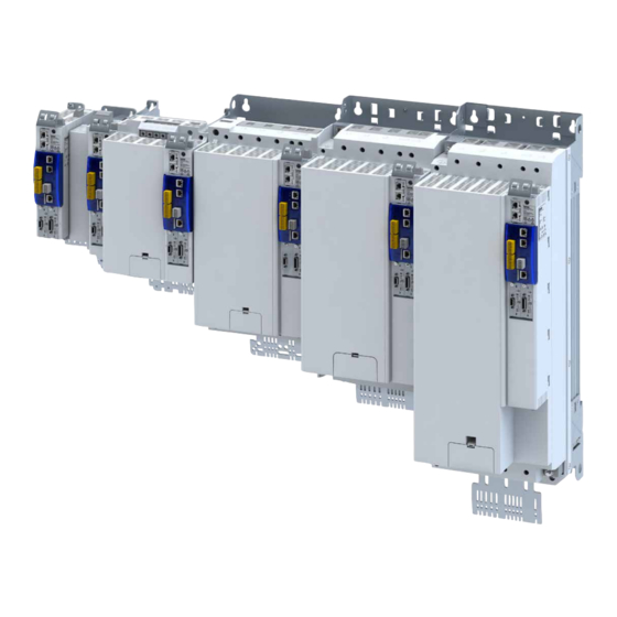
Lenze i950 Project Planning
Cabinet inverter
Hide thumbs
Also See for i950:
- Manual (500 pages) ,
- Commissioning manual (496 pages) ,
- Mounting and switch-on instructions (188 pages)
Table of Contents
Advertisement
Quick Links
Advertisement
Table of Contents

Related Manuals for Lenze i950


Summary of Contents for Lenze i950
- Page 1 Project planning | EN Inverter i950 cabinet inverter 0.55 ... 110 kW...
-
Page 3: Table Of Contents
Contents Contents About this document Document description Further documents Notations and conventions Product information Product description Identification of the products Features The modular system Topologies / network Technology applications (TA) Overview "CiA 402 Advanced" technology application "Electronic Gearbox" technology application "Speed Control"... - Page 4 Contents Information on electrical installation Important notes Preparation Connection according to UL Mains connection 3-phase mains connection 400 V 3-phase mains connection 480 V Motor connection Connection to the IT system Supply voltage connection Connection of motor temperature monitoring Motor holding brake connection Brake resistor connection DC-bus connection Control connections...
- Page 5 Contents Technical data Standards and operating conditions Conformities and approvals Protection of persons and device protection EMC data Motor connection Environmental conditions Electrical supply conditions Certification of the integrated safety 3-phase mains connection 400 V Rated data Fusing data Terminal data Brake resistors Mains chokes RFI filters / Mains filters...
- Page 6 Contents Product extensions Overview I/O extensions Data of control connections Further control connections PTC input Motor encoder connection Load encoder/master encoder connection Networks EtherCAT PROFINET EtherCAT system bus...
- Page 7 Contents Functional safety General information and basics Safety address Stop functions Prioritisation Restart Safety sensors Slip compensation Safety functions Safe torque off (STO) Safe stop emergency (SSE) Safe stop 1 (SS1) Safe stop 2 (SS2) Ramp monitoring Safe operating stop (SOS) Safe maximum speed (SMS) Safely-limited speed (SLS) Safe speed monitor (SSM)
- Page 8 Contents Accessories Overview Operation and diagnostics Setpoint potentiometer Memory modules Brake resistors Mains chokes RFI filters / Mains filters Power supply units Mounting Shield mounting kit Terminal strips DIN rail System cables Purchase order Notes on ordering Order code Appendix Declarations of Conformity Good to know Approvals and directives...
-
Page 9: About This Document
Download in different formats from the EASY Product Finder EPLAN macros Project planning, documentation and management of projects for EPLAN P8. These media can be found here: Lenze.com Information and tools with regard to the Lenze products can be found on the Internet: www.Lenze.com à Downloads... -
Page 10: Notations And Conventions
About this document Notations and conventions Notations and conventions This document uses the following conventions to distinguish different types of information: Numeric notation Decimal separator Point The decimal point is always used. Example: 1 234.56 Warning UL warning Are used in English and French. UR warning Text Engineering tools... -
Page 11: Product Information
Product information Product description Product information Product description The Servo Inverter i950 is an expansion for our automation platform and can easily be integrated into servo drive systems. The Servo Inverter provides a high-quality servo inverter. • Already today, the standard for efficiency classes (IE) in accordance with EN 50598-2, which will apply in the future, has been met. - Page 12 ^ 163 Information on the available technology applications: 4Technology applications (TA) ^ 22 The technology applications for the Servo Inverter i950 are selected and parameterized • with Easy Starter. The technology applications in inverters utilize procedures comparable to technology •...
- Page 13 • In this case, STO is the only usable safety function. i950 with extended safety • Numerous safety functions are available here. 4Functional safety ^ 109 i950 - variant with basic safety - STO i950 - variant with extended safety...
-
Page 14: Identification Of The Products
Type Rated power Rated line voltage No. of phases Inverter 0.55 i950-C0.55/400-3 0.75 i950-C0.75/400-3 i950-C2.2/400-3 i950-C4.0/400-3 i950-C7.5/400-3 i950-C11/400-3 i950-C15/400-3 i950 cabinet inverter i950-C22/400-3 i950-C30/400-3 i950-C45/400-3 i950-C55/400-3 i950-C75/400-3 i950-C90/400-3 i950-C110/400-3 Inverter series Type Rated power Rated line voltage No. of phases Inverter 0.55... -
Page 15: Features
Product information Features Features The following figures give an overview of the elements and connections on the devices. Position, size and appearance of elements and connections may vary depending on the capacity and size of the equipment. Some equipment may be optional. Power range 0.55 kW ... - Page 16 Product information Features Power range 7.5 kW ... 15 kW X100 Mains connection X101 DC bus Option PE connection Shielding of control connections 24 V supply Control electronics Network status LEDs X2x6 Network Option X2x7 Network X236 System bus EtherCAT IN Option Inverter status LEDs X237...
- Page 17 Product information Features Power range22 kW X100 Mains connection/DC bus PE connection Shielding of control connections 24 V supply Control electronics Network status LEDs X2x6 Network Option System bus EtherCAT X2x7 Network X236 Option X237 Inverter status LEDs Basic Safety - STO Control terminal SD card Option...
- Page 18 Product information Features Power range 30 kW ... 45 kW Shielding of control X100 Mains connection connections 24 V supply PE connection Control electronics X2x6 Network Network status LEDs Option X2x7 Network System bus EtherCAT Option X236 Inverter status LEDs X237 Basic Safety - STO SD card...
- Page 19 Product information Features Power range 55 kW ... 75 kW Shielding of X100 Mains connection/DC bus control connections PE connection IT screw 24 V supply X2x6 Network Control electronics Option Network status LEDs X2x7 Network Option System bus EtherCAT IN X236 Inverter status LEDs Basic Safety - STO...
- Page 20 Product information Features Power range 90 kW ... 110 kW Mains connection/DC bus X100 Shielding of control connections PE connection IT screw 24 V supply Control electronics X2x6 Network Option Network status LEDs X2x7 Network Option System bus EtherCAT IN X236 Inverter status LEDs X237...
-
Page 21: The Modular System
EtherCAT® is a registered trademark and patented technology, licensed by Beckhoff Automation GmbH, Germany. Device descriptions for the download: XML/ESI files for Lenze devices PROFINET® (Process Field Network) is a real-time capable fieldbus system based on Ethernet. -
Page 22: Technology Applications (Ta)
• Interface to the fieldbus and use of the safety functions via PROFIsafe or FSoE • This technology application enables the i950 to be optimally operated as a Cia device with control units of other manufacturers. "Electronic Gearbox" technology application... -
Page 23: Speed Control" Technology Application
Product information Technology applications (TA) "Speed Control" technology application "Speed Control" technology application For conveyor drives and traveling drives Operation at constant speed with high concentricity factor • High control performance with speed stability • Start-up and deceleration profiles • Process control/torque control •... -
Page 24: One Cable Technology (Oct) Via Hiperface Dsl
Product information One cable technology (OCT) via HIPERFACE DSL® One cable technology (OCT) via HIPERFACE DSL® With the aid of the open motor feedback protocol HIPERFACE DSL®, the i950 allows for the use of future-oriented One Cable Technology. Advantages The use of hybrid cables allows for combined servo and rotary transducer cables. -
Page 25: Information On Project Planning
Information on project planning Project planning process Operation in motor and generator mode Information on project planning Project planning process Operation in motor and generator mode The energy analysis differs between operation in motor mode and generator mode. During operation in motor mode, the energy flows from the supplying mains via the inverter to the motor which converts electrical energy into mechanical energy (e. -
Page 26: Overcurrent Operation
Information on project planning Project planning process Overcurrent operation Overcurrent operation The inverters can be driven at higher amperages beyond the rated current if the duration of this overcurrent operation is time limited. Two utilisation cycles of 15 s and 180 s are defined. Within these utilisation cycles, an overcurrent is possible for a certain time if afterwards an accordingly long recovery phase takes place. -
Page 27: Safety Instructions
The procedural notes and circuit details described are only proposals. It is up to the user to check whether they can be adapted to the particular applications. Lenze does not take any responsibility for the suitability of the procedures and circuit proposals described. -
Page 28: Handling
Information on project planning Safety instructions Handling Handling Transport, storage Observe the notes regarding transport, storage and correct handling. Ensure proper handling and avoid mechanical stress. Do not bend any components and do not change any insulation distances during transport or handling. Do not touch any electronic components and contacts. Inverters contain electrostatically sensitive components which can easily be damaged by inappropriate handling. - Page 29 Information on project planning Safety instructions Handling Disposal In accordance with the current provisions, Lenze products and accessories have to be disposed of by means of professional recycling. Lenze products contain contain recyclable raw material such as metal, plastics and electronic components.
-
Page 30: Residual Hazards
Information on project planning Safety instructions Residual hazards Residual hazards Even if notes given are taken into consideration and protective measures are implemented, the occurrence of residual risks cannot be fully prevented. The user must take the residual hazards mentioned into consideration in the risk assessment for his/her machine/system. - Page 31 Information on project planning Safety instructions Residual hazards Motor If there is a short circuit of two power transistors, a residual movement of up to 180°/number of pole pairs can occur at the motor! (e. g. 4-pole motor: residual movement max. 180°/2 = 90°).
-
Page 32: Control Cabinet Structure
Information on project planning Control cabinet structure Arrangement of components Control cabinet structure Control cabinet requirements Protection against electromagnetic interferences • Compliance with the ambient conditions of the installed components • Mounting plate requirements The mounting plate must be electrically conductive. •... -
Page 33: Cables
Information on project planning Control cabinet structure Cables Cables Requirements The cables used must correspond to the requirements at the location (e. g. EN 60204−1, • UL). The cable cross-section must be dimensioned for the assigned fusing. Observe national • and regional regulations. -
Page 34: Emc-Compliant Installation
• separately from the motor cable. In Lenze system cables, the cable for brake control is integrated into the motor cable. If this cable is not required for brake control, it can also be used to connect the motor temperature monitoring up to a length of 50 m. - Page 35 Information on project planning Control cabinet structure EMC-compliant installation Detecting and eliminating EMC interferences Trouble Cause Remedy Interferences of analog setpoints of your own Unshielded motor cable has been used Use shielded motor cable or other devices and measuring systems Shield contact is not extensive enough Carry out optimal shielding as specified Shield of the motor cable is interrupted, e.
-
Page 36: Information On Mechanical Installation
Information on mechanical installation Important notes Information on mechanical installation Important notes Measures for cooling during operation Ensure unimpeded ventilation of cooling air and outlet of exhaust air. • If the cooling air is polluted (fluff, (conductive) dust, soot, grease, aggressive gases), take •... -
Page 37: Preparation
Information on mechanical installation Preparation Preparation Further data and information for mechanical mounting: 4Control cabinet structure ^ 32 4Dimensions ^ 86 The scope of supply of the inverter comprises mounting instructions. They describe technical data and information on mechanical and electrical installation. -
Page 38: Functional Safety
The functions dependent on speed and/or direction of rotation are performed with errors. ▶ Reliably exclude functional errors via design measures. ▶ Utilize motors and encoder systems with guaranteed characteristics. Your Lenze contact will be glad to provide you with a list of suitable systems. - Page 39 Information on mechanical installation Functional safety 2-encoder concept Safe speed monitoring can always be achieved with a 2-encoder concept. A 2-encoder concept is a machine combination which usually utilizes the following components: Motor encoder: Resolver • Position/load encoder: absolute value encoder (Sin-Cos), incremental encoder (TTL), or •...
-
Page 40: Information On Electrical Installation
Information on electrical installation Important notes Information on electrical installation Important notes DANGER! Danger to life due to electric shock! Death or serious injury ▶ Any work on the inverter must only be carried out in the deenergized state. ▶ Inverter up to 45 kW: After switching off the mains voltage, wait for at least 5 min before you start working. - Page 41 Possible consequences: The filters may be destroyed when an earth fault occurs. Possible consequences: Monitoring of the IT system may be triggered. ▶ Do not use mains filters and RFI filters from Lenze in IT systems. ▶ Before using the inverter in the IT system, remove the IT screws.
-
Page 42: Preparation
Information on electrical installation Preparation NOTICE Overvoltage at components In case of an earth fault in IT systems, intolerable overvoltages may occur in the plant. Possible consequences: Destruction of the device. ▶ Before using the inverter in the IT system, the contact screws must be removed. ▶... -
Page 43: Connection According To Ul
Information on electrical installation Connection according to UL Connection according to UL WARNING! ▶ UL/CSA marking ▶ Secondary circuit shall be supplied from an external isolating source. ▶ Maximum surrounding air temperature is 45 °C. ▶ Maximum surrounding air temperature with derating is 55 °C. ▶... - Page 44 Information on electrical installation Connection according to UL WARNING! ▶ UL marking ▶ Use 75°C copper wire only, except for control circuits. ▶ Marquage UL ▶ Utiliser exclusivement des conducteurs en cuivre 75 °C, sauf pour la partie commande. WARNING! ▶...
- Page 45 Information on electrical installation Connection according to UL Inverter Alternate Fuse (Semiconductor Fuse) Line voltage Rated power Rated power SCCR Max. rated current 480 V, 3-ph 0.55 0.75 480 V, 3-ph 0.75 480 V, 3-ph 480 V, 3-ph 480 V, 3-ph 480 V, 3-ph 480 V, 3-ph 480 V, 3-ph...
-
Page 46: Mains Connection
Information on electrical installation Mains connection Mains connection The following should be considered for the mains connection of inverters: Single inverters are either directly connected to the AC system or via upstream filters. RFI filters are already integrated in many inverters. Depending on the requirements, mains chokes or mains filters can be used. -
Page 47: 3-Phase Mains Connection 400 V
3-phase mains connection 400 V 3-phase mains connection 400 V A mains choke is required for the operation of inverters ≥ 15 KW. The connection plan is valid for the inverters i950-Cxxx/400-3. 3/N/PE AC 400 V 3/PE AC 340 V ... 528 V 45 Hz ... -
Page 48: 3-Phase Mains Connection 480 V
3-phase mains connection 480 V 3-phase mains connection 480 V A mains choke is required for the operation of inverters ≥ 15 KW. The connection plan is valid for the inverters i950-Cxxx/400-3. 3/N/PE AC 480 V 3/PE AC 340 V ... 528 V 45 Hz ... -
Page 49: Motor Connection
Information on electrical installation Motor connection Motor connection Switching in the motor cable Switching on the motor side of the inverter is permissible: For safety shutdown (emergency stop). In case several motors are driven by one inverter (only in V/f operating mode). Please note the following: The switching elements on the motor side must be dimensioned for with the maximum occurring load. -
Page 50: Connection To The It System
Information on electrical installation Connection to the IT system Connection to the IT system NOTICE Internal components have earth/ground potential if the IT screws are not removed. The monitoring devices of the IT system will be triggered. ▶ Before connection to an IT system be absolutely sure to remove the IT screws. I95AE155F, I95AE175F, I95AE222F, I95AE240F I95AE275F, I95AE311F, I95AE315F TX10... - Page 51 Information on electrical installation Connection to the IT system I95AE322F...
- Page 52 Information on electrical installation Connection to the IT system I95AE330F, I95AE345F I95AE355F, I95AE375F...
-
Page 53: Supply Voltage Connection
Information on electrical installation Supply voltage connection I95AE390F, I95AE411F Supply voltage connection An external 24 V supply voltage to X5:24E/GE is necessary for supplying the control electronics. If the control electronics are supplied independently of the AC grid of the inverter, the inverter can also be configured when the AC grid is turned off. -
Page 54: Connection Of Motor Temperature Monitoring
Information on electrical installation Connection of motor temperature monitoring Connection of motor temperature monitoring If the terminal X109 is used, e. g. for connecting an external PTC thermistor or a thermal contact, ensure at least one basic insulation to the potentials of motor, mains and control terminals to not restrict the safe isolation of the control terminals. -
Page 55: Motor Holding Brake Connection
Information on electrical installation Motor holding brake connection Motor holding brake connection The inverter is designed for 24 V brakes. A motor holding brake is connected to X106 and supplied via X107. DANGER! A common power supply unit for X107 and X5 removes the safe isolation of the control card from the mains potential - even if a SELV/PELV power supply unit is used. - Page 56 Information on electrical installation Motor holding brake connection 24 V supply of motor holding brake Terminal X107: 24B, GB DC supply of X106 Specification of external power SELV/PELV supply unit Rated input voltage +24 ± 20 % Max. input current 0.55 ...
-
Page 57: Brake Resistor Connection
Information on electrical installation Brake resistor connection Brake resistor connection Short connecting cables up to 0.5 m Up to a cable length of 0.5 m, the cable for the brake resistor and that of the temperature monitoring can be twisted. Doing so reduces problems due to EMC interference. RB1 RB2 T1 T2 ①... -
Page 58: Dc-Bus Connection
Information on electrical installation DC-bus connection DC-bus connection If multiple drives are operated in a group, energy exchange between individual drives working as motors and generators is possible. To do so, inverter groups are connected to the DC link. For this purpose, the inverters have to be provided with a connection for the DC link, e.g. -
Page 59: Connection Of One Cable Technology (Oct) Via Hiperface Dsl
Connection of one cable technology (OCT) via HIPERFACE DSL® Connection of one cable technology (OCT) via HIPERFACE DSL® Conditions The One Cable Technology (OCT) is possible with Lenze MCS and m850 servo motors. • The motor must be equipped with a HIPERFACE DSL® encoder. -
Page 60: Networks
Information on electrical installation Networks EtherCAT Networks EtherCAT Typical topologies Line Master Slave Device Bus-related information Name EtherCAT Communication medium Ethernet 100 Mbps, full duplex Connected as EtherCAT slave Status display 2 LEDs (RUN, ERR) PROFINET Typical topologies Line Tree Ring IO controller Switch SCALANCE (MRP capable) -
Page 61: Ethercat System Bus
Information on electrical installation Networks EtherCAT system bus EtherCAT system bus Typical topologies Line SD15 Master device Slave Device Bus-related information Name EtherCAT system bus Communication medium Ethernet 100 Mbps, full duplex Connection of the inverter to the system bus cross communication or as standard EtherCAT slave Status display 1 LED (RUN) -
Page 62: Functional Safety
Information on electrical installation Functional safety Functional safety DANGER! Improper installation of the safety engineering system can cause an uncontrolled starting action of the drives. Possible consequence: Death or severe injuries ▶ Safety engineering systems may only be installed and commissioned by qualified personnel. ▶... -
Page 63: Basic Safety - Sto
Information on electrical installation Functional safety Basic Safety - STO Basic Safety - STO Basic Safety - STO is part of the product version i95AExxxF1A. DANGER! With the "Safe torque off" (STO) function, no “emergency‑stop" can be executed according to EN 60204−1 without additional measures. -
Page 64: Connection Diagram
Information on electrical installation Functional safety Basic Safety - STO Connection diagram Active sensors Active sensor - example of lightgrid Passive sensors +24 V DC 24 V SELV/PELV Passive sensor Passive sensor Safety switching device Passive sensors - further examples Emergency stop (STO) SS1c/SS1-t Emergency stop (SS1c/SS1-t) -
Page 65: Terminal Data
Information on electrical installation Functional safety Basic Safety - STO Terminal data Specification Unit min. typ. max. SIA, SIB LOW signal HIGH signal Running time Clear time Input current Input peak current Input capacitance SIA µF Input capacitance SIB Test pulse duration Test pulse interval Reference potential for SIA and SIB Runtime = Start of rising edge at SIA, SIB until internal HIGH signal is detected. -
Page 66: Extended Safety
Information on electrical installation Functional safety Extended Safety Extended Safety Extended safety is part of the product version i950AExxxF1A. DANGER! Loss of the safety function. A loss of the safety function causes an unsafe condition of the machine. The machine condition cannot be controlled via the safety function. -
Page 67: Connection Diagram
Information on electrical installation Functional safety Extended Safety Connection diagram ① ② 24 V ext. ③ SHOM ④ ⑤ SHOM ⑥ Fig. 9: Sample circuit Name Meaning Passive sensor with channel A and B Protected laying for category 4 according to EN ISO 13849-2 necessary Active sensor: upstream safety control Active sensor: light curtain ①... -
Page 68: Terminal Data
Information on electrical installation Functional safety Extended Safety Terminal data Specification Unit min. typ. max. CLA, CLB PLC output, IEC-61131-2, 24 V DC, 50 mA Low signal output voltage +0,8 High signal output voltage Output current Cable capacity Cable resistance of a passive sensor Ω... -
Page 69: Technical Data
Technical data Standards and operating conditions Conformities and approvals Technical data Standards and operating conditions Conformities and approvals Conformity 2006/42/EC Machinery Directive 2014/30/EU EMC Directive (reference: CE-typical drive system) TR CU 004/2011 Eurasian conformity: Safety of low voltage equipment Eurasian conformity: Electromagnetic compatibility of technical TR CU 020/2011 means Restrictions on the use of certain hazardous substances in... -
Page 70: Motor Connection
Technical data Standards and operating conditions Motor connection Motor connection Requirements for the shielded motor cable Capacitance per unit length C-core-core/C-core-shielding < 75/150 pF/m ≤ 2.5 mm² / AWG 14 C-core-core/C-core-shielding < 150/300 pF/m ≥ 4 mm² / AWG 12 Electric strength Uo = r.m.s. -
Page 71: Certification Of The Integrated Safety
EN 61800−5−2: Adjustable speed electrical power drive systems − Part 5−2: Safety • requirements − functional safety EN 62061: Safety of machinery − functional safety of safety-related electrical/electronic/ • programmable electronic systems Declarations of Conformity and certificates can be found on the internet at http://www.Lenze.com... -
Page 72: 3-Phase Mains Connection 400 V
Technical data 3-phase mains connection 400 V Rated data 3-phase mains connection 400 V Rated data Inverter i950-C0.55/400-3 i950-C0.75/400-3 i950-C2.2/400-3 i950-C4.0/400-3 Rated power 0.55 0.75 Rated power 0.75 Line voltage range 3/PE AC 340 V ... 528 V, 45 Hz ... 65 Hz... - Page 73 Technical data 3-phase mains connection 400 V Rated data Inverter i950-C7.5/400-3 i950-C11/400-3 i950-C15/400-3 i950-C22/400-3 Rated power Rated power Line voltage range 3/PE AC 340 V ... 528 V, 45 Hz ... 65 Hz Output voltage 3 AC 0-400 V Rated line current Without choke 28.4...
- Page 74 Technical data 3-phase mains connection 400 V Rated data Inverter i950-C30/400-3 i950-C45/400-3 i950-C55/400-3 i950-C75/400-3 Rated power Rated power Line voltage range 3/PE AC 340 V ... 528 V, 45 Hz ... 65 Hz Output voltage 3 AC 0-400 V Rated line current...
- Page 75 Technical data 3-phase mains connection 400 V Rated data Inverter i950-C90/400-3 i950-C110/400-3 Rated power Rated power Line voltage range 3/PE AC 340 V ... 528 V, 45 Hz ... 65 Hz Output voltage 3 AC 0-400 V Rated line current...
-
Page 76: Fusing Data
Circuit breaker Earth-leakage circuit breaker Characteristic Max. rated Characteristic Max. rated current current i950-C0.55/400-3 gG/gL or gRL ≥ 30 mA, type B i950-C0.75/400-3 gG/gL or gRL ≥ 30 mA, type B i950-C2.2/400-3 gG/gL or gRL ≥ 30 mA, type B i950-C4.0/400-3... -
Page 77: Brake Resistors
Brake resistor Order code Rated resistance Rated power Thermal capacity Dimensions (h x w Weight x d) Ω i950-C0.55/400-3 ERBM390R100W 235 x 21 x 40 0.37 i950-C0.75/400-3 ERBP180R300W 320 x 41 x 122 i950-C2.2/400-3 ERBP180R200W 240 x 41 x 122... -
Page 78: Rfi Filters / Mains Filters
Reduced leakage current, operation with 30 mA residual current circuit breaker is possible • Inverter Filters Order code rated current Dimensions (h x w x d) Weight i950-C0.55/400-3 I0FAE175F100S0000S 276 x 60 x 50 i950-C0.75/400-3 i950-C2.2/400-3 I0FAE222F100S0000S 346 x 60 x 50 i950-C7.5/400-3... -
Page 79: 3-Phase Mains Connection 480 V
Technical data 3-phase mains connection 480 V Rated data 3-phase mains connection 480 V Rated data Inverter i950-C0.55/400-3 i950-C0.75/400-3 i950-C2.2/400-3 i950-C4.0/400-3 Rated power 0.55 0.75 Rated power 0.75 Line voltage range 3/PE AC 340 V ... 528 V, 45 Hz ... 65 Hz... - Page 80 Technical data 3-phase mains connection 480 V Rated data Inverter i950-C7.5/400-3 i950-C11/400-3 i950-C15/400-3 i950-C22/400-3 Rated power Rated power Line voltage range 3/PE AC 340 V ... 528 V, 45 Hz ... 65 Hz Output voltage 3 AC 0-480 V Rated line current Without choke 16.6...
- Page 81 Technical data 3-phase mains connection 480 V Rated data Inverter i950-C30/400-3 i950-C45/400-3 i950-C55/400-3 i950-C75/400-3 Rated power Rated power Line voltage range 3/PE AC 340 V ... 528 V, 45 Hz ... 65 Hz Output voltage 3 AC 0-480 V Rated line current...
- Page 82 Technical data 3-phase mains connection 480 V Rated data Inverter i950-C90/400-3 i950-C110/400-3 Rated power Rated power Line voltage range 3/PE AC 340 V ... 528 V, 45 Hz ... 65 Hz Output voltage 3 AC 0-480 V Rated line current...
-
Page 83: Fusing Data
Circuit breaker Earth-leakage circuit breaker Characteristic Max. rated Characteristic Max. rated current current i950-C0.55/400-3 gG/gL or gRL ≥ 30 mA, type B i950-C0.75/400-3 gG/gL or gRL ≥ 30 mA, type B i950-C2.2/400-3 gG/gL or gRL ≥ 30 mA, type B i950-C4.0/400-3... -
Page 84: Brake Resistors
Brake resistor Order code Rated resistance Rated power Thermal capacity Dimensions (h x w Weight x d) Ω i950-C0.55/400-3 ERBM390R100W 235 x 21 x 40 0.37 i950-C0.75/400-3 ERBP180R300W 320 x 41 x 122 i950-C2.2/400-3 ERBP180R200W 240 x 41 x 122... -
Page 85: Rfi Filters / Mains Filters
Reduced leakage current, operation with 30 mA residual current circuit breaker is possible • Inverter Filters Order code rated current Dimensions (h x w x d) Weight i950-C0.55/400-3 I0FAE175F100S0000S 276 x 60 x 50 i950-C0.75/400-3 i950-C2.2/400-3 I0FAE222F100S0000S 346 x 60 x 50 i950-C7.5/400-3... -
Page 86: Dimensions
The specified installation clearances are minimum dimensions to ensure a sufficient air circulation for cooling purposes. They do not consider the bend radiuses of the connecting cables. 0.55 kW ... 4 kW The dimensions in mm apply to: 0.55 kW i950-C0.55/400-3 0.75 kW i950-C0.75/400-3 2.2 kW i950-C2.2/400-3 4 kW... - Page 87 Technical data Dimensions 0.75 hp ... 5.5 hp The dimensions in inch apply to: 0.75 hp i950-C0.55/400-3 1 hp i950-C0.75/400-3 3 hp i950-C2.2/400-3 5.5 hp i950-C4.0/400-3...
- Page 88 Technical data Dimensions 7.5 kW ... 15 kW The dimensions in mm apply to: 7.5 kW i950-C7.5/400-3 11 kW i950-C11/400-3 15 kW i950-C15/400-3...
- Page 89 Technical data Dimensions 10 hp ... 20 hp The dimensions in inch apply to: 10 hp i950-C7.5/400-3 15 hp i950-C11/400-3 20 hp i950-C15/400-3...
- Page 90 Technical data Dimensions 22 kW The dimensions in mm apply to: 22 kW i950-C22/400-3...
- Page 91 Technical data Dimensions 30 hp The dimensions in inch apply to: 30 hp i950-C22/400-3...
- Page 92 Technical data Dimensions 30 kW ... 45 kW The dimensions in mm apply to: 30 kW i950-C30/400-3 45 kW i950-C45/400-3...
- Page 93 Technical data Dimensions 40 hp ... 60 hp The dimensions in inch apply to: 40 hp i950-C30/400-3 60 hp i950-C45/400-3...
- Page 94 Technical data Dimensions 55 kW ... 75 kW The dimensions in mm apply to: 55 kW i950-C55/400-3 75 kW i950-C75/400-3...
- Page 95 Technical data Dimensions 75 hp ... 100 hp The dimensions in inch apply to: 75 hp i950-C55/400-3 100 hp i950-C75/400-3...
- Page 96 Technical data Dimensions 90 kW ... 110 kW The dimensions in mm apply to: 90 kW i950-C90/400-3 110 kW i950-C110/400-3...
- Page 97 Technical data Dimensions 120 hp ... 150 hp The dimensions in inch apply to: 120 hp i950-C90/400-3 150 hp i950-C110/400-3...
-
Page 98: Product Extensions
Product extensions Overview Product extensions Overview Product expansions allow you to flexibly tailor the inverter to your application. 4Motor encoder connection ^ 102 4Load encoder/master encoder connection ^ 104 4Networks ^ 105 4Functional safety ^ 109... -
Page 99: I/O Extensions
Product extensions I/O extensions Data of control connections I/O extensions Data of control connections Digital inputs X3: DI1, DI2, DI3, DI4 / GI Switching type Parameterizable Use case 1 Standard digital input Use case 2 Touch probe input Maximum of 8 markers per ms detectable with a temporal resolution of 10 ns. - Page 100 Product extensions I/O extensions Data of control connections Analog inputs X3: AI1+ / AI1- Sampling frequency Resolution of A/D converter Operation as voltage input Connection designation X3/AI1+, X3/AI1- Input voltage DC 0 … 10 Input resistance kΩ > 100 Accuracy ±...
-
Page 101: Further Control Connections
Further control connections PTC input In the Lenze setting, motor temperature monitoring is activated! There is a wire jumper between the terminals T1 and T2 by default. Before connecting a thermal sensor, remove the wire jumper. In case of inverters up to and including i950-C15/400-3, the PTC evaluation can only be applied if the One Cable Technology (OCT) is used. -
Page 102: Motor Encoder Connection
Product extensions Motor encoder connection Motor encoder connection The i950 can optionally be outfitted with a module for motor feedback (motor encoder). Two modules are available: Resolver module • Multi encoder module • Resolver module Resolvers are connected to X7 (9-pole Sub-D socket). - Page 103 Product extensions Motor encoder connection Pin assignment of resolver connection Connection Connection Connection type Resolver description +REF - REF n.c. +COS Resolver Sub-D, 9-pole -COS +SIN -SIN TEMP+ TEMP- Pin assignment of multi encoder connection Connection Connection Connection type Encoder type description SinCos Hiperface...
-
Page 104: Load Encoder/Master Encoder Connection
Load encoder/master encoder connection Load encoder/master encoder connection The i950 can optionally be outfitted with a module for application feedback (load encoder or master encoder). The modules used for the load encoder/master encoder and the motor encoder are the same. -
Page 105: Networks
Product extensions Networks Networks The i950 can optionally be outfitted with a network module. It is used to realize communication at the "fieldbus" level. Modules are available for connecting the following: EtherCAT® • PROFINET® • For configuration and diagnosis via software, the i950 is equipped with the following: Engineering-Port (Ethernet) •... -
Page 106: Ethercat
Product extensions Networks EtherCAT EtherCAT EtherCAT® (Ethernet for Controller and Automation Technology) is an Ethernet-based fieldbus system which fulfils the application profile for industrial plant systems. The EtherCAT communication module Typical topologies Line SD15 Master device Slave Device Connection description EtherCAT Connection X246... -
Page 107: Profinet
Product extensions Networks PROFINET Modules for network Network (fieldbus) Order code EtherCAT I9MAFT0000000S PROFINET PROFINET is a common fieldbus for the connection of inverters to different control systems in plants. PROFINET communication module Connection description PROFINET Connection X256 X257 Connection type RJ45 Technical data Communication profile... -
Page 108: Ethercat System Bus
EtherCAT system bus EtherCAT system bus The EtherCAT system bus is the standard “on-board” bus system of the i950. Thanks to the integrated synchronization mechanism, the "Distributed clocks" and the short cycle times, it offers excellent real-time properties. Thus it enables a high-precision synchronization of the connected nodes. -
Page 109: Functional Safety
Product extensions Functional safety General information and basics Functional safety General information and basics The functional safety describes the necessary measures that need to be taken by means of electrical or electronic equipment to prevent or eliminate dangers due to malfunctions. Protective devices prevent any human access to danger areas during normal operation. -
Page 110: Prioritisation
Product extensions Functional safety General information and basics Prioritisation Stop functions with higher priority influence the flow of lower-order functions which have already been initiated. Hierarchy: Safe torque off (STO) The function STO has the highest priority and hence precedence over all other functions. -
Page 111: Safety Sensors
Product extensions Functional safety Safety sensors Safety sensors Kontaktfunktionstest An internal contact function test is carried out at the safe inputs. Safe input in the ON state A LOW level at one channel puts the input in the OFF state. The discrepancy monitoring •... - Page 112 Product extensions Functional safety Safety sensors Connection of active sensors The safe sensor inputs X83 / I1A ... I4B are suitable for active sensors. P/M-switched input signals are permissible. The circuit monitoring must correspond to the requirements of category 3 or category 4. No circuit monitoring takes place via the integrated safety equipment.
-
Page 113: Slip Compensation
Product extensions Functional safety Slip compensation Slip compensation When an operational slip occurs between the load and motor encoders, the slip is evaluated and compensated for via the function. WARNING! The slip compensation may not be suitable for the application. Serious injuries when exceeding the travel path. - Page 114 Product extensions Functional safety Slip compensation Activating slip compensation In order to activate slip compensation, the diagnostics markers are required. The ① ② diagnostics markers provide a cyclic indication of the accuracy of the position encoder. In order for a sufficient braking distance to be available in the case of a fault, the diagnostic markers must be arranged such that a fault in the range of the maximum permissible speed is recognised.
-
Page 115: Safety Functions
Product extensions Functional safety Safety functions Safety functions Supported safety functions for "Basic Safety-STO" 4Safe torque off (STO) ^ 116 Supported safety functions for "Extended Safety" 4Safe torque off (STO) ^ 116 4Safe stop emergency (SSE) ^ 118 4Safe stop 1 (SS1) ^ 119 4Safe stop 2 (SS2) ^ 121... -
Page 116: Safe Torque Off (Sto)
Product extensions Functional safety Safety functions Safe torque off (STO) The motor cannot generate torque and movements of the drive. DANGER! With the "Safe torque off" (STO) function, no “emergency‑stop" can be executed according to EN 60204−1 without additional measures. There is no electrical isolation between the motor and inverter and no service switch or maintenance switch! Possible consequences: Death or severe injuries ▶... - Page 117 Product extensions Functional safety Safety functions µC Fig. 12: Functional principle: Basic Safety - STO Control terminals of the safety unit PWM Pulse width modulation Hardware interface Motor µC Microcontroller Functional description Fig. 13: Safety function STO Functional sequence and error response have no adjustable parameters. Activation of the function A data telegram is sent to the inverter via the safety bus.
-
Page 118: Safe Stop Emergency (Sse)
Product extensions Functional safety Safety functions Safe stop emergency (SSE) The safety function SSE has the highest priority. The safety function SSE is controlled primarily from all states, operating modes or safety functions. Depending on the parameter setting in 0x28A3:001, SSE activates one of these functions: 4Safe torque off (STO) 4Safe stop 1 (SS1) Exception... -
Page 119: Safe Stop 1 (Ss1)
Product extensions Functional safety Safety functions Safe stop 1 (SS1) The safety function monitors the parameterized stopping time of the drive (n = 0). In the SS1 function, the drive switches to torqueless state via the parameterized mode. 0x2897:001 Preconditions The drive is brought to standstill via the application. - Page 120 Product extensions Functional safety Safety functions Via a safe input, if the corresponding parameter is assigned to the safe input. In response to the error stop request. In response to the emergency stop request. Parameter Extended-Safety Parameter Source Information 0x2890 STO: SD-In Function source of the safe inputs for requesting the STO function...
-
Page 121: Safe Stop 2 (Ss2)
Product extensions Functional safety Safety functions Safe stop 2 (SS2) The safety function monitors whether the drive has reached the set tolerance window (n = 0) within the parameterised stopping time. After the stopping time has elapsed or the value has fallen below the tolerance window, the monitoring function switches to safe operational stop (SOS) or activates the safety function (STO). - Page 122 Product extensions Functional safety Safety functions Response of the function in the event of an error An error message and an error stop are triggered if: Standstill could not be reached when the stopping time has elapsed (0x2894:001. • The activated ramp monitoring exceeds the parameterized deceleration ramp. •...
-
Page 123: Ramp Monitoring
The following parameter determines whether the relative or the absolute offset value is to be used. 0x2894:004 In the Lenze setting of the start offset, the tolerance window (n=0) is considered as the offset.0x2894:005 The monitoring ramp starts after an internal deceleration time has elapsed. The internal deceleration time depends on “SS1, SS2”: smoothing time”... - Page 124 Product extensions Functional safety Safety functions Activation If the stop functions SS1/SS2 are requested, a monitoring ramp is calculated and placed • over the current speed characteristic. Normal behaviour While the stopping time elapses or before the tolerance window (n = 0) is reached, the parameterised speed ramp is not exceeded.
-
Page 125: Safe Operating Stop (Sos)
Product extensions Functional safety Safety functions Safe operating stop (SOS) In the safe operational stop, the drive is not switched to torque-free operation. All control functions are maintained. The reached position remains active. WARNING! A safety-rated encoder system must be used. Without an encoder, this safety function cannot be used. -
Page 126: Safe Maximum Speed (Sms)
Product extensions Functional safety Safety functions Safe maximum speed (SMS) The safety function monitors the compliance with the safe maximum motor speed set. WARNING! A safety-rated encoder system must be used. Without an encoder, this safety function cannot be used. ▶... -
Page 127: Safely-Limited Speed (Sls)
Product extensions Functional safety Safety functions Safely-limited speed (SLS) The safety function monitors the parameterized speed Nlim if the following states are reached: The values have fallen below the parameterized speed. • The set braking time has elapsed. • WARNING! A safety-rated encoder system must be used. -
Page 128: Safe Speed Monitor (Ssm)
Product extensions Functional safety Safety functions Safe speed monitor (SSM) The function monitors the limited speed set. The function is activated if: the monitoring limits are parameterised, or • the values are non-zero. • WARNING! A safety-rated encoder system must be used. Without an encoder, this safety function cannot be used. -
Page 129: Safely-Limited Increment (Sli)
Product extensions Functional safety Safety functions Safely-limited increment (SLI) With this function, a maximum permissible position change [incr] can be set. Within the position window, the increments parameterised can be traversed in positive and negative directions. There is no time limit for executing this function. If the increment limits parameterised are exceeded, an error stop is initiated. - Page 130 Product extensions Functional safety Safety functions Behaviour of the function in the event of an error If the maximum permissible position change is exceeded, an error stop is initiated. The following functions can be set as safe stop: 4Safe torque off (STO) ^ 116 4Safe stop 1 (SS1) ^ 119...
-
Page 131: Safe Direction (Sdi)
Product extensions Functional safety Safety functions Safe direction (SDI) The function monitors the direction of rotation of the motor. A parameterisable tolerance threshold ensures that the drive does not change the permissible direction of rotation. Within the limits parameterised, the drive can rotate in the impermissible direction of rotation. NOTICE The delay in 0x28BA:002... -
Page 132: Safely-Limited Position (Slp)
Product extensions Functional safety Safety functions If the tolerance threshold for the SDIpos or SDIneg direction set (0x28BA:003) is exceeded after the delay time has elapsed (0x28BA:002), an error message is triggered and the stop function set in 0x28BA:S004 is activated. Safely-limited position (SLP) The function monitors the lower and upper position limit. -
Page 133: Position-Dependent Safe Speed (Pdss)
Product extensions Functional safety Safety functions Position-dependent safe speed (PDSS) The function monitors the speed of a drive as a function of of the absolute position along a motion • range. allows for the utilisation of a physically limited motion range without the use of •... - Page 134 Product extensions Functional safety Safety functions Error behaviour If the envelope curve is exceeded or when the absolute position limits are exited, an error message is triggered and an error stop with the function set in the 0x28DE:011 parameter is initiated.
-
Page 135: Safe Homing (Shom)
Product extensions Functional safety Safety functions Safe homing (SHOM) This function supplements the position evaluation of the encoder systems used. See Information on mechanical installation. ^ 36 WARNING! In the switched-off state, the motor position must not be changed by external forces. A change in the motor position causes injuries and may even result in death. - Page 136 Product extensions Functional safety Safety functions Functional description The start of the homing process does not cause the drive to execute a homing process. The initialisation and motion control are both executed autonomously by the drive. Referenzieren abgeschlossen SHOM start 0x2880:001 0x2880:001 Timeout...
-
Page 137: Mini-Homing
Product extensions Functional safety Safety functions The home position parameterised is the absolute reference point for these safety functions: Safely-limited position (SLP) • ^ 132 Position-dependent safe speed (PDSS) • ^ 133 Safe cam (SCA) • ^ 138 The following states are shown: The "SHOM active"... -
Page 138: Safe Cam (Sca)
Product extensions Functional safety Safety functions Safe cam (SCA) The function monitors the lower and upper position limit. Preconditions The following function must be executed: Set upper position value. • Set lower position value. • Safe homing (SHOM) • Functional description In connection with this function, please also observe the information with regard to safe homing in chapter Safe homing... -
Page 139: Operation Mode Selector (Oms)
Product extensions Functional safety Safety functions Operation mode selector (OMS) This function serves to switch between normal operation and special operation of the drive. If the OMS safety function is requested via a HIGH signal, the safety function is switched off in the case of an open circuit. In this case, there exists no safety function in the case of an open circuit. - Page 140 Product extensions Functional safety Safety functions Activation of special operation By means of the "Operation mode selector" function, special operation is activated by an "ON state" on a safe input. The function Enable switch (ES) must have been assigned to the corresponding input by parameterisation.
-
Page 141: Enable Switch (Es)
Product extensions Functional safety Safety functions Enable switch (ES) This function makes it possible to override the normal stop functions Safe torque off (STO), • Safe stop 1 (SS1) • Safe stop 2 (SS2) • in special operation. Preconditions A safe input or the safety bus can be used for connecting an enable switch. If the safe input is used, the ES bit of the safety bus must be deactivated. -
Page 142: Repair Mode Selector (Rms)
Product extensions Functional safety Safety functions Repair mode selector (RMS) This function moves the drive from a situation that is blocking it ("Deadlock"). In the safety concept, this state is taken into consideration as a special case for actuating an axis connected. - Page 143 Product extensions Functional safety Safety functions Request of the repair mode The repair mode is requested by the "ON state" on a safe input. The function must have been assigned to the corresponding input by parameterisation. Only if no safe input is utilised, the function can be activated via the safety bus. Via the safety bus, a data telegram with a corresponding content is sent to the inverter, see safety bus .
-
Page 144: Sto Cascading (Cas)
(OMS). The STO stop function will trigger the "Cascading" function. Activation by means of the enable switch (ES) is not possible. Description of the principle i950 #1 i950 #2 i950 #n SD-Out1... -
Page 145: Safe Brake Control (Sbc)
Product extensions Functional safety Safety functions Safe brake control (SBC) (From standard device firmware V1.3, safety firmware V1.1 with parameter set version V1.1) The SBC function provides for a safe brake control by the inverter. The internal test rate of the brake output (X106) restricts the request rate to max. - Page 146 Product extensions Functional safety Safety functions Activation of the function A data telegram is sent to the inverter via the safety bus. See chapter "Safe network interfaces". ^ 148 Via a safe input, if the corresponding parameter is assigned to the safe input. Response of the function in the event of an error If an error is detected, the control of the brake is switched off.
-
Page 147: Safe Muting (Mut)
The safe muting function deactivates selected safe inputs and all functions of the safety bus. The safe muting function can only be activated via the LSPE (Lenze Safety Parameter Editor). For this purpose, a special muting password must be entered. -
Page 148: Safe Network Interfaces
PROFIsafe connection Inverter Safety bus: configuration 0x2128:000 PROFINET i950 PROFIsafe/PROFINET Operation with PROFIsafe via PROFINET is only permitted according to the specification PROFIsafe Profile for Safety Technology Version 2.x! Addressing In order to ensure that a data telegram reaches the right node, a unique PROFIsafe destination address is necessary. - Page 149 Product extensions Functional safety Safe network interfaces PROFIsafe output data The PROFIsafe output data (control data) is transmitted from the control. The value of a bit in the table indicates the active bit state: 0 = the function is LOW-active. •...
- Page 150 Product extensions Functional safety Safe network interfaces PROFIsafe input data The PROFIsafe input data (status information) is transmitted to the control. The value of a bit in the table indicates the active bit state: Name Value Information STO active The STO function is active and the drive is safely switched to torqueless operation. •...
- Page 151 Product extensions Functional safety Safe network interfaces Name Value Information RMS active Repair mode select is activated. Repair mode select is deactivated. OMS active The OMS function is active. Special operation • In contrast to bit 11 (OMS), this bit remains set until the special operation is canceled and the change-over to normal operation has taken place via the stop function.
-
Page 152: Fsoe Connection
Safety inputs: 31 bytes ESI file The ESI file contains the information required to configure the EtherCAT. You will find the current ESI file for this Lenze product on the Internet in the "Downloads" area under http://www.Lenze.com. FSoE output data The FSoE output data (control data) is transmitted from the control. - Page 153 Product extensions Functional safety Safe network interfaces FSoE input data The FsoE input data (status information) is transmitted to the control. Bit offset Byte offset Bit 7 Bit 6 Bit 5 Bit 4 Bit 3 Bit 2 Bit 1 Bit 0 Byte 0 Command (CMD) Byte 1...
-
Page 154: Acceptance
Product extensions Functional safety Acceptance Acceptance If parameters of the safety functions are changed, the inspector must repeat the test and record the results in the test report. Description The machine manufacturer must check and prove the operability of the safety functions used. Inspector The machine manufacturer must authorize a person with expertise and knowledge of the safety functions to carry out the test. -
Page 155: Led Status Display
Product extensions Functional safety LED status display LED status display On its front, the inverter indicates the "STO active" device state via the right "RDY" LED. You can gather the meaning of the "RDY" and "ERR" LEDs (left side) from the following two tables: LED "RDY"... -
Page 156: Technical Data
Product extensions Functional safety Technical data Technical data Rated data The mission time of the used components must be complied with. In case of a defect or when the mission time of a component has expired, the complete component must be replaced. Continued operation is not permitted! The mission time for the safety functions cannot be reset by a special proof test. - Page 157 Product extensions Functional safety Technical data Safety-related characteristics according to EN ISO 13849−1 for all safety functions except for SBC Specification Value Comment Performance level Category MTTF High > 250 years Mean diagnostic coverage DC High 95 % Safety-related characteristics according to EN ISO 13849−1 for SBC safety function Specification Value Comment...
-
Page 158: Response Times
Product extensions Functional safety Technical data Response times The overall system must be taken into account when determining the response time following a safety function request. The following is essential for the response time: Response time of the connected safety sensors. •... - Page 159 Product extensions Functional safety Technical data Response times of safe SBC brake control Response time from the detection of the SBC safety function to the switch-off of the safe brake control [ms] Delay time between request and activation of the brake control Parameterizable via: 0 ...
- Page 160 Product extensions Functional safety Technical data Response times of the safety bus Response time to an event in the safety sensors (input data) [ms] Response time of the safety sensors See manufacturer information Input delay of the safe inputs Parameterizable via: 0...100 0x211A:001, 0x211A:002, 0x211A:003, 0x211A:004 Input filter...
- Page 161 Product extensions Functional safety Technical data Acknowledging the parameter set or the safety address The parameter set and the safety address are acknowledged by the same procedure. The parameter set transfer is aborted if the response time of 2.5 seconds is exceeded.
-
Page 162: Accessories
^ 166 (cables and system wires) Operation and diagnostics All diagnostics tasks can be performed with the Lenze software EASY-Starter. The engineering port interface (Ethernet-based) is provided by default for this purpose. Setpoint potentiometer For the external selection of an analog setpoint. -
Page 163: Memory Modules
Accessories Memory modules Memory modules All settings can be stored in a storage module. The servo inverter uses an SD card as its storage module. This SD card is not commercially available, as it contains Application Credit. Application Credit is required for the use of technology applications (TA). SD card with Application Credit Application Credit Order code EPCZEMSD0L1005... - Page 164 Accessories Mains chokes Mains chokes Chokes reduce the effects of the inverter on the supplying line voltage by smoothing the • high-frequency interference. The effective line voltage current is reduced, saving energy. • Chokes can be used without restrictions in conjunction with RFI filters. •...
-
Page 165: Power Supply Units
Accessories Power supply units Power supply units For the external supply of the control electronics of the inverter. The parameterisation and diagnostics can be executed when the mains input at the inverter is deenergised. Order code EZV1200-000 EZV2400-000 EZV4800-000 EZV1200-001 EZV2400-001 EZV4800-001 Rated voltage... -
Page 166: Mounting
From 22 kW onwards, the shield sheet is integrated. Inverter Shield mounting kit Order code Packaging unit Order code Packaging unit Unit Unit i950-C0.55/400-3 5x motor shield plate 1x motor shield plate i950-C0.75/400-3 5x fixing clip 1x fixing clip EZAMBHXM018/M EZAMBHXM018/S 5x wire clamp (cable diameter 0.157 ... -
Page 167: Terminal Strips
Accessories Mounting Terminal strips Terminal strips For connecting the inverter, the connections are equipped with pluggable terminal strips. Pluggable terminal strips are available separately for service purposes or if cable harnesses need to be physically separated. Installation set 0.55 kW ... 4 kW 7.5 kW ... -
Page 168: System Cables
System cables System cables Hybrid cable for motor connection with One Cable Technology (OCT) The One Cable Technology (OCT) is possible with Lenze MCS and m850 servo motors. For this purpose, you need a special hybrid cable: Order code Length... -
Page 169: Purchase Order
Purchase order Notes on ordering Purchase order Notes on ordering The servo inverter is ordered as a complete device in the previously chosen "safety" variant. Two versions are available for selection: Inverters with “Basic Safety - STO” • Inverters with “Extended Safety” •... -
Page 170: Order Code
The following is a list of the necessary information when ordering a servo inverter. Order example Description of the component Order code Complete inverter Three-phase mains connection 400 V Power 2.2 kW (i950-C2.2/400-3) Safety technology: Basic safety - STO i95A E 222 F 1 A V10 0000 EMC filter: integrated Network: none Feedback: none... -
Page 171: Appendix
Appendix Declarations of Conformity Appendix Declarations of Conformity... - Page 172 Appendix Declarations of Conformity...
- Page 173 Appendix Declarations of Conformity...
- Page 174 Appendix Declarations of Conformity...
- Page 175 Appendix Declarations of Conformity...
- Page 176 Appendix Declarations of Conformity...
- Page 177 Appendix Declarations of Conformity...
-
Page 178: Good To Know
Appendix Good to know Approvals and directives Good to know Approvals and directives China Compulsory Certification documents the compliance with the legal product safety requirements of the PR of China - in accordance with Guobiao standards. CSA certificate, tested according to US and Canada standards Union Européenne documents the declaration of the manufacturer that EU Directives are complied with. -
Page 179: Operating Modes Of The Motor
Appendix Good to know Operating modes of the motor Operating modes of the motor Operating modes S1 ... S10 as specified by EN 60034-1 describe the basic stress of an electrical machine. In continuous operation a motor reaches its permissible temperature limit if it outputs the rated power dimensioned for continuous operation. -
Page 180: Switching Frequencies
Appendix Good to know Switching frequencies Switching frequencies On an inverter, the term "switching frequency" is understood to mean the frequency with which the input and outputs of the output module (inverter) are switched. On an inverter, the switching frequency can generally be set to values between 2 and 16 kHz, whereby the selection is based on the respective power output As switching the modules cause heat losses, the inverter can provide higher output currents at low switching frequencies than at high frequencies. -
Page 181: Glossary
Appendix Glossary Glossary Abbreviation Meaning Acknowledge In Error, error acknowledgement Acknowledge In Stop, restart acknowledgement OFF state Triggered signal status of the safety sensors Common Cause Error (also β-value) EC_FS Error Class Fail Safe EC_SS1 Error Class Safe Stop 1 EC_SS2 Error Class Safe Stop 2 EC_STO... - Page 184 © 10/2019 | | 6.0 Lenze Automation GmbH Postfach 101352, 31763 Hameln Hans-Lenze-Str. 1, 31855 Aerzen GERMANY HR Hannover B 205381 Phone +49 5154 82-0 Fax +49 5154 82-2800 sales.de@lenze.com www.Lenze.com...
Need help?
Do you have a question about the i950 and is the answer not in the manual?
Questions and answers