
Keysight N8973B Manuals
Manuals and User Guides for Keysight N8973B. We have 4 Keysight N8973B manuals available for free PDF download: User & Programmers Manual, Service Manual, Manual, Security Features And Document Of Volatility
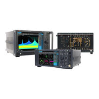
Keysight N8973B User & Programmers Manual (1175 pages)
Signal Analyzer IQ Analyzer Mode
Brand: Keysight
|
Category: Measuring Instruments
|
Size: 15 MB
Table of Contents
-
External2
-
External3
-
Screen Tabs48
-
Mode50
-
Measurement58
-
View58
-
Sequencer60
-
Screen Name63
-
89600 Vsa65
-
Add Screen66
-
Meas Bar68
-
Window Title72
-
Menu Panel81
-
User Menu92
-
Cancel Key93
-
Tab Key96
-
Local Button97
-
Control Bar98
-
Windows99
-
Undo/Redo100
-
File Functions104
-
File Explorer104
-
Help105
-
Status Bar106
-
Block Diagram114
-
View Editor116
-
Multiscreen137
-
Select Screen139
-
Fullscreen141
-
Views146
-
Normal146
-
Windows147
-
Amplitude148
-
Y Scale148
-
Ref Value148
-
Scale/DIV149
-
Ref Position149
-
Auto Scaling150
-
Attenuation150
-
Full Range Atten152
-
Mech Atten153
-
Elec Atten156
-
Mech Atten Step160
-
Range161
-
Mixer Lvl Offset163
-
I Range164
-
Q Range165
-
Q same as I166
-
Signal Path167
-
Presel Center167
-
Internal Preamp170
-
Lna171
-
Μw Path Control172
-
Settings186
-
Res BW186
-
Display188
-
View188
-
User View188
-
Rename User View190
-
Delete User View190
-
Annotation192
-
Graticule192
-
Trace Annotation193
-
Meas Bar193
-
Frequency195
-
Settings195
-
Center Frequency195
-
Span201
-
Marker203
-
Select Marker203
-
Settings204
-
Marker Frequency204
-
Marker Mode206
-
All Markers off207
-
Couple Markers207
-
Peak Search208
-
Marker Frequency208
-
Peak Search209
-
Next Peak210
-
Next Pk Right210
-
Next Pk Left210
-
Minimum Peak211
-
Pk-Pk Search211
-
Marker Delta212
-
Mkr->CF212
-
Mkr->Ref Lvl212
-
Pk Search Config214
-
Pk Threshold214
-
Pk Excursion215
-
Peak Search Mode218
-
Properties220
-
Marker Frequency220
-
Relative to220
-
Marker Trace221
-
Marker Function223
-
Band Span224
-
Band Left224
-
Band Right225
-
Marker to225
-
Mkr->CF226
-
Mkr->Ref Lvl226
-
Meas Setup227
-
Settings227
-
Average Mode228
-
Average Type228
-
Time Avg Num229
-
Auto Couple231
-
Meas Preset233
-
Filter234
-
Digital if BW234
-
Filter Type237
-
Filter BW238
-
Filter Alpha239
-
Fft240
-
FFT Window240
-
Length Ctrl241
-
Window Length241
-
FFT Length242
-
IF Path243
-
Apply EDC Preset250
-
Advanced251
-
ADC Dither257
-
LO Dither259
-
IF Gain260
-
IF Gain Offset262
-
Other if Gain263
-
Mixing Mode263
-
Invert Spectrum267
-
Sweep268
-
Sweep/Control268
-
Restart268
-
Pause/Resume271
-
Sweep/Measure272
-
Restart273
-
Pause/Resume276
-
Scale277
-
Ref Value277
-
Scale/DIV278
-
Ref Position278
-
Auto Scaling279
-
Recording279
-
Record Time279
-
Record Points280
-
Record281
-
Save as281
-
Quick Save281
-
Trace282
-
Settings282
-
Views285
-
RF Envelope285
-
I/Q Waveform286
-
Windows286
-
RF Envelope286
-
Metrics287
-
I/Q Waveform287
-
Amplitude288
-
Y Scale288
-
Ref Value288
-
Scale/DIV289
-
Scale Range290
-
Ref Position291
-
Auto Scaling292
-
Attenuation293
-
Full Range Atten295
-
Mech Atten296
-
Elec Atten299
-
Adjust Atten303
-
Mech Atten Step307
-
Range Auto/Man308
-
I Range309
-
Q Range311
-
Q same as I312
-
Range313
-
Mixer Lvl Offset315
-
Signal Path315
-
Presel Center316
-
Internal Preamp318
-
Lna320
-
Μw Path Control321
-
Settings335
-
Digital if BW335
-
Filter Type337
-
Filter BW339
-
Filter Alpha340
-
Display340
-
View340
-
View341
-
User View341
-
Rename User View342
-
Delete User View343
-
Annotation344
-
Graticule344
-
Trace Annotation345
-
Meas Bar346
-
Frequency348
-
Settings348
-
Center Frequency348
-
Marker354
-
Select Marker354
-
Settings355
-
Marker Time355
-
Marker Mode357
-
All Markers off358
-
Couple Markers358
-
Peak Search359
-
Marker Time359
-
Next Peak360
-
Minimum Peak360
-
Marker Delta360
-
Pk Search Config360
-
Marker Function362
-
Marker Time362
-
Interval Span363
-
Interval Left363
-
Interval Right364
-
Properties364
-
Marker Time364
-
Relative to364
-
Marker Trace365
-
Meas Setup366
-
Settings366
-
Average Mode367
-
Average Type367
-
Time Avg Num368
-
Meas Time369
-
Sample Rate370
-
Spur Avoidance371
-
Auto Couple374
-
Meas Preset376
-
IF Path376
-
Apply EDC Preset384
-
Advanced385
-
ADC Dither391
-
LO Dither392
-
IF Gain392
-
IF Gain Offset393
-
Other if Gain394
-
Mixing Mode395
-
Invert Spectrum397
-
Global399
-
Global EMC Std400
-
Restore Defaults401
-
Sweep401
-
Sweep/Control401
-
Restart401
-
Pause/Resume404
-
Sweep/Measure404
-
Scale407
-
Ref Value407
-
Scale/DIV407
-
Ref Position408
-
Auto Scaling408
-
Recording409
-
Record Time409
-
Record Points409
-
Record410
-
Save as410
-
Quick Save411
-
Trace411
-
Views415
-
Windows416
-
Meas Setup416
-
Streaming416
-
Start Streaming417
-
Stop Streaming417
-
Streaming Status418
-
Elapsed Time418
-
Remaining Time418
-
Total Samples419
-
Streamed Samples419
-
Scaling Factor419
-
Vita 49419
-
Context Packets420
-
Summary Packets420
-
All Other Menus421
-
System427
-
System428
-
Show System428
-
Show Hardware429
-
Show LXI429
-
Show Support ID430
-
Control Panel431
-
Web Browser432
-
Sounds432
-
I/O Config434
-
Gpib434
-
GPIB Address434
-
GPIB Controller434
-
Scpi Lan435
-
SCPI Telnet436
-
SCPI Socket436
-
SICL Server437
-
Hislip Server438
-
User IDN442
-
Lxi445
-
LAN Reset445
-
Power-On Mode454
-
Table of Modes455
-
Unload455
-
User Interface456
-
Menu Panel Tabs457
-
Display Theme457
-
Backlight458
-
Hints459
-
Touch On/Off460
-
Control Size460
-
Quick Save Mode460
-
Clock Format464
-
Language465
-
Power on467
-
Power on State467
-
Load FPGA473
-
Restore Defaults480
-
Input/Output480
-
I/O Config481
-
User Interface481
-
Power on481
-
Alignments482
-
Misc482
-
All483
-
Alignments485
-
Auto Align485
-
All but RF488
-
Alert488
-
Align Now490
-
Align Now All492
-
Align Now RF496
-
Align Source501
-
Align Receiver502
-
Align Fast502
-
Align lo Leakage503
-
Align if Cable503
-
Align lo Clock504
-
Frequency Range507
-
Enable509
-
Align Low Band510
-
Align High Band510
-
Timebase DAC525
-
User Value526
-
Advanced527
-
TDS Alignment534
-
Ogrf Preselector552
-
Alert555
-
Scheduler556
-
Schedule Setup556
-
Task556
-
Date/Time557
-
Hour558
-
Minute558
-
Recurrence558
-
Number of Weeks558
-
Day559
-
Licensing560
-
License Manager560
-
Network Licenses561
-
Borrow a License564
-
Security571
-
Diagnostics572
-
Service574
-
SCPI Recorder575
-
Recording Limit576
-
Play All576
-
Play Selected576
-
Copy577
-
Move up577
-
Move down577
-
Delete Row577
-
Delete All577
-
Preset585
-
Preset Dropdown588
-
Mode Preset589
Advertisement
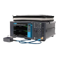
Keysight N8973B Service Manual (524 pages)
NFA Series
Brand: Keysight
|
Category: Measuring Instruments
|
Size: 15 MB
Table of Contents
-
1 Overview
13 -
-
-
Introduction69
-
-
-
-
Troubleshooting142
-
-
Troubleshooting206
-
-
-
-
Purpose270
-
-
-
Purpose280
-
-
-
Diagnostic Leds289
-
-
-
-
Disk Drive292
-
System Memory294
-
System Processor294
-
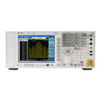
Keysight N8973B Manual (119 pages)
Signal Analyzers, Instrument Messages
Brand: Keysight
|
Category: Measuring Instruments
|
Size: 1 MB
Table of Contents
-
-
-
A-Series32
-
B-Series32
-
Status Bar34
-
-
Advertisement

Keysight N8973B Security Features And Document Of Volatility (46 pages)
PXE EMI Receiver UXA Signal Analyzer PXA Signal Analyzer MXA Signal Analyzer EXA Signal Analyzer CXA Signal Analyzer NFA Noise Figure Analyzer
Brand: Keysight
|
Category: Measuring Instruments
|
Size: 1 MB
Table of Contents
-
-
-
Option SF137
-
Option SF238