Sign In
Upload
Manuals
Brands
IEI Technology Manuals
Motherboard
WSB-9152
IEI Technology WSB-9152 Manuals
Manuals and User Guides for IEI Technology WSB-9152. We have
2
IEI Technology WSB-9152 manuals available for free PDF download: User Manual
IEI Technology WSB-9152 User Manual (258 pages)
Brand:
IEI Technology
| Category:
Single board computers
| Size: 12.27 MB
Table of Contents
Table of Contents
7
1 Introduction
21
Introduction
22
Model Variations
22
WSB-9152 Benefits
23
WSB-9152 Features
23
Table 1-1: WSB-9152 Model Variations
23
Wsb-9152 Overview
24
WSB-9152 Overview Photo
24
WSB-9152 Peripheral Connectors and Jumpers
24
Figure 1-2: WSB-9152 Overview [Front View]
24
Technical Specifications
25
Table 1-2: Technical Specifications
27
2 Detailed Specifications
28
Overview
29
Dimensions
29
Board Dimensions
29
Figure 2-1: WSB-9152 Dimensions (MM)
29
External Interface Panel Dimensions
30
Figure 2-2: External Interface Panel Dimensions (MM)
30
Data Flow
31
Figure 2-3: Data Flow Block Diagram
31
Compatible Processors
32
Compatible Processor Overview
32
Figure 2-4: Socket 479
32
Intel 915GME Northbridge Chipset
33
Figure 2-5: Northbridge
33
Table 2-1: Compatible Processors
33
Intel ® 915GME Memory Support
34
Intel ® 915GME Integrated Graphics
35
Intel 915GME Analog CRT Support
35
Figure 2-6: 240-Pin DDR2 DIMM Socket
35
Intel 915GME LVDS Support
36
Figure 2-7: LVDS Connector
36
Chrontel 7307C
37
Figure 2-8: DVI Controller
37
Intel ® 915GME Direct Media Interface (DMI)
38
Intel ® Ich6M Southbridge Chipset
38
Figure 2-9: Intel ICH6M Southbridge
38
Figure 2-10: Audio Header
39
Intel ® ICH6M Azalia and AC '97 Controllers
39
Figure 2-11: IDE Interface
40
Intel ® ICH6M IDE Interface
40
Figure 2-12: Onboard USB Implementation
41
Table 2-2: Supported HDD Specifications
41
Figure 2-13: Broadcom BCM5787M Gbe Controllers
42
Pcie Gbe
42
Intel ® ICH6M Low Pin Count (LPC) Interface
41
Intel ® ICH6M PCI Interface
41
Intel ® ICH6M Real Time Clock
43
Figure 2-14: SATA Ports
44
Intel ® ICH6M SATA Controller
44
Figure 2-15: SATA II Ports
45
Intel ® ICH6M USB Controller
45
Jmicron JMB363 SATA II Controller
45
Lpc Bus Components
46
BIOS Chipset
46
Figure 2-16: Onboard USB Implementation
46
Super I/O Chipset
47
Figure 2-17: BIOS Chipset
47
Figure 2-18: Super I/O Chipset
47
Super I/O 16C550 Uarts
48
Super I/O Floppy Disk Drive (FDD) Controller
48
Super I/O LPC Interface
48
Super I/O Smart Fan Control System
48
Super I/O Parallel Port (LPT)
49
Super I/O Keyboard and Mouse Controller
50
Environmental and Power Specifications
50
System Monitoring
50
Operating Temperature and Temperature Control
51
Power Consumption
51
Expansion Options
51
Table 2-3: Power Consumption
51
IEI Expansion PCI/PX Backplanes
52
IEI Chassis
53
Table 2-4: Compatible IEI Picoe Backplanes
53
Table 2-5: Compatible IEI Chassis
54
3 Unpacking
55
Anti-Static Precautions
56
Unpacking Precautions
56
Unpacking Checklist
57
Package Contents
57
Table 3-1: Package List Contents
58
Optional Items
59
Table 3-2: Optional Items
59
4 Connector Pinouts
60
Peripheral Interface Connectors
61
Figure 4-1: Connector and Jumper Locations
61
External Interface Panel Connectors
62
Table 4-1: Peripheral Interface Connectors
62
Table 4-2: Rear Panel Connectors
62
Internal Peripheral Connectors
63
Audio Connector (9-Pin)
63
Figure 4-2: Audio Connector Location (9-Pin)
63
Backlight Inverter Connector
64
Figure 4-3: Panel Backlight Connector Pinout Locations
64
Table 4-3: Audio Connector Pinouts (9-Pin)
64
Backplane to Mainboard Connector
65
Table 4-4: Panel Backlight Connector Pinouts
65
Fan Connector (+12 V, 4-Pin)
66
Figure 4-4: Backplane to Mainboard Connector Location
66
Table 4-5: Backplane to Mainboard Connector Pinouts
66
CPU Power Connector
67
Figure 4-5: +12 V Fan Connector Location
67
Table 4-6: +12 V Fan Connector Pinouts
67
Digital Input/Output (DIO) Connector
68
Figure 4-6: ATX Power Connector Location
68
Table 4-7: ATX Power Connector Pinouts
68
Figure 4-7: DIO Connector Locations
69
Table 4-8: DIO Connector Connector Pinouts
69
Digital Video Interface (DVI) Connector
70
Figure 4-8: DVI Connector Location
70
Floppy Disk Connector (34-Pin)
71
Table 4-9: DVI Connector Pinouts
71
Figure 4-9: 34-Pin FDD Connector Location
72
Front Panel Connector (14-Pin)
73
Table 4-10: 34-Pin FDD Connector Pinouts
73
IDE Connector (40-Pin)
74
Figure 4-10: Front Panel Connector Pinout Locations
74
Table 4-11: Front Panel Connector Pinouts
74
Figure 4-11: IDE Device Connector Locations
75
Keyboard Connector
76
Table 4-12: IDE Connector Pinouts
76
LVDS LCD Connector
77
Figure 4-12: Keyboard Connector Location
77
Table 4-13: Keyboard Connector Pinouts
77
Figure 4-13: LVDS LCD Connector Pinout Locations
78
Parallel Port Connector
79
Table 4-14: LVDS LCD Port Connector Pinouts
79
Figure 4-14: Parallel Port Connector Location
80
Pcie Mini Card Connector
81
Table 4-15: Parallel Port Connector Pinouts
81
Figure 4-15: PCI Slot Location
82
SATA Drive Connectors
83
Figure 1-1: WSB-9152
83
Table 4-16: Pcie Mini Card Connector
83
Serial Port Connector (COM 2)
84
Figure 4-16: SATA Drive Connector Locations
84
Table 4-17: SATA Drive Connector Pinouts
84
Figure 4-17: COM Connector Pinout Locations
85
Table 4-18: COM Connector Pinouts
85
USB Connectors (Internal)
86
Figure 4-18: USB Connector Pinout Locations
86
External Peripheral Interface Connector Panel
87
Keyboard/Mouse Connector
87
Figure 4-19: WSB-9152 External Peripheral Interface Connector
87
Table 4-19: USB Port Connector Pinouts
87
LAN Connectors
88
Figure 4-20: PS/2 Pinout and Configuration
88
Table 4-20: Keyboard Connector Pinouts
88
USB Connector
89
Figure 4-21: RJ-45 Ethernet Connector
89
Table 4-21: LAN Pinouts
89
Table 4-22: RJ-45 Ethernet Connector Leds
89
VGA Connector
90
Figure 4-22: VGA Connector
90
Table 4-23: USB Port Pinouts
90
Table 4-24: VGA Connector Pinouts
90
5 Installation
91
Anti-Static Precautions
92
Installation Considerations
92
Installation Notices
93
Installation Checklist
93
Cpu, Cpu Cooling Kit and DIMM Installation
94
Socket 479 CPU Installation
95
Figure 5-1: Make Sure the CPU Socket Retention Screw Is Unlocked
95
Figure 5-2: Lock the CPU Socket Retention Screw
96
Cooling Kit CF-479B-RS Installation
97
Figure 5-3: IEI CF-479B-RS Cooling Kit
97
Figure 5-4: Cooling Kit Support Bracket
98
Figure 5-5: Connect the Cooling Fan Cable
98
DIMM Installation
99
Figure 5-6: Installing a DIMM
99
Jumper Settings
100
Table 5-1: Jumpers
100
Clear CMOS Jumper
101
Figure 5-7: Jumpers
101
CPU Frequency Selection Jumper
102
Figure 5-8: Clear CMOS Jumper
102
Table 5-2: Clear CMOS Jumper Settings
102
Figure 5-9: CPU Frequency Selection Jumper
103
LVDS Panel Resolution Jumper
103
Table 5-3: CPU Frequency Selection Settings
103
Figure 5-10: LVDS Panel Resolution Jumper
104
LVDS Voltage Selection
104
Table 5-4: LVDS Panel Resolution Settings
104
Figure 5-11: LVDS Voltage Selection Jumper Location
105
Table 5-5: LVDS Voltage Selection Jumper Settings
105
Chassis Installation
106
Airflow
106
Backplane Installation
106
CPU Card Installation
107
Internal Peripheral Device Connections
107
Peripheral Device Cables
107
Table 5-6: IEI Provided Cables
107
IDE Cable Connection
108
Figure 5-12: IDE Cable Connection
108
Channel Audio Kit Installation
109
Channel Audio Kit Installation
110
Figure 5-13: 5.1 Channel Audio Kit
110
Figure 5-14: 7.1 Channel Audio Kit
111
FDD Cable Connection
112
Figure 5-15: FDD Cable Connection
112
Parallel Port Cable
113
Figure 5-16: LPT Cable Connection
113
Dual RS-232 Cable Connection
114
Figure 5-17: Connect the LPT Device
114
SATA Drive Connection
115
Figure 5-18: Dual RS-232 Cable Installation
115
Figure 5-19: SATA Drive Cable Connection
116
Wafer-To-PS/2 Cable (Keyboard/Mouse Installation)
117
Figure 5-20: SATA Power Drive Connection
117
External Peripheral Interface Connection
118
Figure 5-21: Keyboard/Mouse Cable Connection
118
Figure 5-22: LAN Connection
119
LAN Connection (Single Connector)
119
Figure 5-23: USB Device Connection
120
USB Device Connection
120
VGA Monitor Connection
120
Figure 5-24: VGA Connector
121
6 Ami Bios
122
Introduction
123
Starting Setup
123
Using Setup
123
Getting Help
124
Unable to Reboot after Configuration Changes
124
BIOS Menu Bar
124
Table 6-1: BIOS Navigation Keys
124
Main
125
Advanced
126
CPU Configuration
128
IDE Configuration
129
IDE Master, IDE Slave
131
Floppy Configuration
136
Super IO Configuration
137
Hardware Health Configuration
140
Remote Access Configuration
141
USB Configuration
145
Pci/Pnp
147
Boot
149
Boot Settings Configuration
150
Boot Device Priority
152
Hard Disk Drives
153
Removable Drives
155
CD/DVD Drives
156
Security
158
Chipset
159
Northbridge Configuration
161
Southbridge Chipset Configuration
163
Power
164
Advanced Power Configuration
165
Exit
167
7 Raid Setup
170
Introduction
171
Precautions
171
Features and Benefits
172
Accessing the Jmicron RAID Utility
172
Creating Araid Array
174
Deleting Araid Array
177
Revert a Hard Drive to Non-RAID
179
Solve Mirror Conflict
180
Rebuild Mirror Drive
181
Save and Exit Setup
182
Exit Without Saving
183
Raid Options
185
RAID 0 Striping - for Performance
185
RAID 1 Mirror - for Redundancy
186
Jbod
186
8 Driver Installation
187
Available Software Drivers
188
Driver CD Auto-Run
188
Figure 8-1: Introduction Screen
189
Chipset Driver Installation
190
Figure 8-2: Available Drivers
190
Figure 8-3: Chipset Driver Installation Program
191
Figure 8-4: Chipset Driver Installation Welcome Screen
191
Figure 8-5: Chipset Driver Installation License Agreement
192
Figure 8-6: Chipset Driver Readme File Information
192
Intel Graphics Media Accelerator Driver
193
Figure 8-7: Chipset Driver Installation Complete
193
Figure 8-8: Select the Operating System
194
Figure 8-9: VGA Driver
194
Figure 8-10: GMA Driver Readme File
195
Figure 8-11: GMA Driver File Extraction
196
Figure 8-12: GMA Driver Installation Welcome Screen
196
Figure 8-13: GMA Driver License Agreement
197
Figure 8-14: GMA Driver Installing Notice
197
Figure 8-15: GMA Driver Installation Complete
198
Pcie Gbe Installation
199
Figure 8-16: Access Windows Control Panel
199
Figure 8-17: Double Click the System Icon
200
Figure 8-18: Click the Device Manager Button
201
Figure 8-19: Device Manager List
202
Figure 8-20: Hardware Update Wizard
203
Figure 8-21: Automatic or Manual Installation
203
Figure 8-22: Select Driver Location
204
Figure 8-23: Select Driver Location
205
Figure 8-24: Install from Disk
205
Figure 8-25: Install from Disk
206
Figure 8-26: Install from Disk
206
Hd Audio Driver (Alc883) Installation
207
BIOS Setup
207
Driver Installation
207
Figure 8-27: 4-AUDIO\AC-Kit883Hd\Windows Folder
208
Figure 8-28: HD Audio Driver Setup Extracting Files
209
Figure 8-29: HD Audio Driver Setup Welcome Screen
209
Ac`97 Audio Driver (Alc665) Installation
210
BIOS Setup
210
Figure 8-30: HD Audio Driver Installation Complete
210
Driver Installation
211
Figure 8-31: CD 4-AUDIO\AC-Kit08R\Windows Folder
211
Figure 8-32: AC`97 Audio Driver Install Shield Wizard Starting
212
Figure 8-33: AC`97 Audio Driver Setup Preparation
212
Figure 8-34: AC`97 Audio Driver Welcome Screen
213
Figure 8-35: AC`97 Audio Driver Digital Signal
213
Figure 8-36: AC`97 Audio Driver Installation Begins
214
Figure 8-37: AC`97 Audio Driver Installation Complete
214
Sata Driver Installation
215
Figure 8-38: CD Folder 5-Sata\Jmb36X\R1.17.11\Win2K_Xp
216
Figure 8-39: SATA Driver Install Shield Wizard Starting
217
Figure 8-40: SATA Driver Setup Preparation
217
Figure 8-41: SATA Driver Welcome Screen
218
Figure 8-42: SATA Driver Digital Signature
218
Figure 8-43: SATA Driver Installation Begins
219
Figure 8-44: SATA Driver Installation Complete
219
Ide Controller Installation
220
Figure 8-45: Access Windows Control Panel
220
Figure 8-46: Double Click the System Icon
221
Figure 8-47: Click the Device Manager Button
222
Figure 8-48: Device Manager List
223
Figure 8-49: Hardware Update Wizard
224
Figure 8-50: Automatic or Manual Installation
224
Figure 8-51: Select Driver Location
225
Figure 8-52: Select Driver Location
226
Figure 8-53: Install from Disk
226
Figure 8-54: Locate File
227
Figure 8-55: Install from Disk
227
ABIOS Options
228
B Terminology
231
C Digital I/O Interface
235
Introduction
236
Dio Connector Pinouts
236
Assembly Language Samples
237
Enable the DIO Input Function
237
Enable the DIO Output Function
237
D Watchdog Timer
238
E Address Mapping
241
Io Address Map
242
St Mb Memory Address Map
243
Irq Mapping Table
243
Dma Channel Assignments
244
F Compatibility
245
Compatible Operating Systems
246
Compatible Processors
246
Compatible Memory Modules
247
G Hazardous Materials Disclosure
248
Advertisement
IEI Technology WSB-9152 User Manual (196 pages)
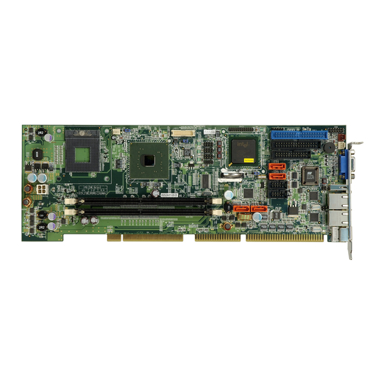
Socket 479 Pentium M 533MHz FSB CPU Card with VGA, PCIe GbE, USB2.0, SATA/SATA II
Brand:
IEI Technology
| Category:
Motherboard
| Size: 5.26 MB
Table of Contents
Table of Contents
3
1 Introduction
15
Table 1-1: WSB-9152 Model Variations
16
Figure 1-1: WSB-9152 CPU Card Overview
18
Technical Specifications
19
Wsb-9152 Cpu Card Overview
16
WSB-9152 Model Variations
16
WSB-9152 CPU Card Applications
16
WSB-9152 CPU Card Benefits
16
WSB-9152 CPU Card Features
17
Wsb-9152 Cpu Card Overview
18
WSB-9152 CPU Card Connectors
18
Table 1-2: Technical Specifications
20
2 Detailed Specifications
21
Compatible Iei Backplanes
22
Cpu Support
22
Supported Pentium® M Cpus
22
Supported Celeron® M Cpus
23
Table 2-1: Supported Pentium® M Cpus
23
Table 2-2: Supported Celeron® M Cpus
24
Figure 2-1: Data Flow Block Diagram
25
Analog VGA
26
Digital LVDS
26
Gma 900
26
Graphics Support
26
Optional Digital Visual Interface (DVI)
26
Ethernet Connection
27
Memory Support
27
Pci Bus Interface Support
27
PCI Express (Pcie) Ethernet
27
Drive Interfaces
28
Gbe Ethernet
28
SATA Drives
28
Floppy Disk Drive (FDD)
29
HDD Interfaces
29
SATA-II and RAID Functionality (SATA3 and SATA4 Only)
29
Infrared Data Association (Irda) Interface
30
Real Time Clock
30
Serial Ports
30
System Monitoring
30
Usb Interfaces
30
Bios
31
Operating Temperature and Temperature Control
31
Optional Audio Interface
31
Power Consumption
31
Optional Accessory Items
32
Package Contents
32
Packaged Contents and Optional Accessory Items
32
Special Items
32
Data Flow
25
Onboard Chipsets
24
Northbridge and Southbridge Chipsets
24
Intel ® 915GM Northbridge Chipset
24
Intel ® ICH6-M Southbridge Chipset
24
Table 2-3: Power Consumption
32
3 Connectors and Jumpers
35
Figure 3-1: Connector and Jumper Locations
36
Peripheral Interface Connectors
36
WSB-9152 CPU Card Layout
36
Peripheral Interface Connectors
37
Onboard Jumpers
38
Rear Panel Connectors
38
Table 3-2: Peripheral Interface Connectors
38
Table 3-1: Peripheral Interface Connectors
38
Internal Peripheral Connectors
39
FDD Connector
39
Table 3-3: Onboard Jumpers
39
Figure 3-3: IDE Connector Location
42
Figure 3-4: COM Port Locations
43
Table 3-6: Internal COM Port Connector Pinouts
43
Table 3-7: LPT Connector Pinouts
44
Figure 3-5: LPT Connector Location
45
Internal USB Connectors
45
Figure 3-6: USB Port Connector Location
46
Table 3-8: USB Port Connector Pinouts
46
Cooling Fan Connectors
47
Table 3-9: Cooling Fan Connector Pinouts
47
Backplane to Mainboard ATX Connector
48
Figure 3-7: Cooling Fan Connector Locations
48
Figure 3-8: ATXCTL1 Connector Locations
49
Table 3-10: CN7 Connector Pin Outs
49
System Front Panel Connector
50
Table 3-11: System Panel Connector Pinouts
50
Figure 3-9: System Panel Connector Location
51
Irda Connector
51
Figure 3-10: Irda Connector Location
52
Table 3-12: Irda Connector Pinouts
52
SATA Drive Connectors
53
Table 3-13: SATA Connector Pinouts
53
Figure 3-11: SATA Connector Locations
54
DVI (Digital Visual Interface) Connector
55
Table 3-14: DVI Connector Pinouts
55
Figure 3-12: DVI1 Connector Location
56
LVDS Connector
56
Table 3-15: LVDS Connector Pinouts
57
Figure 3-13: LVDS LCD Panel Connection Port
58
Inverter Control
58
Figure 3-14: J1 Inverter Control
59
LAN State LED Connector
59
Table 3-16: Inverter Connector Pinouts
59
Figure 3-15: J_LANLED Connector Locations
60
Table 3-17: J_LANLED Connector Pinouts
60
AC'97 Connector
61
Table 3-18: CN9 Connector Pinouts
61
Figure 3-16: CN9 Connector Location
62
Keyboard Connector
62
Table 3-19: KB1 Connector Pinouts
63
ATX-12V Power Source Connector
64
Figure 3-17: KB1 Connector Location
64
Figure 3-18: ATX Connector Location
64
Table 3-20: CN100 Connector Pinouts
64
External (Rear Panel) Connectors
65
Figure 3-19: WSB-9152 CPU Card Rear Panel
65
PS/2 Connector
65
Ethernet Connectors
66
Figure 3-20: PS/2 Pinout Locations
66
Table 3-21: PS/2 Pinouts
66
Table 3-22: USB Connectors
66
USB Connector
66
Figure 3-21: RJ-45 Ethernet Connector
67
Table 3-23: RJ-45 Ethernet Connector Pinouts
67
Table 3-24: RJ-45 Ethernet Connector Leds
67
VGA Connector
67
Onboard Jumpers
68
Table 3-25: VGA Connector Pinouts
68
Figure 3-23: Jumper Locations
69
Table 3-26: Jumpers
69
LVDS Panel Voltage Jumper
70
Reset CMOS Jumper
70
Table 3-27: JP1 Jumper Settings
70
FSB Selection Jumper
71
Figure 3-2: FDD Connector Location
40
Table 3-4: FDD Connector Pinouts
40
Table 3-5: IDE Connector Pinouts
41
COM Ports
42
Parallel Port
44
IDE Connectors
41
Table 3-28: JP2 Jumper Settings
71
Table 3-29: JP3 Jumper Settings
71
4 Installation and Configuration
73
Installation Considerations
74
Installation Notices
74
Unpacking
75
Unpacking Precautions
75
Checklist
75
Wsb-9152 Cpu Card Installation
76
CPU Installation
77
Figure 4-1: Make Sure the CPU Socket Retention Screw Is Unlocked
78
Cooling Kit (CF-518-RS) Installation
79
Figure 4-3: IEI CF-518-RS Cooling Kit
79
Figure 4-4: Securing the Cooling Kit
80
Figure 4-5: Connect the Cooling Fan Cable
81
Table 4-1: IEI Provided Cables
82
Floppy Drive Connector (FDD1)
83
Jumper Configuration
83
Chassis Installation
84
Ethernet Connection
84
LCD Panel Connection
84
Rear Panel Connectors
84
USB Connection
84
DIMM Module Installation
82
Peripheral Device Connection
82
IDE Disk Drive Connector (IDE1)
82
Figure 4-2: Lock the CPU Socket Retention Screw
79
DIMM Module Installation
81
Purchasing the Memory Module
81
5 Award Bios Setup
85
Introduction
86
Starting Setup
86
Using Setup
86
Getting Help
87
Unable to Reboot after Configuration Changes
87
Main BIOS Menu
87
Table 5-1: BIOS Navigation Keys
87
Standard Cmos Features
90
IDE Channel Master
93
Advanced Bios Features
95
CPU Feature
103
Hard Disk Boot Priority
106
Advanced Chipset Features
107
Integrated Peripherals
114
Onchip IDE Device
114
Onboard Device
118
Superio Device
120
Power Management Setup
127
Pnp/Pci Configurations
135
Pc Health Status
140
6 Software Drivers
143
Available Software Drivers
144
Chipset Driver Installation
144
Figure 6-1: Chipset Driver Installation Welcome Screen
145
Figure 6-2: Chipset Driver Installation License Agreement
146
Figure 6-3: Chipset Driver Readme File Information
147
Figure 6-4: Chipset Driver Installation Complete
148
Intel Graphics Media Accelerator Driver
148
Figure 6-5: GMA Driver Installation Welcome Screen
149
Figure 6-7: GMA Driver Installing Notice
150
Figure 6-6: GMA Driver License Agreement
150
Figure 6-8: GMA Driver Installation Complete
151
Realtek Audio Driver Installation
151
Figure 6-9: Audio Driver Install Shield Wizard Starting
152
Figure 6-10: Audio Driver Setup Prerparation
152
Figure 6-11: Audio Driver Welcome Screen
153
Figure 6-12: Audio Driver Software Configuration
153
Figure 6-13: Audio Driver Digital Signal
154
Figure 6-14: Audio Driver Installation Begins
155
Marvell Gigabit Ethernet Controller Driver Installation
156
Figure 6-15: Audio Driver Installation Complete
156
Figure 6-16: Ethernet Controller Driver Install Shield Wizard Starting
157
Figure 6-17: Ethernet Controller Driver Installation Welcome Screen
157
Figure 6-18: Ethernet Driver License Agreement
158
Figure 6-19: GMA Driver Installing Notice
159
Figure 6-20: Ethernet Driver Is Installed
160
Figure 6-21: Ethernet Driver Installation Confirmation
161
Abios Configuration Options
163
Bios Configuration Options
163
O Ptions
164
Bwatchdog Timer
169
Caddress Mapping
173
Io Address Map
174
St Mb Memory Address Map
174
Addres Map
174
Irq Mapping Table
175
Dma Channel Assignments
175
Dexternal Ac'97 Audio Codec
177
Introduction
178
Physical Connection
179
Driver Installation
180
Sound Effect Configuration
181
Sound Effect
182
Environment Simulation
182
Karaoke Mode
183
Equalizer Selection
184
Speaker Configuration
185
Speaker Test
186
S/PDIF-In & S/PDIF-Out
187
Connector Sensing
188
Hrtf Demo
191
Microphone Effect
191
General
192
Index
193
Advertisement
Related Products
IEI Technology WSB-G41A
IEI Technology WSB-Q354
IEI Technology WSB-9454
IEI Technology WSB-9452
IEI Technology WSB-G41A-R11
IEI Technology WSB-H810
IEI Technology WAFER-PV-D5252
IEI Technology WAFER-LX-CLIENT-CENET050
IEI Technology WAFER-CV-N26001
IEI Technology WAFER-LX Series
IEI Technology Categories
Motherboard
Touch Panel
Computer Hardware
Single board computers
Desktop
More IEI Technology Manuals
Login
Sign In
OR
Sign in with Facebook
Sign in with Google
Upload manual
Upload from disk
Upload from URL