Table of Contents
Advertisement
Advertisement
Table of Contents

Related Manuals for IEI Technology WSB-9152


Summary of Contents for IEI Technology WSB-9152
- Page 1 WSB-9152 CPU Card...
- Page 2 WSB-9152 CPU Card REVISION HISTORY Title WSB-9152 Intel® Pentium® M Socket 479 CPU card Revision Number Description Date of Issue Initial release March 2006 1.01 Modified JP1 information April 2007 COPYRIGHT NOTICE The information in this document is subject to change without prior notice in order to improve reliability, design and function and does not represent a commitment on the part of the manufacturer.
-
Page 3: Table Of Contents
INTRODUCTION....................15 WSB-9152 CPU ..............16 CARD VERVIEW 1.1.1 WSB-9152 Model Variations..............16 1.1.2 WSB-9152 CPU Card Applications ............16 1.1.3 WSB-9152 CPU Card Benefits ..............16 1.1.4 WSB-9152 CPU Card Features ..............17 WSB-9152 CPU C ..............18 VERVIEW 1.2.1... - Page 4 2.20.3 Optional Accessory Items................32 CONNECTORS AND JUMPERS ................. 35 .............. 36 ERIPHERAL NTERFACE ONNECTORS 3.1.1 WSB-9152 CPU card Layout ..............36 3.1.2 Peripheral Interface Connectors .............. 37 3.1.3 Rear Panel Connectors ................38 3.1.4 Onboard Jumpers..................38 ..............39...
- Page 5 WSB-9152 CPU Card 3.2.13 Inverter Control ..................58 3.2.14 LAN State LED Connector ................ 59 3.2.15 AC’97 Connector ..................61 3.2.16 Keyboard Connector ................. 62 3.2.17 ATX-12V Power Source Connector............64 ............65 XTERNAL ANEL ONNECTORS 3.3.1 PS/2 Connector ..................65 3.3.2...
- Page 6 WSB-9152 CPU Card AWARD BIOS SETUP ................... 85 ....................86 NTRODUCTION 5.1.1 Starting Setup .................... 86 5.1.2 Using Setup ....................86 5.1.3 Getting Help....................87 5.1.4 Unable to Reboot After Configuration Changes........87 5.1.5 Main BIOS Menu ..................87 CMOS F ................
- Page 7 WSB-9152 CPU Card DMA C ............... 175 HANNEL SSIGNMENTS EXTERNAL AC’97 AUDIO CODEC ..............177 ....................178 NTRODUCTION ................... 179 HYSICAL ONNECTION ..................180 RIVER NSTALLATION ..............181 OUND FFECT ONFIGURATION ....................182 OUND FFECT ................182 NVIRONMENT IMULATION ....................183 ARAOKE ..................
- Page 8 WSB-9152 CPU Card List of Figures Figure 1-1: WSB-9152 CPU card Overview ...............18 Figure 2-1: Data Flow Block Diagram................25 Figure 3-1: Connector and Jumper Locations ............36 Figure 3-2: FDD Connector Location ................40 Figure 3-3: IDE Connector Location................42 Figure 3-4: COM Port Locations ................43 Figure 3-5: LPT Connector Location .................45...
- Page 9 WSB-9152 CPU Card Figure 4-5: Connect the cooling fan cable ...............81 Figure 6-1: Chipset Driver Installation Welcome Screen ........145 Figure 6-2: Chipset Driver Installation License Agreement......... 146 Figure 6-3: Chipset Driver Readme File Information ..........147 Figure 6-4: Chipset Driver Installation Complete..........148 Figure 6-5: GMA Driver Installation Welcome Screen ..........
- Page 10 WSB-9152 CPU Card List of Tables Table 1-1: WSB-9152 Model Variations ..............16 Table 1-2: Technical Specifications ................20 Table 2-1: Supported Pentium® M CPUs..............23 Table 2-2: Supported Celeron® M CPUs..............24 Table 2-3: Power Consumption .................32 Table 3-1: Peripheral Interface Connectors..............38 Table 3-2: Peripheral Interface Connectors..............38 Table 3-3: Onboard Jumpers ..................39...
- Page 11 WSB-9152 CPU Card Table 3-25: VGA Connector Pinouts .................68 Table 3-26: Jumpers....................69 Table 3-27: JP1 Jumper Settings................70 Table 3-28: JP2 Jumper Settings................71 Table 3-29: JP3 Jumper Settings................71 Table 4-1: IEI Provided Cables...................82 Table 5-1: BIOS Navigation Keys................87 0-11...
- Page 12 WSB-9152 CPU Card List of BIOS Menus BIOS Menu 1: Award BIOS CMOS Setup Utility ............88 BIOS Menu 2: Standard CMOS Features ..............90 BIOS Menu 3: IDE Channel Master ................93 BIOS Menu 4: Advanced BIOS Features..............96 BIOS Menu 5: CPU Feature ..................103 BIOS Menu 6: Hard Disk Boot Priority ..............
- Page 13 WSB-9152 CPU Card Glossary AC ’97 Audio Codec 97 Hard Disk Drive ACPI Advanced Configuration and Integrated Data Electronics Power Interface Input/Output Advanced Power Management ICH4 I/O Controller Hub 4 ARMD ATAPI Removable Media Device Cache Level 1 Cache ASKIR...
- Page 14 WSB-9152 CPU Card THIS PAGE IS INTENTIONALLY LEFT BLANK ® Technology, Corp. 0-14...
-
Page 15: Introduction
WSB-9152 CPU Card Chapter Introduction 1-15... -
Page 16: Wsb-9152 Cpu Card Overview
WSB-9152 CPU Card WSB-9152 CPU card Overview The PICMG 1.0 form factor WSB-9152 socket 479 Pentium M CPU card is fully equipped with a high performance processor and advanced multi-mode I/Os. The WSB-9152 is designed for system manufacturers, integrators, and VARs that want performance, reliability, and quality at a reasonable price. -
Page 17: Wsb-9152 Cpu Card Features
WSB-9152 CPU Card 1.1.4 WSB-9152 CPU Card Features Some of the WSB-9152 CPU card features are listed below: PICMG 1.0 compliant RoHS compliant Socket 479 Intel® Pentium M and Intel® Celeron M CPUs supported Maximum front side bus (FSB) speed of 533MHz supported... -
Page 18: Wsb-9152 Cpu Card Overview
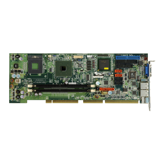
WSB-9152 CPU Card Overview Figure 1-1: WSB-9152 CPU card Overview 1.2.1 WSB-9152 CPU card Connectors The WSB-9152 CPU card has the following connectors onboard: 1 x ATX 12V connector 1 x CPU cooling fan connector 1 x System cooling fan connector... -
Page 19: Technical Specifications
The location of these connectors on the CPU card can be seen in Figure 1-1. These connectors are fully described in Chapter 3. 1.2.2 Technical Specifications WSB-9152 CPU card technical specifications are listed in Table 1-2. Detailed descriptions of each specification can be found in Chapter 2 Detailed Specifications. SPECIFICATION ®... -
Page 20: Table 1-2: Technical Specifications
WSB-9152 CPU Card transfer rates and RAID 0 and RAID 1 functions (SATA3 and SATA4) HDD Interface One IDE channel supports two Ultra ATA 100/66/33 devices Floppy Disk Drive (FDD) Supports FDD USB Interfaces Seven USB 2.0 connectors supported (Real X1, Front... -
Page 21: Detailed Specifications
WSB-9152 CPU Card Chapter Detailed Specifications 1-21... -
Page 22: Compatible Iei Backplanes
(M) Intel ® Pentium ® M processors and Intel ® Celeron ® M processors 2.2.1 Supported Pentium® M CPUs Table 2-1 lists the Intel ® Pentium ® M processors supported by the WSB-9152 CPU card. All the Intel ® Pentium ® M processors support Enhanced Intel SpeedStep® Technology. -
Page 23: Supported Celeron® M Cpus
400MHz 130nm 1.30GHz 400MHz Table 2-1: Supported Pentium® M CPUs 2.2.2 Supported Celeron® M CPUs Table 2-2 lists the Intel ® Celeron ® M processors supported by the WSB-9152 CPU card. Processor Number Power Architecture L2 Cache Speed Execute Disable Bit... -
Page 24: Onboard Chipsets
WSB-9152 CPU Card Normal 130nm 512KB 1.50GHz 400MHz 130nm 512KB 900MHz 400MHz Normal 130nm 512KB 1.40GHz 400MHz Normal 130nm 512KB 1.30GHz 400MHz Normal 130nm 512KB 1.20GHz 400MHz Table 2-2: Supported Celeron® M CPUs Onboard Chipsets 2.3.1 Northbridge and Southbridge Chipsets The following chipsets are preinstalled on the board: ®... -
Page 25: Data Flow
WSB-9152 CPU Card Supports ACPI power management Integrates a SATA controller that controls two SATA-I channels (SATA1 and SATA2) with transfer rates up to 150MB/s and independent DMA operation Supports Ultra ATA 100/66/33 with an integrated IDE controller Supports eight USB 2.0 ports but only seven are implemented on the WSB-9152 CPU card. -
Page 26: Graphics Support
WSB-9152 CPU Card Graphics Support ® 2.5.1 Intel GMA 900 ® ® The Intel GMA 900 integrated on the Intel 915GM chipset has the following features. 333MHz 2D display core: 1.05V VCC: 133/190/200MHz 333MHz 3D Render core: 1.05V VCC: 166/190/200MHz ®... -
Page 27: Memory Support
WSB-9152 CPU Card Memory Support The WSB-9152 CPU has two 240-pin dual inline memory module (DIMM) sockets and supports up to two unbuffered DDR2 DIMMs with the following specifications: Maximum RAM: 2GB (1GB module in each slot) DIMM Transfer Rates: 533MHz, 400MHz Up to 8.5 GB/sec memory bandwidth... -
Page 28: Gbe Ethernet
WSB-9152 CPU Card 2.8.2 GbE Ethernet The two GbE controllers (Marvell Yukon 88E8053) on the WSB-9152 CPU card connect to two 10/100/1000Mb/s Ethernet RJ-45 LAN ports on the rear panel. The GbE controllers come with the following features: Dual 1Gb/s external LAN connectivity... -
Page 29: Hdd Interfaces
Ultra ATA/66, with data transfer rates up to 66MB/s Ultra ATA/100, with data transfer rates up to 100MB/s 2.9.3 Floppy Disk Drive (FDD) The WSB-9152 CPU card supports a single FDD. The following FDD formats are compatible with the board. 5.25”: 360KB and 1.2MB 3.5”: 720KB, 1.44MB and 2.88MB... -
Page 30: Serial Ports
If you want to use the IrDA port, you have to configure SIR or ASKIR mode in the BIOS under Super IO devices. The normal RS-232 COM 2 will be disabled. 2.15 USB Interfaces The WSB-9152 CPU card has seven USB interfaces, six internal and one external. The USB interfaces support USB2.0. ®... -
Page 31: Bios
WSB-9152 CPU Card 2.16 BIOS The WSB-9152 CPU card uses a licensed copy of Phoenix Award BIOS. The features of the flash BIOS used are listed below: SMIBIOS (DMI) compliant Console redirection function support PXE (Pre-Boot Execution Environment ) support USB booting support 2.17 Operating Temperature and Temperature Control... -
Page 32: Packaged Contents And Optional Accessory Items
Table 2-3: Power Consumption 2.20 Packaged Contents and Optional Accessory Items 2.20.1 Package Contents When you unpack the WSB-9152 CPU card you should find the following components. 1 x WSB-9152 single board computer 1 x mini jumper pack 1 x ATA 66/100 flat cable (P/N: 32200-000052-RS) - Page 33 WSB-9152 CPU Card Audio Kit (P/N: AC-KIT-08R-R10) CPU Cooler (P/N: CF-518-RS) FDD cable (P/N: 32200-000017-RS) LPT cable (P/N: 19800-000049-RS) 1-33...
- Page 34 WSB-9152 CPU Card THIS PAGE IS INTENTIONALLY LEFT BLANK ® Technology, Corp. 1-34...
-
Page 35: Connectors And Jumpers
WSB-9152 CPU Card Chapter Connectors and Jumpers 1-35... -
Page 36: Peripheral Interface Connectors
The locations of the peripheral interface connectors are shown in Section 3.1.1. A complete list of all the peripheral interface connectors can be seen in Section 3.1.2. 3.1.1 WSB-9152 CPU card Layout Figure 3-1 shows the onboard peripheral connectors, backplane peripheral connectors and onboard jumpers. -
Page 37: Peripheral Interface Connectors
WSB-9152 CPU Card 3.1.2 Peripheral Interface Connectors Table 3-1 lists the peripheral interface connectors on the WSB-9152 CPU card. Detailed descriptions of these connectors can be found in Section 3.2 on page 39. Label Connector Type FDD1 FDD connector 34-pin header... -
Page 38: Rear Panel Connectors
Keyboard connector 5-pin header Table 3-1: Peripheral Interface Connectors 3.1.3 Rear Panel Connectors Table 3-2 lists the rear panel connectors on the WSB-9152 CPU card. Detailed descriptions of these connectors can be found in Section 3.3 on page 65. Label Connector... -
Page 39: Internal Peripheral Connectors
CN Type: 2x17 pin header CN Location: See Figure 3-2 CN Pinouts: See Table 3-4 The WSB-9152 is shipped with a 34-pin daisy-chain drive connector cable. This cable can be connected to the FDD connector. DESCRIPTION DESCRIPTION REDUCE WRITE INDEX#... -
Page 40: Figure 3-2: Fdd Connector Location
WSB-9152 CPU Card STEP# WRITE DATA# WRITE GATE# TRACK 0# WRITE PROTECT# READ DATA# SIDE 1 SELECT# DISK CHANGE# Table 3-4: FDD Connector Pinouts Figure 3-2: FDD Connector Location ® Technology, Corp. 1-40... -
Page 41: Ide Connectors
WSB-9152 CPU Card 3.2.2 IDE Connectors CN Label: IDE1 CN Type: 2x20 pin header CN Location: See Figure 3-3 CN Pinouts: See Table 3-5 One IDE connector provides connectivity for two IDE devices. DESCRIPTION DESCRIPTION RESET# DATA 7 DATA 8... -
Page 42: Com Ports
WSB-9152 CPU Card Figure 3-3: IDE Connector Location 3.2.3 COM Ports CN Label: COM1, COM2 CN Type: 2x5 pin headers CN Location: See Figure 3-4 CN Pinouts: See Table 3-6 The WSB-9150 CPU cardhas two internal high-speed UART connectors accessed through a 10-pin cable connector. -
Page 43: Figure 3-4: Com Port Locations
WSB-9152 CPU Card DESCRIPTION DESCRIPTION DATA CARRIER DETECT DATA SET READY (DSR) (DCD) RECEIVE DATA (RXD) REQUEST TO SEND (RTS) TRANSMIT DATA (TXD) CLEAR TO SEND (CTS) DATA TERMINAL READY (DTR) RING INDICATOR (RI) GND (GND) GND (GND) Table 3-6: Internal COM Port Connector Pinouts... -
Page 44: Parallel Port
WSB-9152 CPU Card 3.2.4 Parallel Port CN Label: LPT1 CN Type: 2x13 pin header CN Location: See Figure 3-5 CN Pinouts: See Table 3-7 The parallel port connector is usually connected to a printer or other parallel device with a 26-pin flat-cable connector. -
Page 45: Internal Usb Connectors
WSB-9152 CPU Card Figure 3-5: LPT Connector Location 3.2.5 Internal USB Connectors CN Label: USB1, USB2, USB3 CN Type: 2x4 pin header CN Location: See Figure 3-6 CN Pinouts: See Table 3-8 1-45... -
Page 46: Figure 3-6: Usb Port Connector Location
WSB-9152 CPU Card Three 2x4 pin connectors provide connectivity to six USB 2.0 ports. An additional USB port is found on the rear panel. The USB ports are used for I/O bus expansion. DESCRIPTION DESCRIPTION USB Power USBPX- USBPX- USBPX+... -
Page 47: Cooling Fan Connectors
WSB-9152 CPU Card 3.2.6 Cooling Fan Connectors CN Label: FAN2, J6 CN Type: 1x3 pin header CN Location: See Figure 3-7 CN Pinouts: See Table 3-9 The FAN2 CPU cooling fan connector and the J6 system cooling fan connector provide a 12V, 500mA current to the cooling fan. -
Page 48: Backplane To Mainboard Atx Connector
WSB-9152 CPU Card Figure 3-7: Cooling Fan Connector Locations 3.2.7 Backplane to Mainboard ATX Connector CN Label: CN Type: 1x3 pin header CN Location: See Figure 3-8 CN Pinouts: See Table 3-10 Connects a power source from a backplane with an ATX Connector. -
Page 49: Figure 3-8: Atxctl1 Connector Locations
WSB-9152 CPU Card PIN NO. DESCRIPTION ATX_5VSB ATX_PS_ON Table 3-10: CN7 Connector Pin Outs Figure 3-8: ATXCTL1 Connector Locations 1-49... -
Page 50: System Front Panel Connector
WSB-9152 CPU Card 3.2.8 System Front Panel Connector CN Label: CN Type: 2x6 pin header CN Location: See Figure 3-9 CN Pinouts: See Table 3-11 The system panel connector connects to: the system chassis front panel LEDs the chassis speaker the power switch the reset button. -
Page 51: Irda Connector
WSB-9152 CPU Card Figure 3-9: System Panel Connector Location 3.2.9 IrDA Connector CN Label: CN Type: 1x5 pin header CN Location: See Figure 3-10 CN Pinouts: See Table 3-12 The integrated IrDA connector supports both the SIR and ASKIR infrared protocols. -
Page 52: Figure 3-10: Irda Connector Location
WSB-9152 CPU Card DESCRIPTION IR-RX IR-TX Table 3-12: IrDA Connector Pinouts Figure 3-10: IrDA Connector Location ® Technology, Corp. 1-52... -
Page 53: Sata Drive Connectors
WSB-9152 CPU Card 3.2.10 SATA Drive Connectors CN Label: SATA1, SATA2, SATA3, SATA4 CN Type: 1x7 pin port CN Location: See Figure 3-11 CN Pinouts: See Table 3-13 The SATA drive ports are connect to SATA HDDs with SATA signal cables. -
Page 54: Figure 3-11: Sata Connector Locations
WSB-9152 CPU Card Figure 3-11: SATA Connector Locations NOTE: 1. SATA is supported by: • Windows 2000 SP4 • Windows XP SP1 • Windows 2003, or later versions. 2. Older OSes, such as Windows 98SE or ME, do not support the SATA interface. -
Page 55: Dvi (Digital Visual Interface) Connector
CN Location: See Figure 3-12 CN Pinouts: See Table 3-14 The WSB-9152 CPU card provides a digital visual interface for digital display. Optional accessory IO-KIT-001 modules can be selected to connect to external DVI devices. PIN NO. DESCRIPTION PIN NO. -
Page 56: Lvds Connector
WSB-9152 CPU Card Figure 3-12: DVI1 Connector Location 3.2.12 LVDS Connector CN Label: LVDS1 CN Type: 2x15 pin header CN Location: See Figure 3-13 CN Pinouts: See Table 3-15 ® Technology, Corp. 1-56... -
Page 57: Table 3-15: Lvds Connector Pinouts
WSB-9152 CPU Card The LVDS connector allows for an 18-bit, dual-channel, low noise, low power, and low amplitude high-speed data connection between the CPU card and LCD panel. DESCRIPTION DESCRIPTION LVDS_Y0+ LVDS_Y0- LVDS_Y1+ LVDS_Y1- LVDS_Y2+ LVDS_Y2-+ LVDS_CLK+ LVDS_CLK- LVDS_Y3+ LVDS_Y3-... -
Page 58: Inverter Control
WSB-9152 CPU Card Figure 3-13: LVDS LCD Panel Connection Port 3.2.13 Inverter Control CN Label: CN Type: 1x5 pin header CN Location: See Figure 3-14 CN Pinouts: See Table 3-16 The inverter control connector enables power on/off backlight during the power saving mode. -
Page 59: Lan State Led Connector
WSB-9152 CPU Card DESCRIPTION DESCRIPTION VCC+5V VCC+12V LCD_BKLEN Table 3-16: Inverter Connector Pinouts Figure 3-14: J1 Inverter Control 3.2.14 LAN State LED Connector CN Label: CN4 and CN5 CN Type: 2x13 pin header CN Location: See Figure 3-15 1-59... -
Page 60: Figure 3-15: J_Lanled Connector Locations
WSB-9152 CPU Card CN Pinouts: See Table 3-17 PIN NO. DESCRIPTION LED LINK 1000 LED LINK 10/100 LAN_LINK ACT/LINK LED-Green Table 3-17: J_LANLED Connector Pinouts Figure 3-15: J_LANLED Connector Locations ® Technology, Corp. 1-60... -
Page 61: Ac'97 Connector
CN Location: See Figure 3-16 CN Pinouts: See Table 3-18 The WSB-9152 CPU card does not have a built-in AC’97 audio codec. If your system needs audio then this connector must be connected to an external audio codec module. DESCRIPTION DESCRIPTION... -
Page 62: Keyboard Connector
WSB-9152 CPU Card Figure 3-16: CN9 Connector Location 3.2.16 Keyboard Connector CN Label: CN Type: 1x5 pin header CN Location: See Figure 3-17 ® Technology, Corp. 1-62... -
Page 63: Table 3-19: Kb1 Connector Pinouts
WSB-9152 CPU Card CN Pinouts: See Table 3-19 For alternative application, a keyboard pin header connector is also available on board. This connector requires a special adapter cable. DESCRIPTION KEYBOARD CLOCK KEYBOARD DATA Table 3-19: KB1 Connector Pinouts 1-63... -
Page 64: Atx-12V Power Source Connector
WSB-9152 CPU Card Figure 3-17: KB1 Connector Location 3.2.17 ATX-12V Power Source Connector CN Label: CN100 CN Type: 2x2 pin header CN Location: See Figure 3-18 CN Pinouts: See Table 3-20 This connector supports the ATX-12V power supply. PIN NO. -
Page 65: External (Rear Panel) Connectors
WSB-9152 CPU Card External (Rear Panel) Connectors Figure 3-19 shows the WSB-9152 CPU card rear panel. The peripheral connectors on the back panel can be connected to devices externally when the CPU card is installed in a chassis. The peripheral connectors on the rear panel are:... -
Page 66: Usb Connector
WSB-9152 CPU Card DESCRIPTION DESCRIPTION KB Data Clock Table 3-21: PS/2 Pinouts Figure 3-20: PS/2 Pinout locations 3.3.2 USB Connector CN Label: USB_C1 CN Type: USB port CN Location: See Figure 3-19 (labeled number 4) CN Pinouts: See Table 3-22 USB devices can be connected directly to the USB connectors on the rear panel. -
Page 67: Vga Connector
WSB-9152 CPU Card Two 1Gb connections can be made between the Ethernet connectors and a Local Area Network (LAN) through a network hub. An RJ-45 Ethernet connector is shown in Figure 3-21. DESCRIPTION DESCRIPTION TXD+ GRN+ TXD- GRN- RXD+ CT_TXD... -
Page 68: Onboard Jumpers
WSB-9152 CPU Card The standard 15-pin VGA connector connects to a CRT or LCD display monitor. DESCRIPTION DESCRIPTION No Connect Green Ground Blue No Connect No Connect DDC DAT Horizontal Ground Synchronization Ground Vertical Synchronization Ground DDC Clock Ground Table 3-25: VGA Connector Pinouts... -
Page 69: Figure 3-23: Jumper Locations
WSB-9152 CPU Card The WSB-9152 CPU card has three onboard jumpers. The jumpers are described in Table 3-26. Label Purpose Description Type Panel Voltage The voltage is set at 3.3V 2-pin Reset CMOS Resets the CMOS 3-pin FSB Speed Allows users to specify the FSB... -
Page 70: Lvds Panel Voltage Jumper
WSB-9152 CPU Card 3.4.1 LVDS Panel Voltage Jumper Jumper Label: Jumper Type: 2 pin header Jumper Settings: See Table 3-27 Jumper Location: See Figure 3-23 This jumper sets the voltage for the LVDS panel at 3.3V. The settings are shown in Table 3-27. -
Page 71: Fsb Selection Jumper
This jumper allows the user to set the FSB speed. Refer to the CPU technical documents that came with the CPU you wish to install on the WSB-9152. After determining the FSB of the CPU, change the jumper settings in accordance with the settings shown in Table 3-29. - Page 72 WSB-9152 CPU Card THIS PAGE IS INTENTIONALLY LEFT BLANK ® Technology, Corp. 1-72...
-
Page 73: Installation And Configuration
WSB-9152 CPU Card Chapter Installation and Configuration 1-73... -
Page 74: Installation Considerations
CPU card and injury to the person installing the CPU card. 4.1.1 Installation Notices Before and during the installation of the WSB-9152 CPU card, please do the following: Read the user manual The user manual provides a complete description of the WSB-9152 CPU card, installation instructions and configuration options. -
Page 75: Unpacking
Before you install the WSB-9152 CPU card, you must unpack the CPU card. Some components on WSB-9152 are very sensitive to static electricity and can be damaged by a sudden rush of power. To protect it from being damage, follow these precautions: Ground yourself to remove any static charge before touching your WSB-9152 . -
Page 76: Wsb-9152 Cpu Card Installation
1 x Utility CD 1 x QIG If one or more of these items are missing, please contact the reseller or vendor you purchased the WSB-9152 CPU card from and do not proceed any further with the installation. WSB-9152 CPU Card Installation WARNING! 1. -
Page 77: Cpu Installation
WSB-9152 CPU Card WARNING! When installing electronic components onto the CPU card always follow the previously outlined anti-static precautions in order to prevent ESD damage to your board and other electronic components like the CPU and DIMM modules The following components must be installed onto the CPU card or connected to the CPU Card during the installation process. -
Page 78: Figure 4-1: Make Sure The Cpu Socket Retention Screw Is Unlocked
WSB-9152 CPU Card Figure 4-1: Make sure the CPU socket retention screw is unlocked Step 2: Inspect the CPU socket. Make sure there are no bent pins and make sure the socket contacts are free of foreign material. If any debris is found, remove it with compressed air. -
Page 79: Cooling Kit (Cf-518-Rs) Installation
WSB-9152 CPU Card Figure 4-2: Lock the CPU Socket Retention Screw 4.3.2 Cooling Kit (CF-518-RS) Installation Figure 4-3: IEI CF-518-RS Cooling Kit IEI provides a cooling kit designed for socket 479 CPUs. (See Figure 4-3) The cooling kit is comprised of a CPU heatsink and a cooling fan. -
Page 80: Figure 4-4: Securing The Cooling Kit
WSB-9152 CPU Card NOTE: The CF-518-RS heatsink comes with a sprayed layer of thermal paste. Make sure you do not accidentally wipe away the thermal paste while unpacking or installing the heatsink. Thermal paste between the CPU and the heatsink is important for optimum heat dissipation. -
Page 81: Dimm Module Installation
WSB-9152 CPU Card on the CPU card. Carefully route the cable and avoid heat generating chips and fan blades. (See Figure 4-5) Step 0: Figure 4-5: Connect the cooling fan cable 4.3.3 DIMM Module Installation 4.3.3.1 Purchasing the Memory Module WARNING! The DDR2 architecture is not compatible with DDR1 modules. -
Page 82: Dimm Module Installation
WSB-9152 CPU Card 4.3.3.2 DIMM Module Installation The WSB-9152 CPU card has two DDR SDRAM DIMM sockets. To install the DIMM modules, follow the instructions below. Step 1: Pull the two white handles on either side of the DIMM socket down. -
Page 83: Floppy Drive Connector (Fdd1)
The connection sequence determines which of the two connected floppy drives is drive A: and which is drive B. Step 0: Jumper Configuration The WSB-9152 CPU card has three onboard jumpers. They are, Panel Voltage Selection Reset CMOS 1-83... -
Page 84: Chassis Installation
WSB-9152 CPU Card FSB Speed Before the WSB-9152 CPU card is installed into a chassis, make sure the jumper settings are properly configured. For more information about jumper settings and configurations, please refer to Section 3.4: Onboard Jumpers above. Chassis Installation... -
Page 85: Award Bios Setup
WSB-9152 CPU Card Chapter Award BIOS Setup 1-85... -
Page 86: Introduction
WSB-9152 CPU Card Introduction A licensed copy of Phoenix Award BIOS is preprogrammed into the ROM BIOS. The BIOS setup program allows users to modify the basic system configuration. This chapter describes how to access the BIOS setup program and the configuration options you may change. -
Page 87: Getting Help
WSB-9152 CPU Card General help, only for Status Page Setup Menu and Option Page Setup Menu Item help Previous values for the page menu items Fail-safe defaults for the current page menu items Optimized defaults for the current page menu items... - Page 88 WSB-9152 CPU Card BIOS Menu 1: Award BIOS CMOS Setup Utility NOTE: The following sections will completely describe the menus listed below and the configuration options available to users. The following menu options are seen in BIOS Menu 1. Standard CMOS Features: Changes the basic system configuration.
- Page 89 WSB-9152 CPU Card The following user configurable options are also available in the BIOS Main Menu Load Fail-Safe Defaults This option allows you to load failsafe default values for each of the parameters on the Setup menus. F6 key can be used for this operation on any page.
-
Page 90: Standard Cmos Features
WSB-9152 CPU Card Standard CMOS Features When you enter the Standard CMOS Features BIOS menu BIOS Menu 2 appears. The Standard CMOS Features menu allows you to set basic BIOS configuration options. BIOS Menu 2: Standard CMOS Features The Standard CMOS Features menu allows you to set both the date and the time field: Date [mm:dd:yy]: Allows you to set the system date. - Page 91 WSB-9152 CPU Card Secondary IDE Slave The IDE Configuration menu (BIOS Menu 3) allows you to set or change the configurations for the IDE devices installed in the system. If an IDE device is detected, and one of the above listed four BIOS configuration options are selected, the IDE configuration options shown in Section 5.2.1 appear.
- Page 92 WSB-9152 CPU Card CGA 40 The system will power up in 40 column mode CGA 80 The system will power up in 80 column mode MONO A monochrome monitor is used. High-resolution monochrome monitors are also supported. Halt On The Halt On category allows users to determine whether the computer will stop if an error is detected during power up.
-
Page 93: Ide Channel Master
WSB-9152 CPU Card Extended Memory The Extended Memory is NOT user configurable. The BIOS determines how much extended memory is present during the POST. This is the amount of memory above 1MB located in the memory address map of the CPU. - Page 94 WSB-9152 CPU Card IDE Channel 0/1 Master/Slave [Auto] The IDE Channel option allows you to activate or deactivate the following drive channels: Channel 0 Master Channel 0 Slave Channel 1 Master Channel 0 Slave None If you have no drives connected to the IDE channel select this option.
-
Page 95: Advanced Bios Features
WSB-9152 CPU Card option Capacity The Capacity specification tells the user the storage capacity of the HDD installed in the system. Cylinder The Cylinder specification tells the user how many cylinders (tracks) are on the HDD installed in the system. - Page 96 WSB-9152 CPU Card BIOS Menu 4: Advanced BIOS Features ® Technology, Corp. 1-96...
- Page 97 WSB-9152 CPU Card Once the Advanced BIOS Features menu is selected, two menu options and a host of configuration options are available. The two menu options are: CPU Feature Hard Disk Boot Priority To access these menus, use the arrow keys to select the menu option and press the “E...
- Page 98 WSB-9152 CPU Card CPU L1 & L2 Cache [Enabled] The CPU L1 & L2 Cache option allows users to select whether the CPU primary cache (L1) and secondary cache (L2) will be turned on or off. Enabled The L1 and L2 CPU caches are both turned on...
- Page 99 WSB-9152 CPU Card USB-FDD USB-ZIP USB-CDROM Disabled Boot Other Device [Enabled] The Boot Other Device option determines whether the CPU card will use a second or third boot device if the first boot device is not found. Enabled The system will look for second and third boot devices if EFAULT the first one is not found.
- Page 100 WSB-9152 CPU Card The keys on the keypad will be number keys EFAULT Typematic Rate Setting [Disabled] Disabling the Typematic Rate Setting configuration option only allows one character to appear onto the screen if a key is continuously held down. In other words, the BIOS will only report the key is down.
- Page 101 WSB-9152 CPU Card x Typematic Delay (Msec) [250] The Typematic Delay can only be configured if the Typematic Rate Setting is enabled. The Typematic Delay configuration field allows you to select the delay between when the key was first depressed and when the acceleration begins.
- Page 102 WSB-9152 CPU Card APIC Mode [Enabled] The APIC Mode (Advanced Programmable Interrupt Controller mode) option is a BIOS setting made available to Windows 2000 and Windows XP systems that increases the number of IRQ (Interrupt Request) lines available to the processor from 16 to 23.
-
Page 103: Cpu Feature
WSB-9152 CPU Card Small Logo (EPA) Show [Disabled] The Small Logo (EPA) Show option determines if the Environmental Protection Agency (EPA) logo will appear during the system boot-up process. If it is enabled then the boot up process may be delayed. - Page 104 WSB-9152 CPU Card minutes after the systems starts booting up 8 Min The thermal monitor is activated in automatic mode 9 minutes after the systems starts booting up 16 Min The thermal monitor is activated in automatic mode 16 EFAULT...
- Page 105 WSB-9152 CPU Card x TM2 Bus Ratio [15 X] The TM2 Bus Ratio configuration can only be configured if the Thermal Monitor 2 is specified as the thermal management option in the Thermal Management configuration option above. x TM2 BUS VID [0.860V]...
-
Page 106: Hard Disk Boot Priority
WSB-9152 CPU Card 5.3.2 Hard Disk Boot Priority The Hard Disk Boot Priority menu (BIOS Menu 6) is shown below. BIOS Menu 6: Hard Disk Boot Priority 1-10 ® Technology, Corp. -
Page 107: Advanced Chipset Features
WSB-9152 CPU Card Advanced Chipset Features The Advanced Chipset Features menu (BIOS Menu 7) allows you to change the configuration for the chipset configuration options. BIOS Menu 7: Advanced Chipset Features DRAM Latency Timing [By SPD] The DRAM Latency Timing configuration option allows you to select whether the manufacturer recommended settings for the following DRAM configuration options are automatically detected by the BIOS or if you manually select the DRAM settings. - Page 108 WSB-9152 CPU Card You set the above configuration options manually Manual By SPD The BIOS automatically detects the settings EFAULT recommended by the manufacturer CAS Latency Time [4] The CAS Latency Time configuration option refers to the Column Address Strobe (CAS) delay time.
- Page 109 WSB-9152 CPU Card option the DRAM RAS# Precharge configuration option must be set to “Manual”) The following configuration options are available 2 nanoseconds 3 nanoseconds 4 nanoseconds (D EFAULT 5 nanoseconds Auto Precharge dealy (tRAS) [12] The Precharge Dealy option allows you to set the time it takes for the RAS to start retrieving the actual data after a request has been issued to the memory module.
- Page 110 WSB-9152 CPU Card (To be able to change this configuration option the DRAM RAS# Precharge configuration option must be set to “Manual”) The following configuration options are available, Auto 333MHz 400MHz 533MHz (D EFAULT SLP_S4# Assertion Width [4 to 5 sec]...
- Page 111 WSB-9152 CPU Card are using older ISA expansion cards, please refer to the documentation that came with the card to see if it is necessary to reserve the space. Disabled Memory is not reserved for ISA expansion cards EFAULT Enabled Memory is reserved for ISA expansion cards PCI Express Root Port Func.
- Page 112 WSB-9152 CPU Card On-Chip VGA The system will boot up using the on-chip graphics processor regardless of whether or not a PCI graphics card is installed. PEG Port The system will boot up using the installed PCI graphics card. Auto...
- Page 113 WSB-9152 CPU Card DVMT The graphics chip assesses the system and graphics EFAULT memory requirement and dynamically allocates memory either as graphics memory or system memory according to the predetermined needs. A fixed amount of memory will be set as graphics...
-
Page 114: Integrated Peripherals
WSB-9152 CPU Card Integrated Peripherals The Integrated Peripherals menu (BIOS Menu 9) allows you to change the configuration option for peripheral devices. BIOS Menu 9: Integrated Peripherals The Integrated Peripherals menu (BIOS Menu 9) has three options listed below: OnChip IDE Device... - Page 115 WSB-9152 CPU Card BIOS Menu 10: Integrated Peripherals IDE HDD Block Mode [Enabled] The IDE HDD Block Mode option should only be enabled if your IDE HDD device supports block mode. Please refer to the documentation that came with your IDE HDD device to check the compatibility.
- Page 116 On-Chip Primary PCI IDE [Enabled] The On-Chip Primary PCI IDE option allows you to determine whether or not the WSB-9152 will use the integrated primary IDE channel. Disabled The CPU card will not use the primary IDE channel...
- Page 117 WSB-9152 CPU Card IDE Secondary Master UDMA IDE Secondary Slave UDMA Auto Allows the computer to select the correct UDMA EFAULT Disabled Disables the UDMA for the HDD device On-Chip Secondary PCI IDE [Auto] The On-Chip Secondary PCI IDE option allows you to determine if the motherboard should or should not use the integrated primary IDE channel.
-
Page 118: Onboard Device
WSB-9152 CPU Card x PATA IDE Mode [Secondary] When the On Chip Serial ATA option is in the combined mode, the PATA IDE Mode will be selected as secondary. SATA Port The SATA Port parameter is automatically detected by the system BIOS and shown on the screen. - Page 119 WSB-9152 CPU Card Enabled The USB controller is activated EFAULT Disabled The USB controller is deactivated USB 2.0 Controller [Enabled] The USB 2.0 Controller option allows you to activate or deactivate the onboard EHCI controller. Enabled The EHCI controller is activated...
-
Page 120: Superio Device
WSB-9152 CPU Card AC’97 Modem only AC’97 modem is set as the audio standard No audio standard is set All Disabled Onboard LAN1/2 Boot Rom [Enabled] The Onboard LAN Boot Rom allows you to boot your system from a LAN server. For this to be possible the LAN card installed on your system must have boot ROM. - Page 121 WSB-9152 CPU Card BIOS Menu 12: SuperIO Device [Integrated Peripherals] POWER ON Function [BUTTON ONLY] The POWER ON Function option allows you to select the method you use to turn on the system. Password When you turn on the computer you will be...
- Page 122 WSB-9152 CPU Card BUTTON ONLY The computer can only be turned on with the EFAULT power button If you are using Windows 98 or better and have Keyboard 98 the appropriate keyboard, you can use the keyboard's wake-up or power-on button to start up the computer.
- Page 123 WSB-9152 CPU Card Onboard FDC Controller [Enabled] The Onboard FDC Controller allows you to select whether the onboard floppy controller will or will not be used. Disabled Disable this option if you use an adapter for your FDDs or if you have no FDDs connected...
- Page 124 WSB-9152 CPU Card UART Mode Select The UART Mode Select option allows you to select the UART mode for the system. IrDA IrDA is set as the IR serial mode. If this option is selected, COM2 will be disabled. ASKIR ASKIR is set as the IR serial mode.
- Page 125 WSB-9152 CPU Card Parallel Port Mode [SPP] The Parallel Port Mode selection allows you to select the mode the parallel port will operate in. The parallel port will operate in the standard parallel EFAULT port (SPP) mode. This parallel port mode will work with most parallel port devices but is slow.
- Page 126 WSB-9152 CPU Card EPP1.7 EPP 1.7 is selected as the EPP standard EFAULT x ECP Mode Use DMA [3] If the ECP mode is selected in the Parallel Port Mode configuration option, you will be able to configure the ECP Mode Use DMA option. This option determines the DMA channel the parallel port uses when it is in the ECP mode.
-
Page 127: Power Management Setup
WSB-9152 CPU Card Power Management Setup The Power Management Setup menu (BIOS Menu 9) allows you to set the power management and saving features in the BIOS. BIOS Menu 13: Power Management Setup 1-12... - Page 128 WSB-9152 CPU Card ACPI Function [Enabled] The ACPI Function option allows you to enable or disable the ACPI function. Disabled The ACPI function is enabled Enabled The ACPI function is disabled EFAULT ACPI Suspend Type [S1(POS)] The ACPI Suspend Type option allows you to select the suspend state your computer will go into during the power conservation mode.
- Page 129 WSB-9152 CPU Card The VGA BIOS will not be run after the system resumes from a S3 sleep state. Power Management [User Define] The Power Management option allows you to manually define the Suspend Mode and the HDD Power Down options. BIOS has preset minimum and maximum values for the Suspend Mode and the HDD Power Down options.
- Page 130 WSB-9152 CPU Card V/H SYNC + Blank Writes blanks to the video buffer and the monitor is black, but still active (not powered down) DPMS If your monitor supports Display Power EFAULT Management Signaling, the monitor uses this to enter a power down mode.
- Page 131 WSB-9152 CPU Card 3 (Default) Suspend Mode [Disabled] The Suspend Mode option allows you to specify how long the computer must wait for no activity before it goes into a suspend mode. If you disable this option the system will not go into a suspend mode.
- Page 132 WSB-9152 CPU Card 1 Min 2 Min 3 Min 4 Min 5 Min 6 Min 7 Min 8 Min 9 Min 10 Min 11 Min 12 Min 13 Min 14 Min 15 Min Soft –Off by PWR-BTTN [Instant-Off] The Soft –Off by PWR-BTTN option allows you to define how the system responds when the power button is pushed.
- Page 133 WSB-9152 CPU Card Disabled The system cannot be woken from a suspend state through the network via a PCI card The system can be woken from a suspend state Enabled EFAULT through the network via a PCI card Power On by Ring [Enabled] The Power On by Ring option allows users to determine whether or not the system can be roused from a suspend state when the modem rings.
- Page 134 WSB-9152 CPU Card Enabled The date and time the computer must be roused from a suspend state is specified x Date(of Month) Alarm [0] The Date(of Month) Alarm option can only be configured if the Resume by Alarm option has been enabled. When you select this option you will be asked to enter a number between 0 and 31 to specify the date of the current month that you would like the system to be roused.
-
Page 135: Pnp/Pci Configurations
WSB-9152 CPU Card PnP/PCI Configurations The PnP/PCI Configurations menu (BIOS Menu 9) allows you to set the plug and play, and PCI options. BIOS Menu 14: PnP/PCI Configurations Init Display First [PCI Slot] The Init Display First option allows you to determine what display device to boot with. - Page 136 WSB-9152 CPU Card Disabled ESCD will not be reconfigured EFAULT Enabled ESCD will be reconfigured after you exit setup Resources Controlled By [Auto (ESCD)] The Resources Controlled By option gives you the option of manually configuring all the boot and plug and play devices, or allowing BIOS to configure these devices automatically.
- Page 137 WSB-9152 CPU Card BIOS Menu 15: IRQ Resources The menu will have the following 12 BIOS configuration options: IRQ-3 assigned to IRQ-4 assigned to IRQ-5 assigned to IRQ-6 assigned to IRQ-7 assigned to IRQ-8 assigned to IRQ-9 assigned to IRQ-10 assigned to...
- Page 138 WSB-9152 CPU Card The above options all have the same default and the same options. These are listed below. PCI Device The IRQ is assigned to legacy ISA for devices compliant EFAULT with the original PC AT bus specification, PCI/ISA PNP for devices compliant with the Plug and Play standard whether designed for PCI or ISA bus architecture.
- Page 139 WSB-9152 CPU Card INT Pin 8 Assignment Each INT Pin # Assignment has the following configuration options: Auto (Default) When any INT Pin # Assignment is selected in the BIOS, the devices using that INT will be shown in the right side window along with the following parameters:...
-
Page 140: Pc Health Status
WSB-9152 CPU Card PC Health Status The PC Health Status menu (BIOS Menu 16) is a passive menu where you cannot alter any BIOS configurations. This menu shows system operating parameters that are essential to the stable operation of your system. - Page 141 WSB-9152 CPU Card CPU an Speed System Fan Speed Voltages The following voltages are monitored Vcore VCC1_5 VCC1_8 VCC3 VCC5 VCC12 VBAT 1-14...
- Page 142 WSB-9152 CPU Card THIS PAGE IS INTENTIONALLY LEFT BLANK 1-14 ® Technology, Corp.
-
Page 143: Software Drivers
WSB-9152 CPU Card Chapter Software Drivers 1-14... -
Page 144: Available Software Drivers
To install the chipset driver, please follow the steps below: Step 1: Insert the CD into the system that contains the WSB-9152 CPU card. Open the CD folder and locate the icon for the setup installation file. Once located, use the mouse to move the cursor over the icon and double click the mouse button. -
Page 145: Figure 6-1: Chipset Driver Installation Welcome Screen
WSB-9152 CPU Card Figure 6-1: Chipset Driver Installation Welcome Screen Step 3: After the welcome screen shown in Figure 6-1 appears, to continue the installation process click the “N ” button. The license agreement shown in Figure 6-2 will appear. -
Page 146: Figure 6-2: Chipset Driver Installation License Agreement
WSB-9152 CPU Card Figure 6-2: Chipset Driver Installation License Agreement Step 4: Read through the license agreement in Figure 6-2. If you choose to accept the terms and conditions stipulated in the agreement then click the “Y ” button. The Readme file information shown in Figure 6-3 will appear. -
Page 147: Figure 6-3: Chipset Driver Readme File Information
WSB-9152 CPU Card Figure 6-3: Chipset Driver Readme File Information Step 5: After reading through the Readme file information shown in Figure 6-3 click on the “N ” button and the chipset driver will be installed. Step 6: After the driver installation process is complete, a confirmation screen shown in Figure 6-4 will appear. -
Page 148: Intel Graphics Media Accelerator Driver
To install the GMA driver, please follow the steps below: Step 1: Insert the CD into the system that contains the WSB-9152 CPU card. Open the CD folder and locate the icon for the Setup installation file. Once located, use the mouse to move the cursor over the icon and double click the mouse button. -
Page 149: Figure 6-5: Gma Driver Installation Welcome Screen
WSB-9152 CPU Card Figure 6-5: GMA Driver Installation Welcome Screen Step 3: To continue installing click “Next” and a license agreement shown in Figure 6-6 will appear. Read through the license agreement. 1-14... -
Page 150: Figure 6-6: Gma Driver License Agreement
WSB-9152 CPU Card Figure 6-6: GMA Driver License Agreement Step 4: If you choose to accept the terms and conditions stipulated in the license agreement shown Figure 6-6, click the “Y ” button. The installation notice shown in Figure 6-7 will appear. -
Page 151: Realtek Audio Driver Installation
To install the RealTek AC’97 Audio driver, please follow the steps below: Step 1: Insert the CD into the system that contains the WSB-9152 CPU card. Open the CD folder and locate the AUDIO DRIVER A3.79 directory. Open the directory and look for icon for the setup.exe installation file. -
Page 152: Figure 6-9: Audio Driver Install Shield Wizard Starting
WSB-9152 CPU Card Figure 6-9: Audio Driver Install Shield Wizard Starting Step 3: The RealTek Audio Setup prepares the install shield to guide you through the rest of the setup process. See Figure 6-10. Figure 6-10: Audio Driver Setup Prerparation Step 4: After install shield is prepared, the welcome screen shown in Figure 6-11 appears. -
Page 153: Figure 6-11: Audio Driver Welcome Screen
WSB-9152 CPU Card Figure 6-11: Audio Driver Welcome Screen Figure 6-12: Audio Driver Software Configuration Step 5: At this stage the “Digital Signal Not Found” screen shown in Figure 6-13 1-15... -
Page 154: Figure 6-13: Audio Driver Digital Signal
WSB-9152 CPU Card appears. To continue the installation process, click the “Y ” button. The installation notice shown in Figure 6-7 will appear. Figure 6-13: Audio Driver Digital Signal Step 6: At this stage the clicking the “Y ” button in Figure 6-13 appears, the installation of the driver begins. -
Page 155: Figure 6-14: Audio Driver Installation Begins
WSB-9152 CPU Card Figure 6-14: Audio Driver Installation Begins Step 7: After the driver installation process is complete, a confirmation screen shown in Figure 6-15 appears 1-15... -
Page 156: Marvell Gigabit Ethernet Controller Driver Installation
To install the Marvell Gigabit Ethernet controller driver, please follow the steps below: Step 1: Insert the CD into the system that contains the WSB-9152 CPU card. Open the CD folder and locate the Mavell 88E8053 Driver _V84923 directory. Open the directory and look for icon for the SetupYukonWin.exe installation file. -
Page 157: Figure 6-16: Ethernet Controller Driver Install Shield Wizard Starting
WSB-9152 CPU Card for the driver is prepared. See Figure 6-16. Figure 6-16: Ethernet Controller Driver Install Shield Wizard Starting Step 3: After install shield is prepared, the welcome screen shown in Figure 6-17 appears. To continue the installation process, click the “N ”... -
Page 158: Figure 6-18: Ethernet Driver License Agreement
WSB-9152 CPU Card Step 4: To continue the installation process, read through the license agreement in Figure 6-18, select “I accept the terms in the license agreement” click the “N ” button. Figure 6-18: Ethernet Driver License Agreement Step 5: After clicking the “N ”... -
Page 159: Figure 6-19: Gma Driver Installing Notice
WSB-9152 CPU Card Figure 6-19: GMA Driver Installing Notice Step 6: To continue the installation process, click “I ” in Figure 6-19 and the NSTALL installation shield begins to install the Ethernet driver. See Figure 6-20. 1-15... -
Page 160: Figure 6-20: Ethernet Driver Is Installed
WSB-9152 CPU Card Figure 6-20: Ethernet Driver is Installed Step 7: Once the installation is complete and the confirmation screen shown in Figure 6-21 appears. To exit the shield click the “F ” button. Step 0: INISH 1-16 ® Technology, Corp. -
Page 161: Figure 6-21: Ethernet Driver Installation Confirmation
WSB-9152 CPU Card Figure 6-21: Ethernet Driver Installation Confirmation 1-16... - Page 162 WSB-9152 CPU Card THIS PAGE IS INTENTIONALLY LEFT BLANK 1-16 ® Technology, Corp.
-
Page 163: Abios Configuration Options
WSB-9152 CPU Card Appendix BIOS Configuration Options 1-16... -
Page 164: O Ptions
WSB-9152 CPU Card A.1 BIOS Configuration Options Below is a list of BIOS configuration options described in Chapter 5. Load Fail-Safe Defaults ..................89 Load Optimized Defaults..................89 Set Supervisor Password ..................89 Change User Password..................89 Save & Exit Setup ....................89 Exit Without Saving ....................89 IDE Master and IDE Slave ..................90... - Page 165 WSB-9152 CPU Card Quick Power On Self Test [Enabled] ..............98 Boot Device ......................98 Boot Other Device [Enabled] ................99 Boot Up Floppy Seek [Enabled] ................99 Boot Up Numlock Status [On] ................99 Typematic Rate Setting [Disabled]..............100 x Typematic Rate (Chars/sec) [6] ..............100 x Typematic Delay (Msec) [250].................
- Page 166 WSB-9152 CPU Card DVMT Mode [DVMT].................... 112 DVMT/FIXED Memory Size [128MB] ..............113 Boot Display [Auto] .................... 113 IDE HDD Block Mode [Enabled] ................ 115 IDE DMA transfer access [Enabled]..............115 On-Chip Primary PCI IDE [Enabled]..............116 IDE PIO [Auto] ..................... 116 IDE UDMA [Auto]....................
- Page 167 WSB-9152 CPU Card PWRON After PWR-Fail [Off] ................126 Game Port Address [201]................... 126 ACPI Function [Enabled]..................128 ACPI Suspend Type [S1(POS)]................128 Run VGABIOS if S3 Resume [Auto] ..............128 Power Management [User Define]..............129 Video Off Method [DPMS] .................. 129 Video Off In Suspend [Yes]................
- Page 168 WSB-9152 CPU Card THIS PAGE IS INTENTIONALLY LEFT BLANK 1-16 ® Technology, Corp.
-
Page 169: Bwatchdog Timer
WSB-9152 CPU Card Appendix Watchdog Timer 1-16... - Page 170 WSB-9152 CPU Card NOTE: The following discussion applies to DOS environment. It is recommended you contact IEI support or visit our website for specific drivers for more sophisticated operating systems, e.g., Windows and Linux. The Watchdog Timer is provided to ensure that standalone systems can always recover from catastrophic conditions that cause the CPU to crash.
- Page 171 WSB-9152 CPU Card NOTE: When exiting a program it is necessary to disable the Watchdog Timer, otherwise the system will reset. Example program: ; INITIAL TIMER PERIOD COUNTER W_LOOP: AX, 6F02H ;setting the time-out value BL, 30 ;time-out value is 48 seconds ;...
- Page 172 WSB-9152 CPU Card THIS PAGE IS INTENTIONALLY LEFT BLANK 1-17 ® Technology, Corp.
-
Page 173: Caddress Mapping
WSB-9152 CPU Card Appendix Address Mapping 1-17... -
Page 174: Io Address Map
WSB-9152 CPU Card C.1 IO Address Map I/O address Description Range 000-01F DMA Controller 020-021 Interrupt Controller 040-043 System time 060-06F Keyboard Controller 070-07F System CMOS/Real time Clock 080-09F DMA Controller 0A0-0A1 Interrupt Controller 0C0-0DF DMA Controller 0F0-0FF Numeric data processor... -
Page 175: Irq Mapping Table
WSB-9152 CPU Card C.3 IRQ Mapping Table IRQ0 System Timer IRQ8 RTC clock IRQ1 Keyboard IRQ9 ACPI IRQ2 Available IRQ10 IRQ3 COM2 IRQ11 LAN/USB2.0/SATA IRQ4 COM1 IRQ12 PS/2 mouse IRQ5 SMBus Controller IRQ13 IRQ6 IRQ14 Primary IDE IRQ7 Available IRQ15... - Page 176 WSB-9152 CPU Card THIS PAGE IS INTENTIONALLY LEFT BLANK 1-17 ® Technology, Corp.
-
Page 177: Dexternal Ac'97 Audio Codec
WSB-9152 CPU Card Appendix External AC’97 Audio CODEC 1-17... -
Page 178: Introduction
WSB-9152 CPU Card D.1 Introduction The audio functionalities of the WSB-9152 CPU card can be implemented using a separately purchased audio module, the AC-KIT08R-R10. The audio kit is powered by a Realtek ALC655 is a 16-bit, full duplex AC’97 2.3 compatible audio CODEC with 48KHz sampling rate. -
Page 179: Physical Connection
WSB-9152 CPU Card Figure D-1: Audio Functionalities via the Audio Kit D.2 Physical Connection Figure D-2: Audio Kit Connectors 1-17... -
Page 180: Driver Installation
WSB-9152 CPU Card The audio kit comes with a PCI slot bracket for the installation into a PC case or rackmount chassis. Connect the 10-pin header to the PCIE-9450’s AUDIO1 header as shown in Figure E-1, and if necessary, connect the CDIN1 and AUXIN1 to optical drives or other audio sources, e.g., an MPEG card, using a 4-pin cable. -
Page 181: Sound Effect Configuration
WSB-9152 CPU Card D.4 Sound Effect Configuration After installing the audio CODEC driver, you should be able to use the multi-channel audio features now. Click the audio icon from the Notification Area from system task bar (see Figure D-5). The shortcut to the configuration utility is also available through the Sound Effect Manager icon in the Control Panel (Figure D-4). -
Page 182: Sound Effect
WSB-9152 CPU Card D.5 Sound Effect You may select a pre-configured sound environment setting with the preset equalizer settings. You may also load an equalizer setting or make a new equalizer setting using the “Load EQ Setting” and “Save Preset” button. (See Figure D-7) Figure D-6: Setting Sound Effects D.6 Environment Simulation... -
Page 183: Karaoke Mode
WSB-9152 CPU Card Figure D-7: Sound Effects Properties Editor D.7 Karaoke Mode Figure D-8: Karaoke Mode 1-18... -
Page 184: Equalizer Selection
WSB-9152 CPU Card The Karaoke mode shown in Figure D-8 allows you to eliminate the vocal of the music you play or adjust the key to accommodate your range. The configuration options that come with the Karaoke function include: 1. Voice Cancellation: This checkbox, when selected, disables the vocal part of the music your play in your computer while the background music remains. -
Page 185: Speaker Configuration
WSB-9152 CPU Card The equalizer in Figure D-9 allows users to change sound effect parameters. The default screen shows equalized values. You may also select preset modes from the buttons below. The configurable values include 10 bands of equalizer ranging from 100Hz to 16KHz. -
Page 186: Speaker Test
WSB-9152 CPU Card 2. Channel mode for stereo speaker output 3. Channel mode for 4 speaker output 4. Channel mode for 5.1 speaker output 5. Synchronize the phonejack switch with speakers settings Select a speaker configuration by selecting its check circle, and then click OK to apply the configuration change. -
Page 187: S/Pdif-In & S/Pdif-Out
WSB-9152 CPU Card The audio configuration window in Figure D-11 allows you to test each connected speaker to see if your 4-channel or 6-channel audio operates properly. If any speaker malfunctions, you should then check the cabling or replace the malfunctioning parts. -
Page 188: Connector Sensing
WSB-9152 CPU Card D.12 Connector Sensing Figure D-12: Connector Sensing Realtek ALC655 supports Jack Sensing functionality. If an audio device is plugged into the wrong connector, a warning message will display informing users to correct the physical connections. Click the Start button in Figure D-12 to start the sensing. Please remember to close all running audio-related programs before executing the sensing operation. - Page 189 WSB-9152 CPU Card Figure D-13: EX Connection The “Audio Connector” column shows the settings used in the “Speaker Configuration” window. The “Current Connection” column shows the types of devices detected during test. If the result does not match the physical connection, an exclamation mark will appear. (See...
- Page 190 WSB-9152 CPU Card Figure D-14: Connector Sensing Test Result After closing the EZ-Connector screen, the following window should appear showing the latest connection status. 1-19 ® Technology, Corp.
-
Page 191: Hrtf Demo
WSB-9152 CPU Card D.13 HRTF Demo Figure D-15: HRTF Demo The HRTF window in Figure D-15 allows you to adjust your HRTF (Head Related Transfer Functions) 3D positional audio before playing 3D applications. Select a preferred Environment mode and/or different Sound and Moving Path settings. -
Page 192: General
WSB-9152 CPU Card D.15 General The general window in Figure D-16 provides information about this AC’97 audio configuration utility including Audio Driver version, DirectX version, Audio Controller, and AC’97 Codec. You may also change the language of this utility through the Language pull-down menu. -
Page 193: Index
WSB-9152 CPU Card Index 1-19... - Page 194 WSB-9152 CPU Card data flow, 25 479-pin CPU, 77 AC’97 connector, 19 DDR2, 17, 19, 24, 27, 81 ACPI, 13, 20, 25, 175 digital visual interface, 55 Address Mapping, 173, 193 DIMM module, 81, 82 Advanced BIOS Features, 88, 95, 96, 97...
- Page 195 WSB-9152 CPU Card PCI Bus Interface, 19, 27 heat sink, 31 IDE, 82 PCI Express, 17, 20, 24, 27 IDE channel, 20 PCIPnP, 88 IDE connector, 41, 83 Pentium, 10, 16, 19, 22, 23 Integrated Peripherals, 88, 114, 115, 118,...
- Page 196 WSB-9152 CPU Card through holes, 80 Serial Infrared, 13, 30 Serial Ports, 20, 30 UART, 13, 30, 42 Shift Keyed Infrared, 13, 30 ultra low voltage, 22 SIR, 13, 30, 51 Unpacking, 75 SMIBIOS, 31 USB, 8, 10, 13, 17, 19, 20, 25, 30, 31, 32, 37,...
Need help?
Do you have a question about the WSB-9152 and is the answer not in the manual?
Questions and answers