
Subscribe to Our Youtube Channel
Related Manuals for IEI Technology WSB-9152


Summary of Contents for IEI Technology WSB-9152
- Page 1 WSB-9152 PICMG 1.0 SBC IEI Technology Corp. MODEL: WSB-9152 Socket 479 Pentium® M/Celeron® M FSB533 MHZ Full-Size CPU Card with Dual PCIe GbE, SATA and SATA II, DVI and USB 2.0 User Manual Page i Rev. 3.01 – 7 July, 2010...
- Page 2 WSB-9152 PICMG 1.0 SBC Revision Date Version Changes 7 July, 2010 3.01 1. Modified JP1 location 2. Modified J_FREQ1 default setting July, 2008 3.00 1. Intel® 915GM changed to Intel® 915GME 2. Silicon Image SIL1362CLU changed to Chrontel 7307C August, 2007 2.10...
- Page 3 WSB-9152 PICMG 1.0 SBC Copyright COPYRIGHT NOTICE The information in this document is subject to change without prior notice in order to improve reliability, design and function and does not represent a commitment on the part of the manufacturer. In no event will the manufacturer be liable for direct, indirect, special, incidental, or consequential damages arising out of the use or inability to use the product or documentation, even if advised of the possibility of such damages.
- Page 4 Cautionary messages should also be heeded to help reduce the chance of losing data or damaging the WSB-9152. Cautions are easy to recognize. The word “caution” is written as “CAUTION,” both capitalized and bold and is followed. The text is the cautionary message.
- Page 5 “NOTE,” both capitalized and bold and is followed by text. The text is the cautionary message. A note message is shown below: NOTE: This is an example of a note message. Notes should always be read. Notes contain critical information about the WSB-9152. Please take note messages seriously. Page v...
- Page 6 WSB-9152 from or contact an IEI sales representative directly. To contact an IEI sales representative, please send an email to sales@iei.com.tw. The items listed below should all be included in the WSB-9152 package. 1 x WSB-9152 single board computer 1 x ATA 66/100 flat cable...
-
Page 7: Table Of Contents
1.1.2 WSB-9152 Benefits..................... 3 1.1.3 WSB-9152 Features ................... 3 1.2 WSB-9152 O ....................4 VERVIEW 1.2.1 WSB-9152 Overview Photo................4 1.2.2 WSB-9152 Peripheral Connectors and Jumpers ..........4 1.2.3 Technical Specifications..................5 2 DETAILED SPECIFICATIONS .................. 8 2.1 O ........................9 VERVIEW 2.2 D... - Page 8 WSB-9152 PICMG 1.0 SBC ® 2.6.5 Intel ICH6M Real Time Clock................ 23 ® 2.6.6 Intel ICH6M SATA Controller................ 24 2.6.7 JMicron JMB363 SATA II Controller............... 25 ® 2.6.8 Intel ICH6M USB Controller................. 25 2.7 LPC B ................... 26 OMPONENTS 2.7.1 BIOS Chipset....................26 2.7.2 Super I/O Chipset.....................
- Page 9 WSB-9152 PICMG 1.0 SBC 4.2.3 Backplane to Mainboard Connector..............45 4.2.4 Fan Connector (+12 V, 4-pin)................46 4.2.5 CPU Power Connector ..................47 4.2.6 Digital Input/Output (DIO) Connector............48 4.2.7 Digital Video Interface (DVI) Connector............50 4.2.8 Floppy Disk Connector (34-pin)..............51 4.2.9 Front Panel Connector (14-pin) ..............
- Page 10 WSB-9152 PICMG 1.0 SBC 5.5 C .................... 86 HASSIS NSTALLATION 5.5.1 Airflow......................86 5.5.2 Backplane Installation ..................86 5.5.3 CPU Card Installation ..................87 5.6 I ............87 NTERNAL ERIPHERAL EVICE ONNECTIONS 5.6.1 Peripheral Device Cables ................87 5.6.2 IDE Cable Connection..................88 5.6.3 5.1 Channel Audio Kit Installation ..............
- Page 11 WSB-9152 PICMG 1.0 SBC 6.3.7 USB Configuration..................125 6.4 PCI/P P......................... 127 6.5 B ........................129 6.5.1 Boot Settings Configuration................130 6.5.2 Boot Device Priority ..................132 6.5.3 Hard Disk Drives ................... 133 6.5.4 Removable Drives ..................135 6.5.5 CD/DVD Drives ..................... 136 6.6 S...
- Page 12 WSB-9152 PICMG 1.0 SBC 8.2 D CD A ..................168 RIVER 8.3 C ................170 HIPSET RIVER NSTALLATION 8.4 I ............ 173 NTEL RAPHICS EDIA CCELERATOR RIVER 8.5 PCI ..................179 NSTALLATION 8.6 HD A (ALC883) I ............187 UDIO...
- Page 13 WSB-9152 PICMG 1.0 SBC G.1 H IPB P AZARDOUS ATERIALS ISCLOSURE ABLE FOR RODUCTS ERTIFIED AS HS C 2002/95/EC W ........229 OMPLIANT NDER ITHOUT ERCURY Page xiii...
- Page 14 WSB-9152 PICMG 1.0 SBC List of Figures Figure 1-1: WSB-9152........................2 Figure 1-2: WSB-9152 Overview [Front View]................4 Figure 2-1: WSB-9152 Dimensions (mm) ..................9 Figure 2-2: External Interface Panel Dimensions (mm) ............10 Figure 2-3: Data Flow Block Diagram ..................11 Figure 2-4: Socket 479 .........................12 Figure 2-5: Northbridge........................13...
- Page 15 Figure 4-16: SATA Drive Connector Locations .................64 Figure 4-17: COM Connector Pinout Locations ................65 Figure 4-18: USB Connector Pinout Locations .................66 Figure 4-19: WSB-9152 External Peripheral Interface Connector ...........67 Figure 4-20: PS/2 Pinout and Configuration ................68 Figure 4-21: RJ-45 Ethernet Connector..................69 Figure 4-22: VGA Connector .......................70...
- Page 16 WSB-9152 PICMG 1.0 SBC Figure 5-24: VGA Connector ....................101 Figure 8-1: Introduction Screen ....................169 Figure 8-2: Available Drivers ....................170 Figure 8-3: Chipset Driver Installation Program..............171 Figure 8-4: Chipset Driver Installation Welcome Screen............171 Figure 8-5: Chipset Driver Installation License Agreement ..........172 Figure 8-6: Chipset Driver Readme File Information .............
- Page 17 WSB-9152 PICMG 1.0 SBC Figure 8-35: AC`97 Audio Driver Digital Signal ..............193 Figure 8-36: AC`97 Audio Driver Installation Begins ............. 194 Figure 8-37: AC`97 Audio Driver Installation Complete............194 Figure 8-38: CD folder 5-SATA\JMB36X\R1.17.11\Win2k_xp ..........196 Figure 8-39: SATA Driver Install Shield Wizard Starting ............197 Figure 8-40: SATA Driver Setup Preparation................
- Page 18 WSB-9152 PICMG 1.0 SBC List of Tables Table 1-1: WSB-9152 Model Variations ..................3 Table 1-2: Technical Specifications....................7 Table 2-1: Compatible Processors....................13 Table 2-2: Supported HDD Specifications..................21 Table 2-3: Power Consumption....................31 Table 2-4: Compatible IEI PICOe Backplanes................33 Table 2-5: Compatible IEI Chassis ....................34 Table 3-1: Package List Contents ....................38...
- Page 19 WSB-9152 PICMG 1.0 SBC Table 4-22: RJ-45 Ethernet Connector LEDs ................69 Table 4-23: USB Port Pinouts......................70 Table 4-24: VGA Connector Pinouts...................70 Table 5-1: Jumpers ........................80 Table 5-2: Clear CMOS Jumper Settings..................82 Table 5-3: CPU Frequency Selection Settings................83 Table 5-4: LVDS Panel Resolution Settings................84 Table 5-5: LVDS Voltage Selection Jumper Settings..............85...
- Page 20 WSB-9152 PICMG 1.0 SBC BIOS Menus BIOS Menu 1: Main ........................105 BIOS Menu 2: Advanced ......................107 BIOS Menu 3: CPU Configuration .................... 108 BIOS Menu 4: IDE Configuration....................109 BIOS Menu 5: IDE Master and IDE Slave Configuration ............111 BIOS Menu 6: Floppy Configuration..................
-
Page 21: Introduction
WSB-9152 PICMG 1.0 SBC Chapter Introduction Page 1... -
Page 22: Introduction
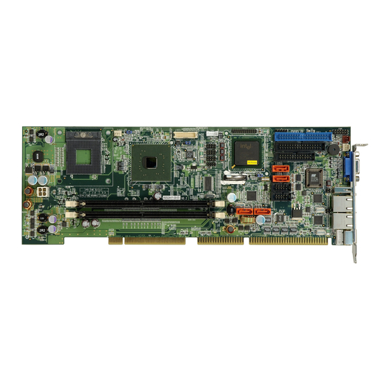
1.1 Introduction Figure 1-1: WSB-9152 The WSB-9152 PICMG 1.0 CPU card is a Socket 479 card for Intel® Pentium® M and Intel® Celeron® M processors. The WSB-9152 has a maximum front side bus (FSB) frequency of 533 MHz and can support two dual channel DDR2 memory modules of up to 1 GB each. -
Page 23: Wsb-9152 Benefits
None WSB-9152SDVI-R21 Table 1-1: WSB-9152 Model Variations 1.1.2 WSB-9152 Benefits Some of the WSB-9152 benefits are listed below: Intel® Pentium® M and Celeron® M mobile processors reduce power consumption Multiple display options with VGA, LVDS and DVI (on DVI models) -
Page 24: Wsb-9152 Overview
1.2.1 WSB-9152 Overview Photo The WSB-9152 has a wide variety of internal and external peripheral connectors. A labeled photo of the peripheral connectors on the front of the WSB-9152 is shown in Figure 1-2. Figure 1-2: WSB-9152 Overview [Front View] 1.2.2 WSB-9152 Peripheral Connectors and Jumpers... -
Page 25: Technical Specifications
The WSB-9152 has the following on-board jumpers: Clear CMOS FSB frequency selector LVDS voltage selector 1.2.3 Technical Specifications WSB-9152 technical specifications are listed in Table 1-2. See Chapter 2 for details. Specification WSB-9152 Form Factor PICMG 1.0 Intel® Pentium® M System CPU Intel®... - Page 26 WSB-9152 PICMG 1.0 SBC Specification WSB-9152 Northbridge: Intel® 915GME System Chipset Southbridge: Intel® ICH6-M Two 240-pin DIMM sockets support two dual channel Memory 400 MHz or 500 MHz DDR2 DIMMS with a maximum capacity of 1 GB each VGA: Integrated in the Intel® 915GME...
-
Page 27: Table 1-2: Technical Specifications
WSB-9152 PICMG 1.0 SBC Specification WSB-9152 5.1 Channel AC’97 audio kit with Realtek ALC655 codec Optional Audio 7.1 Channel HD audio kit with Realtek ALC883 and dual audio Interface support Table 1-2: Technical Specifications Page 7... -
Page 28: Detailed Specifications
WSB-9152 PICMG 1.0 SBC Chapter Detailed Specifications Page 8... -
Page 29: Overview
WSB-9152 PICMG 1.0 SBC 2.1 Overview This chapter describes the specifications and on-board features of the WSB-9152 in detail. 2.2 Dimensions 2.2.1 Board Dimensions The dimensions of the board are listed below: Length: 338.58 mm Width: 121.92 mm Figure 2-1: WSB-9152 Dimensions (mm) -
Page 30: External Interface Panel Dimensions
WSB-9152 PICMG 1.0 SBC 2.2.2 External Interface Panel Dimensions External peripheral interface connector panel dimensions are shown in Figure 2-2. Figure 2-2: External Interface Panel Dimensions (mm) Page 10... -
Page 31: Data Flow
WSB-9152 PICMG 1.0 SBC 2.3 Data Flow Figure 2-3 shows the data flow between the two on-board chipsets and other components installed on the motherboard and described in the following sections of this chapter. Figure 2-3: Data Flow Block Diagram... -
Page 32: Compatible Processors
WSB-9152 PICMG 1.0 SBC 2.4 Compatible Processors 2.4.1 Compatible Processor Overview Figure 2-4: Socket 479 The WSB-9152 supports the following socket 479 processors: Intel® Pentium® M processors Intel® Celeron® M processors All the above processors communicate with the Intel® 915GME Northbridge chipset through a 533 MHz or 400 MHz front side bus (FSB). -
Page 33: Intel 915Gme Northbridge Chipset
WSB-9152 PICMG 1.0 SBC Family CPU Speed Processor # Bus Speed Mfg Tech Cache Size 1.60 GHz 533 MHz 90 nm 2 MB L2 1.60 GHz 400 MHz 90 nm 2 MB L2 1.50 GHz 400 MHz 90 nm 2 MB L2 1.50 GHz... -
Page 34: Intel ® 915Gme Memory Support
® 2.5.1 Intel 915GME Memory Support WARNING: Only DDR2 memory modules can be installed on the WSB-9152. Do not install DDR memory modules. If a DDR module is installed on the WSB-9152, the WSB-9152 may be irreparably damaged. ® The Intel... -
Page 35: Intel ® 915Gme Integrated Graphics
WSB-9152 PICMG 1.0 SBC Figure 2-6: 240-pin DDR2 DIMM Socket ® 2.5.2 Intel 915GME Integrated Graphics The Intel® 915GME Northbridge chipset has an integrated graphics engine that supports the following display devices: Analog CRT Digital LVDS ® 2.5.2.1 Intel 915GME Analog CRT Support A DB-15 VGA connector on the external peripheral interface connector panel is interfaced ®... -
Page 36: Intel 915Gme Lvds Support
WSB-9152 PICMG 1.0 SBC ® 2.5.2.2 Intel 915GME LVDS Support A 30-pin LVDS crimp connector is interfaced to the Intel® 915GME graphics engine. Figure 2-7: LVDS Connector The Intel® 915GME internal graphics engine supports LVDS displays with the following features:... -
Page 37: Chrontel 7307C
WSB-9152 PICMG 1.0 SBC Spatial Dithering support to emulate up to 16 million colors for 18bpp TFT panels Spread spectrum clocking (SSC) supported Supports down and center SSC via an SSC clock from an external SSC clock chip. Supports down spread of – 2.5% or center spread of ± -1.25% in... -
Page 38: Intel ® 915Gme Direct Media Interface (Dmi)
WSB-9152 PICMG 1.0 SBC Supports Intel SDVO technology DVI 1.0 compliant Supports full operating range of Intel’s SDVO input port ® 2.5.3 Intel 915GME Direct Media Interface (DMI) ® Intel® 915GME Northbridge GMCH is connected to the Intel ICH6M Southbridge Chipset ®... -
Page 39: Intel ® Ich6M Azalia And Ac '97 Controllers
Integrated SATA host controller with DMA operations interfaced to two SATA connectors on the WSB-9152 Integrated IDE controller supports Ultra ATA 100/66/33 Supports the seven USB 2.0 devices on the WSB-9152 with four UHCI controllers and one EHCI controller Complies with System Management Bus (SMBus) Specification, Version 2.0 Supports Azalia and AC’97... -
Page 40: Intel ® Ich6M Ide Interface
WSB-9152 PICMG 1.0 SBC The Azalia and AC’97 audio controllers are integrated into the ICH6M. The Azalia controller complies with the Intel High Definition Audio Specification. The AC’97 controller complies with the AC’97 Specification, Version 2.3. Both the Azalia and AC’97 controllers are connected to the onboard audio connector. -
Page 41: Intel ® Ich6M Low Pin Count (Lpc) Interface
WSB-9152 PICMG 1.0 SBC Ultra ATA/100 Ultra ATA/66 Ultra ATA/33 Specification IDE devices PIO Mode 0 – 4 0 – 4 0 – 4 PIO Max Transfer Rate 16.6 MB/s 16.6 MB/s 16.6 MB/s DMA/UDMA designation UDMA 5 UDMA 4... -
Page 42: Pcie Gbe
WSB-9152 PICMG 1.0 SBC PCI Revision 2.3 compliant 33 MHz 5 V tolerant PCI signals (except PME#) Integrated PCI arbiter supports up to seven PCI bus masters The PCI bus is connected to an interface gold finger on the bottom of the CPU card and supports four expansion PCI cards on the backplane. -
Page 43: Intel ® Ich6M Real Time Clock
WSB-9152 PICMG 1.0 SBC Auto-Negotiation with Next Page capability Supports PCI rev.2.2, 32-bit, 33/66 MHz Supports pair swap/polarity/skew correction Crossover Detection & Auto-Correction Wake-on-LAN and remote wake-up support Microsoft® NDIS5 Checksum Offload (IP, TCP, UDP) and largesend offload support Supports Full Duplex flow control (IEEE 802.3x) Fully compliant with IEEE 802.3, IEEE 802.3u, IEEE 802.3ab... -
Page 44: Intel ® Ich6M Sata Controller
® 2.6.6 Intel ICH6M SATA Controller The integrated SATA controller on the ICH6M Southbridge supports two SATA drives on the WSB-9152 with independent DMA operations. Figure 2-14: SATA Ports SATA controller specifications are listed below. Supports two SATA drives Supports 1.5 Gb/s data transfer speeds Supports Serial ATA Specification, Revision 1.0a... -
Page 45: Jmicron Jmb363 Sata Ii Controller
Up to seven high-speed, full-speed or low-speed USB devices are supported by the ICH6M on the WSB-9152. High-speed USB 2.0, with data transfers of up to 480 MB/s, is enabled with the ICH6M integrated Enhanced Host Controller Interface (EHCI) compliant host controller. -
Page 46: Lpc Bus Components
WSB-9152 PICMG 1.0 SBC One of the Intel® ICH6M USB ports is implemented on the WSB-9152. Six more are available through headers on the WSB-9152. See Figure 2-16. Figure 2-16: Onboard USB Implementation 2.7 LPC Bus Components The LPC bus is connected to components listed below:... -
Page 47: Super I/O Chipset
WSB-9152 PICMG 1.0 SBC Figure 2-17: BIOS Chipset 2.7.2 Super I/O Chipset The Winbond W83627EHG Super I/O chipset is connected to the ICH6-M Southbridge through the LPC bus. The Winbond W83627EHG is an LPC interface-based Super I/O device that comes with Environment Controller integration. -
Page 48: Super I/O Lpc Interface
WSB-9152 PICMG 1.0 SBC Smart Fan control system, supports SMART FANTM I with “Thermal cruise™” and “Speed Cruise™” modes, and SMART FANTM III. One IEEE 1284 Parallel Port Floppy Disk Controller Keyboard Controller Watchdog Timer Serial IRQ Support Some of the Super I/O features are described in more detail below: 2.7.2.1 Super I/O LPC Interface... -
Page 49: Super I/O Parallel Port (Lpt)
WSB-9152 PICMG 1.0 SBC 16-byte data FIFOs Overrun and under run conditions detected Built-in address mark detection circuitry to simplify the read electronics FDD anti-virus functions with software write protect and FDD write enable signal Supports 3.5-inch or 5.25-inch FDD... -
Page 50: Super I/O Keyboard And Mouse Controller
Three thermal inputs on the WSB-9152 Super I/O Enhanced Hardware Monitor monitor the following temperatures: System temperature Power temperature CPU temperature Ten voltage inputs on the WSB-9152 Super I/O Enhanced Hardware Monitor monitor the following voltages: +1.5 V +1.8 V +3.3 V +5.0 V... -
Page 51: Operating Temperature And Temperature Control
Northbridge and Southbridge chipsets to ensure the operating temperature of these chips remain low. 2.8.3 Power Consumption Table 2-3 shows the power consumption parameters for the WSB-9152 running with an Intel® Pentium® M 2.0GHz/533 MHz processor and 512 MB PC3200 DDR2 SDRAM. Voltage... -
Page 52: Iei Expansion Pci/Px Backplanes
WSB-9152 PICMG 1.0 SBC 2.9.1 IEI Expansion PCI/PX Backplanes The backplanes listed in Table 2-4 are compatible with the WSB-9152 and can be used to develop highly integrated industrial applications. All of the backplanes listed below have 24-pin ATX connector and a 4-pin ATX connector. For more information about these backplanes please consult the IEI catalog or contact your vendor, reseller or the IEI sales team at sales@iei.com.tw. -
Page 53: Iei Chassis
Table 2-4: Compatible IEI PICOe Backplanes 2.9.2 IEI Chassis IEI chassis available for WSB-9152 system development are listed in Table 2-5. For more information about these chassis please consult the IEI catalog or contact your vendor, reseller or the IEI sales team at sales@iei.com.tw. -
Page 54: Table 2-5: Compatible Iei Chassis
WSB-9152 PICMG 1.0 SBC Model Slot SBC Mounting Max Slots Backplanes RACK-500G-R20 Full-size Rack PCI-5S2 A-R10 PCI-5S2 A-R30 RACK-814G-R20 Rack PCI-12S-RS-R30 PCI-13SD-RS-R30 PCI-14S-RS-R30 PCI-14S2-RS-R31 PCI-14S3-RS-R30 PX-14S2-RS-R30 PX-14S5-RS-R30 RACK-900G Full-size Rack PCI-10S-RS-R30 PCI-10S2-RS-R30 RACK-1150G Rack PCI-2SD2-RS-R30 RACK-1151G Rack PCI-2SD2-RS-R30 RACK-2000G Rack... -
Page 55: Unpacking
WSB-9152 PICMG 1.0 SBC Chapter Unpacking Page 35... -
Page 56: Anti-Static Precautions
When the WSB-9152 is unpacked, please do the following: Follow the anti-static precautions outlined in Section 3.1. Make sure the packing box is facing upwards so the WSB-9152 does not fall out of the box. Make sure all the components shown in Section 3.3 are present. -
Page 57: Unpacking Checklist
If some of the components listed in the checklist below are missing, please do not proceed with the installation. Contact the IEI reseller or vendor you purchased the WSB-9152 from or contact an IEI sales representative directly. To contact an IEI sales representative, please send an email to sales@iei.com.tw. -
Page 58: Table 3-1: Package List Contents
WSB-9152 PICMG 1.0 SBC Quantity Item and Part Number Image IO-KIT (DVI models (P/N:IO-KIT-001-R20 V2.0) only) KB/MS PS/2 Y-cable (P/N: 32000-000138-RS) Mini jumper pack Quick installation guide SATA cable (P/N: 32000-062800-RS) SATA power cable (P/N: 32100-088600-RS) Utility CD Table 3-1: Package List Contents... -
Page 59: Optional Items
The items listed in this section are optional items that must be ordered separately. Please contact your WSB-9152 vendor, distributor or reseller for more information or, contact iEi directly by sending an email to sales@iei.com.tw. The following optional items are available for the WSB-9152. Quantity Item and Part Number Image Audio kit_ 5.1 Channel... -
Page 60: Connector Pinouts
WSB-9152 PICMG 1.0 SBC Chapter Connector Pinouts Page 40... -
Page 61: Peripheral Interface Connectors
Figure 4-1 shows the on-board peripheral connectors, rear panel peripheral connectors and on-board jumpers. Figure 4-1: Connector and Jumper Locations 4.1.1 Peripheral Interface Connectors Table 4-1 shows a list of the peripheral interface connectors on the WSB-9152. Detailed descriptions of these connectors can be found below. Connector Type... -
Page 62: External Interface Panel Connectors
8-pin header USB45 Table 4-1: Peripheral Interface Connectors 4.1.2 External Interface Panel Connectors Table 4-2 lists the rear panel connectors on the WSB-9152. Detailed descriptions of these connectors can be found in Section 4.3 on page 67 Connector Type Label... -
Page 63: Internal Peripheral Connectors
Internal peripheral connectors are found on the motherboard and are only accessible when the motherboard is outside of the chassis. This section has complete descriptions of all the internal, peripheral connectors on the WSB-9152. 4.2.1 Audio Connector (9-pin) CN Label:... -
Page 64: Backlight Inverter Connector
5-pin wafer (1x5) CN Location: See Figure 4-3 CN Pinouts: See Table 4-4 The backlight inverter connector provides the backlight on the LCD display connected to the WSB-9152 with +12 V of power. Figure 4-3: Panel Backlight Connector Pinout Locations Page 44... -
Page 65: Backplane To Mainboard Connector
WSB-9152 PICMG 1.0 SBC PIN NO. DESCRIPTION LCD_BKLCTL GROUND 12 V GROUND ENABKL Table 4-4: Panel Backlight Connector Pinouts 4.2.3 Backplane to Mainboard Connector CN Label: ATXCTL1 3-pin wafer (1x3) CN Type: CN Location: See Figure 4-4 CN Pinouts: See Table 4-5 The backplane to mainboard connector closes the circuit between the mainboard and the backplane in which it is installed. -
Page 66: Fan Connector (+12 V, 4-Pin)
WSB-9152 PICMG 1.0 SBC Figure 4-4: Backplane to Mainboard Connector Location PIN NO. DESCRIPTION PS_ON# 5 VSB Table 4-5: Backplane to Mainboard Connector Pinouts 4.2.4 Fan Connector (+12 V, 4-pin) CN Label: CPU_FAN1 CN Type: 4-pin header CN Location: See Figure 4-5... -
Page 67: Cpu Power Connector
WSB-9152 PICMG 1.0 SBC The cooling fan connector provides a 12 V, 500mA current to a CPU cooling fan. The connector has a "rotation" pin to get rotation signals from fans and notify the system so the system BIOS can recognize the fan speed. Please note that only specified fans can issue the rotation signals. -
Page 68: Digital Input/Output (Dio) Connector
WSB-9152 PICMG 1.0 SBC CN Pinouts: See Table 4-7 The 4-pin ATX power connector is connected to an ATX power supply. Figure 4-6: ATX Power Connector Location PIN NO. DESCRIPTION GROUND GROUND +12 V +12 V Table 4-7: ATX Power Connector Pinouts 4.2.6 Digital Input/Output (DIO) Connector... -
Page 69: Figure 4-7: Dio Connector Locations
WSB-9152 PICMG 1.0 SBC CN Pinouts: See Table 4-8 The digital input/output connector is managed through a Super I/O chip. The DIO connector pins are user programmable. Figure 4-7: DIO Connector Locations PIN NO. DESCRIPTION PIN NO. DESCRIPTION Output 3... -
Page 70: Digital Video Interface (Dvi) Connector
WSB-9152 PICMG 1.0 SBC 4.2.7 Digital Video Interface (DVI) Connector CN Label: DVI1 26-pin header CN Type: CN Location: See Figure 4-8 CN Pinouts: See Table 4-9 The digital video interface connector is a digital visual interface for a digital display. The IO-KIT-001 is included with the WSB-9152DVI and WSB-9152SDVI. -
Page 71: Floppy Disk Connector (34-Pin)
WSB-9152 PICMG 1.0 SBC PIN NO DESCRIPTION PIN NO DESCRIPTION Data0- Data 0+ DDC Clock DDC Data Data 1- Data 1+ Clock+ Clock- Table 4-9: DVI Connector Pinouts 4.2.8 Floppy Disk Connector (34-pin) CN Label: FDD1 CN Type: 34-pin header (2x17) -
Page 72: Figure 4-9: 34-Pin Fdd Connector Location
WSB-9152 PICMG 1.0 SBC Figure 4-9: 34-pin FDD Connector Location PIN NO. DESCRIPTION PIN NO. DESCRIPTION REDUCE WRITE INDEX# MOTOR ENABLE A# DRIVE SELECT B# DRIVE SELECT A# MOTOR ENABLE B# DIRECTION# STEP# WRITE DATA# WRITE GATE# TRACK 0# Page 52... -
Page 73: Front Panel Connector (14-Pin)
WSB-9152 PICMG 1.0 SBC PIN NO. DESCRIPTION PIN NO. DESCRIPTION WRITE PROTECT# READ DATA# SIDE 1 SELECT# DISK CHANGE# Table 4-10: 34-pin FDD Connector Pinouts 4.2.9 Front Panel Connector (14-pin) CN Label: F_PANEL1 CN Type: 14-pin header (2x6) CN Location:... -
Page 74: Ide Connector (40-Pin)
WSB-9152 PICMG 1.0 SBC Figure 4-10: Front Panel Connector Pinout Locations FUNCTION DESCRIPTION FUNCTION DESCRIPTION Power LED +5 V Speaker +5 V Ground Power Button PWRBTN- Speaker Reset HDD LED +5 V Reset- HDD LED- Table 4-11: Front Panel Connector Pinouts 4.2.10 IDE Connector (40-pin) -
Page 75: Figure 4-11: Ide Device Connector Locations
WSB-9152 PICMG 1.0 SBC CN Location: See Figure 4-11 CN Pinouts: See Table 4-12 One 40-pin IDE device connector supports connectivity to two hard disk drives. Figure 4-11: IDE Device Connector Locations PIN NO. DESCRIPTION PIN NO. DESCRIPTION RESET# GROUND... -
Page 76: Keyboard Connector
WSB-9152 PICMG 1.0 SBC PIN NO. DESCRIPTION PIN NO. DESCRIPTION IDE CHRDY GROUND IDE DACK GROUND–DEFAULT INTERRUPT HDC CS0# HDC CS1# HDD ACTIVE# GROUND Table 4-12: IDE Connector Pinouts 4.2.11 Keyboard Connector CN Label: CN Type: 5-pin header (1x5) CN Location:... -
Page 77: Lvds Lcd Connector
WSB-9152 PICMG 1.0 SBC Figure 4-12: Keyboard Connector Location PIN NO. DESCRIPTION KEYBOARD CLOCK KEYBOARD DATA GROUND Table 4-13: Keyboard Connector Pinouts 4.2.12 LVDS LCD Connector CN Label: LVDS1 CN Type: 30-pin crimp (2x10) See Figure 4-13 CN Location: See Table 4-14... -
Page 78: Figure 4-13: Lvds Lcd Connector Pinout Locations
WSB-9152 PICMG 1.0 SBC The 30-pin LVDS LCD connector can be connected to single channel or dual channel, 18-bit or 36-bit LVDS panel. Figure 4-13: LVDS LCD Connector Pinout Locations PIN NO. DESCRIPTION PIN NO. DESCRIPTION GROUND GROUND LVDSA_Y0+ LVDSA_Y0-... -
Page 79: Parallel Port Connector
WSB-9152 PICMG 1.0 SBC PIN NO. DESCRIPTION PIN NO. DESCRIPTION LVDSB_Y1+ LVDSB_Y1- LVDSB_Y2+ LVDSB_Y2- LVDSB_CLK+ LVDSB_CLK- GROUND GROUND VCC_LVDS VCC_LVDS VCC_LVDS VCC_LVDS Table 4-14: LVDS LCD Port Connector Pinouts 4.2.13 Parallel Port Connector CN Label: LPT1 CN Type: 26-pin box header... -
Page 80: Figure 4-14: Parallel Port Connector Location
WSB-9152 PICMG 1.0 SBC Figure 4-14: Parallel Port Connector Location PIN NO. DESCRIPTION PIN NO. DESCRIPTION STROBE# DATA 0 DATA 1 DATA 2 DATA 3 DATA 4 DATA 5 DATA 6 DATA 7 ACKNOWLEDGE BUSY PAPER EMPTY PRINTER SELECT AUTO FORM FEED #... -
Page 81: Pcie Mini Card Connector
CN Pinouts: See Table 4-16 The PCIe Mini Card connector allows a PCIe Mini Card to be connected to the WSB-9152. PCIe Mini Cards are functionally identical to a PCI card in traditional desktop computers. They are used to add communications functions to computers that are built- or customized-to-order. -
Page 82: Figure 4-15: Pci Slot Location
WSB-9152 PICMG 1.0 SBC Figure 4-15: PCI Slot Location PIN NO. DESCRIPTION PIN NO. DESCRIPTION WAKE# 3.3 V_1 RESERVED_1 GND0 RESERVED_2 1.5 V_1 CLKREQ# UIM_PWR GND1 UIM_DATA REFCLK- UIM_CLOCK REFCLK+ UIM_RESET GND2 UIM_VPP UIM_C8 GND3 UIM_C4 W_DISABLE# GND4 PERST# PERn0 3.3 VAUX1... -
Page 83: Sata Drive Connectors
WSB-9152 PICMG 1.0 SBC PIN NO. DESCRIPTION PIN NO. DESCRIPTION PERp0 GND5 GND6 1.5 V_2 GND7 SMB_CLK PETn0 SMB_DATA PETp0 GND8 GND9 USB_D- RESERVED_3 USB_D+ RESERVED_4 GND10 RESERVED_5 LED_WWAN# RESERVED_6 LED_WLAN# RESERVED_7 LED_WPAN# RESERVED_8 1.5 V_3 RESERVED_9 GND11 RESERVED_10 3.3 V_2 Table 4-16: PCIe Mini Card Connector 4.2.15 SATA Drive Connectors... -
Page 84: Serial Port Connector (Com 2)
WSB-9152 PICMG 1.0 SBC Figure 4-16: SATA Drive Connector Locations PIN NO. DESCRIPTION Table 4-17: SATA Drive Connector Pinouts 4.2.16 Serial Port Connector (COM 2) CN Label: COM1 and COM2 10-pin header (2x5) CN Type: CN Location: See Figure 4-17... -
Page 85: Figure 4-17: Com Connector Pinout Locations
WSB-9152 PICMG 1.0 SBC CN Pinouts: See Table 4-18 The 10-pin serial port connectors provide a further two RS-232 serial communications channels. The serial port connectors can be connected to external RS-232 serial port devices. Figure 4-17: COM Connector Pinout Locations PIN NO. -
Page 86: Usb Connectors (Internal)
WSB-9152 PICMG 1.0 SBC 4.2.17 USB Connectors (Internal) CN Label: USB01, USB23 and USB45 8-pin header (2x4) CN Type: CN Location: See Figure 4-18 CN Pinouts: See Table 4-19 The 2x4 USB pin connectors each provide connectivity to two USB 1.1 or two USB 2.0 ports. -
Page 87: External Peripheral Interface Connector Panel
Table 4-19: USB Port Connector Pinouts 4.3 External Peripheral Interface Connector Panel Figure 4-19 shows the WSB-9152 rear panel. The WSB-9152 rear panel consists of two RJ-45 Ethernet connectors, a PS/2 keyboard connector a USB port and a VGA connector. -
Page 88: Lan Connectors
CN Pinouts: See Table 4-21 The WSB-9152 is equipped with two built-in PCI3 GbE Ethernet controllers. The controllers can connect to the LAN through two RJ-45 LAN connectors. There are two LEDs on the connector indicating the status of LAN. The pin assignments are listed in the... -
Page 89: Usb Connector
CN Type: USB port CN Location: See Figure 4-19 CN Pinouts: See Table 4-23 The WSB-9152 has a one external USB 2.0 port. The port connects to both USB 2.0 and USB 1.1 devices. PIN NO. DESCRIPTION DATA- DATA+ Page 69... -
Page 90: Vga Connector
VGA1 CN Type: 15-pin Female CN Location: See Figure 4-19 CN Pinouts: See Figure 4-22 and Table 4-24 The WSB-9152 has a single 15-pin female connector for connectivity to standard display devices. Figure 4-22: VGA Connector DESCRIPTION DESCRIPTION GREEN BLUE... -
Page 91: Installation
WSB-9152 PICMG 1.0 SBC Chapter Installation Page 71... -
Page 92: Anti-Static Precautions
Electrostatic discharge (ESD) can cause serious damage to electronic components, including the WSB-9152. Dry climates are especially susceptible to ESD. It is therefore critical that whenever the WSB-9152, or any other electrical component is handled, the following anti-static precautions are strictly adhered to. -
Page 93: Installation Notices
This helps to prevent potential ESD damage. Turn all power to the WSB-9152 off: When working with the WSB-9152, make sure that it is disconnected from all power supplies and that no electricity is being fed into the system. -
Page 94: Cpu, Cpu Cooling Kit And Dimm Installation
Running a CPU without a cooling kit may also result in injury to the user. The CPU, CPU cooling kit and DIMM are the most critical components of the WSB-9152. If one of these component is not installed the WSB-9152 cannot run. -
Page 95: Socket 479 Cpu Installation
WSB-9152 PICMG 1.0 SBC 5.3.1 Socket 479 CPU Installation To install a socket 479 CPU onto the WSB-9152, follow the steps below: WARNING: CPUs are expensive and sensitive components. When installing the CPU please be careful not to damage it in anyway. Make sure the CPU is installed properly and ensure the correct cooling kit is properly installed. -
Page 96: Figure 5-2: Lock The Cpu Socket Retention Screw
WSB-9152 PICMG 1.0 SBC Step 2: Inspect the CPU socket. Make sure there are no bent pins and make sure the socket contacts are free of foreign material. If any debris is found, remove it with compressed air. Step 3: Correctly Orientate the CPU. -
Page 97: Cooling Kit Cf-479B-Rs Installation
WSB-9152 PICMG 1.0 SBC 5.3.2 Cooling Kit CF-479B-RS Installation Figure 5-3: IEI CF-479B-RS Cooling Kit An IEI Socket 479 CPU cooling kit can be purchased separately. The cooling kit comprises a CPU heat sink and a cooling fan. WARNING: Do not wipe off (accidentally or otherwise) the pre-sprayed layer of thermal paste on the bottom of the CF-479B-RS heat sink. -
Page 98: Figure 5-4: Cooling Kit Support Bracket
WSB-9152 PICMG 1.0 SBC Figure 5-4: Cooling Kit Support Bracket Step 4: Tighten the screws. Use a screwdriver to tighten the four screws. Tighten each nut a few turns at a time and do not over-tighten the screws. Step 5: Connect the fan cable. -
Page 99: Dimm Installation
5.3.3 DIMM Installation WARNING: Using incorrectly specified DIMM may cause permanently damage the WSB-9152. Please make sure the purchased DIMM complies with the memory specifications of the WSB-9152. DIMM specifications compliant with the WSB-9152 are listed in Chapter 2. To install a DIMM into a DIMM socket, please follow the steps below and refer to Figure 5-6. -
Page 100: Jumper Settings
Before the WSB-9152 is installed in the system, the jumpers must be set in accordance with the desired configuration. The jumpers on the WSB-9152 are listed in Table 5-1 and shown in Figure 5-7. -
Page 101: Clear Cmos Jumper
Jumper Location: See Figure 5-8 If the WSB-9152 fails to boot due to improper BIOS settings, the clear CMOS jumper clears the CMOS data and resets the system BIOS information. To do this, use the jumper cap to close pins 2 and 3 for a few seconds then reinstall the jumper clip back to pins 1 and 2. -
Page 102: Cpu Frequency Selection Jumper
Jumper Type: Jumper Settings: See Table 5-3 Jumper Location: See Figure 5-9 The CPU frequency selection jumper enables a user to select the FSB speed on the WSB-9152. The CPU frequency selection jumper settings are shown in Table 5-3. Page 82... -
Page 103: Lvds Panel Resolution Jumper
WSB-9152 PICMG 1.0 SBC Pin Settings Description Short 1 – 2 400 MHz Short 2 – 3 533 MHz Default Table 5-3: CPU Frequency Selection Settings The location of the FSB Setup jumper is shown in Figure 5-9 below. Figure 5-9: CPU Frequency Selection Jumper 5.4.3 LVDS Panel Resolution Jumper... -
Page 104: Lvds Voltage Selection
Figure 5-10: LVDS Panel Resolution Jumper 5.4.4 LVDS Voltage Selection WARNING: Permanent damage to the screen and WSB-9152 may occur if the wrong voltage is selected with this jumper. Please refer to the user guide that cam with the monitor to select the correct voltage. -
Page 105: Figure 5-11: Lvds Voltage Selection Jumper Location
WSB-9152 PICMG 1.0 SBC Jumper Label: J_VLVDS1 Jumper Type: 3-pin header Jumper Settings: See Table 5-5 Jumper Location: See Figure 5-11 The LVDS Voltage Selection jumper allows the LVDS screen voltage to be set. The LVDS Voltage Selection jumper settings are shown in Table 5-5. -
Page 106: Chassis Installation
The WSB-9152 must be installed in a chassis with ventilation holes on the sides allowing airflow to travel through the heat sink surface. In a system with an individual power supply unit, the cooling fan of a power supply can also help generate airflow through the board surface. -
Page 107: Cpu Card Installation
5.5.3 CPU Card Installation To install the WSB-9152 CPU card onto the backplane, carefully align the CPU card interface connectors with the corresponding socket on the backplane. To do this, please refer to the reference material that came with the backplane. Next, secure the CPU card to the chassis. -
Page 108: Ide Cable Connection
7.1 channel audio kit 5.1 channel audio kit 5.6.2 IDE Cable Connection The IDE flat cable connects the WSB-9152 to one or two IDE devices. To connect an IDE HDD to the WSB-9152 please follow the instructions below. Step 1: Locate the IDE connector. -
Page 109: Channel Audio Kit Installation
The optional 5.1 channel audio kit connects to the 10-pin audio connector on the WSB-9152. The audio kit consists of three audio jacks. One audio jack, Mic In, connects to a microphone. The remaining two audio jacks, Line-In and Line-Out, connect to two speakers. -
Page 110: Channel Audio Kit Installation
Send any queries to sales@iei.com.tw. The optional 7.1 channel audio kit connects to the 10-pin audio connector on the WSB-9152. The audio kit consists of five audio jacks. One audio jack, Mic In, connects to Page 90... -
Page 111: Figure 5-14: 7.1 Channel Audio Kit
Connect the audio kit cable. The audio kit is shipped with a cable that connects the audio kit to the WSB-9152. Connect the cable to the connector on the back of the audio kit. Make sure the pins are properly aligned (i.e. pin 1 connects to pin 1). -
Page 112: Fdd Cable Connection
Refer to Chapter 7 for driver installation instructions.Step 0: 5.6.5 FDD Cable Connection The FDD flat cable connects to the WSB-9152 to one FDD device. To connect an FDD to the WSB-9152 please follow the instructions below. Step 1: Locate the FDD connector. -
Page 113: Parallel Port Cable
Step 3: Insert the cable connectors. Once the cable connector is properly aligned with the 26-pin box-header connector on the WSB-9152, connect the cable connector to the onboard connector. See Figure 5-16. Figure 5-16: LPT Cable Connection Step 4: Attach the LPT connector bracket to the chassis. The LPT cable connector is connected to a standard external LPT interface connector. -
Page 114: Dual Rs-232 Cable Connection
WSB-9152 PICMG 1.0 SBC Step 5: Connect LPT device. Once the LPT interface connector is connected to the chassis, the LPT device can be connected to the LPT interface connector. See Figure 5-17Step 0:\ Figure 5-17: Connect the LPT Device 5.6.7 Dual RS-232 Cable Connection... -
Page 115: Sata Drive Connection
0: 5.6.8 SATA Drive Connection The WSB-9152 is shipped with two SATA drive cables and one SATA drive power cable. To connect the SATA drives to the connectors, please follow the steps below. Step 1: Locate the connectors. -
Page 116: Figure 5-19: Sata Drive Cable Connection
WSB-9152 PICMG 1.0 SBC Figure 5-19: SATA Drive Cable Connection Step 3: Connect the cable to the SATA disk. Connect the connector on the other end of the cable to the connector at the back of the SATA drive. See Figure 5-20. -
Page 117: Wafer-To-Ps/2 Cable (Keyboard/Mouse Installation)
WSB-9152 keyboard or mouse connector. See Figure 5-21. Step 3: Insert the cable connectors. Once the cable connector is properly aligned with the keyboard/mouse connector on the WSB-9152, connect the cable connector to the onboard connectors. See Figure 5-21. Page 97... -
Page 118: External Peripheral Interface Connection
WSB-9152 PICMG 1.0 SBC Figure 5-21: Keyboard/mouse Cable Connection Step 4: Attach PS/2 connector to the chassis. The wafer-to-PS/2 cable connector is connected to a PS/2 connector. To secure the PS/2 connector to the chassis please refer to the installation instructions that came with the chassis. -
Page 119: Lan Connection (Single Connector)
WSB-9152 PICMG 1.0 SBC To install these devices, connect the corresponding cable connector from the actual device to the corresponding WSB-9152 external peripheral interface connector making sure the pins are properly aligned. 5.7.1 LAN Connection (Single Connector) There are two external RJ-45 LAN connectors. The RJ-45 connectors enable connection to an external network. -
Page 120: Usb Device Connection
5.7.2 USB Device Connection There are two external USB 2.0 connectors. Both connectors are perpendicular to the WSB-9152. To connect a USB 2.0 or USB 1.1 device, please follow the instructions below. Step 1: Located the USB connectors. The locations of the USB connectors are shown in Chapter 4. -
Page 121: Figure 5-24: Vga Connector
WSB-9152 PICMG 1.0 SBC Step 1: Locate the female DB-15 connector. The location of the female DB-15 connector is shown in Chapter 3. Step 2: Align the VGA connector. Align the male DB-15 connector on the VGA screen cable with the female DB-15 connector on the external peripheral interface. -
Page 122: Ami Bios
WSB-9152 PICMG 1.0 SBC Chapter AMI BIOS Page 102... -
Page 123: Introduction
WSB-9152 PICMG 1.0 SBC 6.1 Introduction A licensed copy of AMI BIOS is preprogrammed into the ROM BIOS. The BIOS setup program allows users to modify the basic system configuration. This chapter describes how to access the BIOS setup program and the configuration options that may be changed. -
Page 124: Getting Help
WSB-9152 PICMG 1.0 SBC Function F1 key General help, only for Status Page Setup Menu and Option Page Setup Menu F2 /F3 key Change color from total 16 colors. F2 to select color forward. F10 key Save all the CMOS changes, only for Main Menu Table 6-1: BIOS Navigation Keys 6.1.3 Getting Help... -
Page 125: Main
WSB-9152 PICMG 1.0 SBC 6.2 Main The Main BIOS menu (BIOS Menu 1) appears when the BIOS Setup program is entered. The Main menu gives an overview of the basic system information. BIOS Menu 1: Main System Overview The System Overview lists a brief summary of different system components. The fields in System Overview cannot be changed. -
Page 126: Advanced
WSB-9152 PICMG 1.0 SBC Type: Names the currently installed processor Speed: Lists the processor speed Count: The number of CPUs on the motherboard System Memory: Displays the auto-detected system memory. Size: Lists memory size The System Overview field also has two user configurable fields: System Time [hh:mm:ss] Use the System Time option to set the system time. - Page 127 WSB-9152 PICMG 1.0 SBC BIOS Menu 2: Advanced Page 107...
-
Page 128: Cpu Configuration
WSB-9152 PICMG 1.0 SBC 6.3.1 CPU Configuration Use the CPU Configuration menu (BIOS Menu 3) to view detailed CPU specifications and configure the CPU. BIOS Menu 3: CPU Configuration The CPU Configuration menu (BIOS Menu 3) lists the following CPU details:... -
Page 129: Ide Configuration
WSB-9152 PICMG 1.0 SBC 6.3.2 IDE Configuration Use the IDE Configuration menu (BIOS Menu 4) to change and/or set the configuration of the IDE devices installed in the system. BIOS Menu 4: IDE Configuration ATA/IDE Configurations [Compatible] Disabled Disable all ATA/IDE ports. No Primary/Secondary IDE mode is presented for configuration. - Page 130 WSB-9152 PICMG 1.0 SBC Enhanced If this option is selected, “Configure SATA as” and “Configure SATA channels” options are presented for configuration. Legacy IDE Channels [PATA Pri, SATA Sec] Enables up to two SATA devices. SATA Only SATA Pri, PATA Sec...
-
Page 131: Ide Master, Ide Slave
WSB-9152 PICMG 1.0 SBC AHCI Enables the Advanced Host Controller Interface to allow use of NCQ and hot swapping. Please check operating system compatibility before switching to this mode. 6.3.2.1 IDE Master, IDE Slave Use the IDE Master and IDE Slave configuration menu (BIOS Menu 5) to view both primary and secondary IDE device details and configure the IDE devices connected to the system. - Page 132 WSB-9152 PICMG 1.0 SBC Auto-Detected Drive Parameters The “grayed-out” items in the left frame are IDE disk drive parameters automatically detected from the firmware of the selected IDE disk drive. The drive parameters are listed as follows: Device: Lists the device type (e.g. hard disk, CD-ROM etc.)
- Page 133 WSB-9152 PICMG 1.0 SBC CD/DVD The CD/DVD option specifies that an IDE CD-ROM drive is attached to the specified IDE channel. The BIOS does not attempt to search for other types of IDE disk drives on the specified channel. This option specifies an ATAPI Removable Media Device.
- Page 134 WSB-9152 PICMG 1.0 SBC PIO Mode [Auto] Use the PIO Mode option to select the IDE PIO (Programmable I/O) mode program timing cycles between the IDE drive and the programmable IDE controller. As the PIO mode increases, the cycle time decreases.
- Page 135 WSB-9152 PICMG 1.0 SBC MWDMA1 Multi Word DMA mode 1 selected with a maximum data transfer rate of 13.3 MB/s Multi Word DMA mode 2 selected with a maximum data MWDMA2 transfer rate of 16.6 MB/s UDMA1 Ultra DMA mode 0 selected with a maximum data transfer rate of 16.6 MB/s...
-
Page 136: Floppy Configuration
WSB-9152 PICMG 1.0 SBC Disabled Prevents the BIOS from using 32-bit data transfers. Allows BIOS to use 32-bit data transfers on supported Enabled EFAULT hard disk drives. 6.3.3 Floppy Configuration Use the Floppy Configuration menu (BIOS Menu 6) configures the floppy disk drive. -
Page 137: Super Io Configuration
WSB-9152 PICMG 1.0 SBC 1.2 MB 51/4” 720 KB 31/2” 1.44 MB 31/2’ D EFAULT 2.88 MB 31/2” 6.3.4 Super IO Configuration Use the Super IO Configuration menu (BIOS Menu 7) to set or change the configurations for the FDD controllers, parallel ports and serial ports. - Page 138 WSB-9152 PICMG 1.0 SBC 3F8/IRQ4 Serial Port 1 I/O port address is 3F8 and the interrupt EFAULT address is IRQ4 Serial Port 1 I/O port address is 3E8 and the interrupt 3E8/IRQ4 address is IRQ4 2E8/IRQ3 Serial Port 1 I/O port address is 2E8 and the interrupt...
- Page 139 WSB-9152 PICMG 1.0 SBC Parallel Port I/O port address is 278 Parallel Port I/O port address is 3BC Parallel Port Mode [Normal] Use the Parallel Port Mode option to select the mode the parallel port operates in. Normal The normal parallel port mode is the standard mode EFAULT for parallel port operation.
-
Page 140: Hardware Health Configuration
WSB-9152 PICMG 1.0 SBC 6.3.5 Hardware Health Configuration The Hardware Health Configuration menu (BIOS Menu 8) shows the operating temperature, fan speeds and system voltages. BIOS Menu 8: Hardware Health Configuration H/W Health Function The following system parameters and values are shown. The system parameters that are... -
Page 141: Remote Access Configuration
WSB-9152 PICMG 1.0 SBC System Fan Speed Voltages: The following system voltages are monitored +1.5 V +1.8 V +3.3 V +5 V +12 V VBAT SYSFAN Mode Setting [Manual Mode] Use the SYSFAN Mode Setting option to configure the system fan. - Page 142 WSB-9152 PICMG 1.0 SBC allows a remote host running a terminal program to display and configure the BIOS settings. BIOS Menu 9: Remote Access Configuration [Advanced] Remote Access [Disabled] Use the Remote Access option to enable or disable access to the remote functionalities of the system.
- Page 143 WSB-9152 PICMG 1.0 SBC Enabled Remote access configuration options shown below appear: Serial Port Number Serial Port Mode Flow Control Redirection after BIOS POST Terminal Type VT-UTF8 Combo Key Support These configuration options are discussed below. Serial Port Number [COM1] Use the Serial Port Number option selects the serial port used for remote access.
- Page 144 WSB-9152 PICMG 1.0 SBC NOTE: Identical baud rate setting musts be set on the host (a management computer running a terminal software) and the slave Redirection After BIOS POST [Always] Use the Redirection After BIOS POST option to specify when console redirection should occur.
-
Page 145: Usb Configuration
WSB-9152 PICMG 1.0 SBC 6.3.7 USB Configuration Use the USB Configuration menu (BIOS Menu 10) to read USB configuration information and configure the USB settings. BIOS Menu 10: USB Configuration USB Functions [Enabled] Use the USB Function BIOS option to enable or disable USB function support. - Page 146 WSB-9152 PICMG 1.0 SBC 8 USB Ports 8 USB ports enabled EFAULT USB 2.0 Controller [Enabled] Use the USB 2.0 Controller BIOS option to enable or disable the USB 2.0 controller USB 2.0 controller disabled Disabled Enabled USB 2.0 controller enabled...
-
Page 147: Pci/Pnp
WSB-9152 PICMG 1.0 SBC 6.4 PCI/PnP Use the PCI/PnP menu (BIOS Menu 11) to configure advanced PCI and PnP settings. WARNING: Setting wrong values for the BIOS selections in the PCIPnP BIOS menu may cause the system to malfunction. BIOS Menu 11: PCI/PnP Configuration... - Page 148 WSB-9152 PICMG 1.0 SBC Available The specified IRQ is available to be used by EFAULT PCI/PnP devices The specified IRQ is reserved for use by Legacy ISA Reserved devices Available IRQ addresses are: IRQ3 IRQ4 IRQ5 IRQ7 IRQ9 IRQ10 IRQ 11...
-
Page 149: Boot
WSB-9152 PICMG 1.0 SBC Reserved Memory Size [Disabled] Use the Reserved Memory Size BIOS option to specify the amount of memory that should be reserved for legacy ISA devices. Disabled No memory block reserved for legacy ISA devices EFAULT 16 KB reserved for legacy ISA devices... -
Page 150: Boot Settings Configuration
WSB-9152 PICMG 1.0 SBC 6.5.1 Boot Settings Configuration Use the Boot Settings Configuration menu (BIOS Menu 13) to configure advanced system boot options. BIOS Menu 13: Boot Settings Configuration Quick Boot [Enabled] Use the Quick Boot BIOS option to make the computer speed up the boot process. - Page 151 WSB-9152 PICMG 1.0 SBC Quiet Boot [Disabled] Use the Quiet Boot BIOS option to select the screen display when the system boots. Normal POST messages displayed Disabled EFAULT Enabled OEM Logo displayed instead of POST messages AddOn ROM Display Mode [Force BIOS] Use the AddOn ROM Display Mode option to allow add-on ROM (read-only memory) messages to be displayed.
-
Page 152: Boot Device Priority
WSB-9152 PICMG 1.0 SBC Disabled System cannot be booted from the LAN System can be booted from the LAN Enabled EFAULT Boot From SATA Support [Enabled] Use the Boot From SATA Support option to enable the system to be booted from a SATA device. -
Page 153: Hard Disk Drives
WSB-9152 PICMG 1.0 SBC BIOS Menu 14: Boot Device Priority Settings 6.5.3 Hard Disk Drives Use the Hard Disk Drives menu (BIOS Menu 15) to specify the boot sequence of the available HDDs. When the menu is opened, the HDDs connected to the system are listed... - Page 154 WSB-9152 PICMG 1.0 SBC NOTE: Only the drives connected to the system are shown. For example, if only two HDDs are connected only “1st Drive” and “2nd Drive” are listed. The boot sequence from the available devices is selected. If the “1st Drive” option is selected a list of available HDDs is shown.
-
Page 155: Removable Drives
WSB-9152 PICMG 1.0 SBC 6.5.4 Removable Drives Use the Removable Drives menu (BIOS Menu 16) to specify the boot sequence of the available FDDs. When the menu is opened, the FDDs connected to the system are listed as shown below:... -
Page 156: Cd/Dvd Drives
WSB-9152 PICMG 1.0 SBC BIOS Menu 16: Removable Drives 6.5.5 CD/DVD Drives Use the CD/DVD Drives menu (BIOS Menu 17) to specify the boot sequence of the available CD/DVD drives. When the menu is opened, the CD drives and DVD drives... - Page 157 WSB-9152 PICMG 1.0 SBC NOTE: Only the drives connected to the system are shown. For example, if only two CDs or DVDs are connected only “1st Drive” and “2nd Drive” are listed. The boot sequence from the available devices is selected. If the “1st Drive” option is selected a list of available CD/DVD drives is shown.
-
Page 158: Security
WSB-9152 PICMG 1.0 SBC 6.6 Security Use the Security menu (BIOS Menu 18) to set system and user passwords. BIOS Menu 18: Security Change Supervisor Password Use the Change Supervisor Password to set or change a supervisor password. The default for this option is Not Installed. If a supervisor password must be installed, select this field and enter the password. -
Page 159: Chipset
WSB-9152 PICMG 1.0 SBC password. After the password has been added, Install appears next to Change User Password. Clear User Password Use Clear User Password to clear the user password. 6.7 Chipset Use the Chipset menu (BIOS Menu 19) to access the Northbridge and Southbridge configuration menus. - Page 160 WSB-9152 PICMG 1.0 SBC BIOS Menu 19: Chipset Page 140...
-
Page 161: Northbridge Configuration
WSB-9152 PICMG 1.0 SBC 6.7.1 Northbridge Configuration Use the Northbridge Configuration menu (BIOS Menu 20) to configure the Northbridge chipset. BIOS Menu 20:Northbridge Chipset Configuration Memory Hole [Disabled] Use the Memory Hole option to reserve memory space between 15 MB and 16 MB for ISA expansion cards that require a specified area of memory to work properly. - Page 162 WSB-9152 PICMG 1.0 SBC 15 MB – 16 MB Between 15 MB and 16 MB of memory is reserved for ISA expansion cards Internal Graphics Mode Select [Enable, 8 MB] Use the Internal Graphic Mode Select option to specify the amount of system memory that can be used by the Internal graphics device.
-
Page 163: Southbridge Chipset Configuration
WSB-9152 PICMG 1.0 SBC 6.7.2 Southbridge Chipset Configuration The Southbridge Chipset Configuration menu (BIOS Menu 21) allows the Southbridge chipset to be configured. BIOS Menu 21:Southbridge Chipset Configuration Azalia/AC’97 Selection [Auto] Use the Azalia/AC’97 Selection option to choose the correct audio codec. -
Page 164: Power
WSB-9152 PICMG 1.0 SBC PCIe Ports Configuration Enable/Disable any of the following PCIe ports PCIe GbE Port 1 (can only be disabled if all other ports are disabled first) PCIe GbE Port 2 SATA ports Mini PCIe Port 6.8 Power The Power menu (BIOS Menu 22) allows the advanced power management options to be configured. -
Page 165: Advanced Power Configuration
WSB-9152 PICMG 1.0 SBC Power Supply Type [ATX] Use the Power Supply Mode BIOS option to select the power supply that is connected to the system. An AT power supply is connected to the system An ATX power supply is connected to the system EFAULT 6.8.1 Advanced Power Configuration... - Page 166 WSB-9152 PICMG 1.0 SBC Power Button Mode [On/Off] The Power Button mode BIOS specifies how the power button functions. When the power button is pressed the system is On/Off DEFAULT either turned on or off When the power button is pressed the system goes...
-
Page 167: Exit
WSB-9152 PICMG 1.0 SBC Disabled Wake event not generated by PCI PME controller EFAULT activity Wake event generated by PCI PME controller activity Enabled RI Resume [Disabled] The RI Resume BIOS option specifies if the system will be roused from a suspended or standby state when there is activity on the RI (ring in) modem line. - Page 168 WSB-9152 PICMG 1.0 SBC BIOS Menu 24:Exit Save Changes and Exit Use the Save Changes and Exit option to save the changes made to the BIOS options and to exit the BIOS configuration setup program. Discard Changes and Exit Use the Discard Changes and Exit option to exit the BIOS configuration setup program without saving the changes made to the system.
- Page 169 WSB-9152 PICMG 1.0 SBC Load Optimal Defaults Use the Load Optimal Defaults option to load the optimal default values for each of the parameters on the Setup menus. F9 key can be used for this operation. Load Failsafe Defaults Use the Load Failsafe Defaults option to load failsafe default values for each of the parameters on the Setup menus.
-
Page 170: Raid Setup
WSB-9152 PICMG 1.0 SBC Chapter RAID Setup Page 150... -
Page 171: Introduction
WSB-9152 PICMG 1.0 SBC 7.1 Introduction The JMicron JMB363 SATA RAID chipset can control parallel ATA (PATA) and SATA disks. The JMicron controller supports PATA UDMA transfer modes up to mode 6 and SATA II disk drives. The JMicron JMB363’s RAID functionality can increase the data read/write speed (RAID 0) or provide data protection by mirroring drive data (RAID 1). -
Page 172: Features And Benefits
WSB-9152 PICMG 1.0 SBC CAUTION! Do not accidentally disconnect the SATA drive cables. Carefully route the cables within the chassis to avoid system down time. 7.2 Features and Benefits Supports RAID levels 0, 1, and JBOD Supports connectivity to two disk drives... - Page 173 WSB-9152 PICMG 1.0 SBC Step 4: The following screen appears. Press Ctrl-J to enter the JMicron RAID BIOS. Figure A-1: Accessing JMicron RAID BIOS Utility Step 5: The main menu appears. The top left block gives menu options, the top right block lists your hard drives and the bottom block shows your RAID drives.
-
Page 174: Creating Araid Array
WSB-9152 PICMG 1.0 SBC 7.4 Creating a RAID Array To create a new RAID array, please follow the steps below: Step 1: Highlight the “Create RAID Disk Drive” menu option and press ENTER. Figure A-1: Select “Create RAID Disk Array”... - Page 175 WSB-9152 PICMG 1.0 SBC Step 4: Select the type of RAID array. RAID 0, RAID 1 and JBOD are supported. Refer to 7.11 for information on RAID levels. Use the up and down arrows to change, and press ENTER to continue.
- Page 176 WSB-9152 PICMG 1.0 SBC Step 6: Select the block size to be used on the new drive. If unsure, don’t change it. Press ENTER to continue. Figure A-5: Select Block Size Step 7: Choose the size of the new RAID array. By default the largest size possible is chosen.
-
Page 177: Deleting Araid Array
WSB-9152 PICMG 1.0 SBC Step 8: A confirmation block will appear. Type Y to create the new RAID array, or N to return to the main menu.Step 0: Figure A-7: Confirm RAID Creation 7.5 Deleting a RAID Array To delete a RAID array, please follow the steps below: Step 1: Highlight the “Delete RAID Disk Drive”... - Page 178 WSB-9152 PICMG 1.0 SBC Step 2: Highlight the RAID array to be deleted. Press SPACE to mark it for deletion. Press DEL to confirm deletion. Figure A-2: Choose RAID Array Step 3: Confirm deletion again. Remember that all data will be lost. Press Y to delete the array, or N to go back to the main menu.
-
Page 179: Revert A Hard Drive To Non-Raid
WSB-9152 PICMG 1.0 SBC 7.6 Revert a Hard Drive to Non-RAID If one hard drive comes from another RAID array and it’s been added to the system, this option will change it back into a non-RAID drive so it can be added to a new RAID array or used as a normal hard drive. -
Page 180: Solve Mirror Conflict
WSB-9152 PICMG 1.0 SBC Step 3: Confirm reversion to non-RAID. Remember that all data will be lost. Press Y to revert them, or N to go back to the main menu. Step 0: Figure A-3: Confirm Revert 7.7 Solve Mirror Conflict If both drives are the source for a RAID array the BIOS recognizes them as two separate drives. -
Page 181: Rebuild Mirror Drive
WSB-9152 PICMG 1.0 SBC Step 2: Select the source drive, and then the mirror drive can be rebuilt. The source drive is the working drive with your data. Step 0: Figure A-2: Rebuild Mirror Drive 7.8 Rebuild Mirror Drive If one of the two drives in a RAID 1 array has been replaced, the RAID drive can be rebuilt without loss of data. -
Page 182: Save And Exit Setup
WSB-9152 PICMG 1.0 SBC Step 2: Choose the RAID disk drive to rebuild. Press ENTER to start rebuilding. Figure A-2: Rebuild Mirror Drive Step 3: The status bar at the bottom of the screen shows rebuilding status.Step 0: Figure A-3: Rebuilding Mirror Drive 7.9 Save and Exit Setup... -
Page 183: Exit Without Saving
WSB-9152 PICMG 1.0 SBC Step 2: Press Y to save your changes and exit, or press N to go back to the Main Menu. Step 0: Figure A-2: Confirm Save and Exit 7.10 Exit Without Saving Exit the BIOS setup without saving your changes. Note that this will not undo changes to the RAID arrays. - Page 184 WSB-9152 PICMG 1.0 SBC Step 2: Press Y to exit the BIOS without saving your changes, or press N to go back to the main menu. Step 0: Figure A-2: Quit Without Saving (Y/N) Page 164...
-
Page 185: Raid Options
WSB-9152 PICMG 1.0 SBC 7.11 RAID Options The JMicron JMB363 RAID controller has offers RAID 0, RAID 1 and JBOD RAID solutions. 7.11.1 RAID 0 Striping – For Performance RAID 0 stripes logical data over both the disks in the RAID array. Blocks of data are alternately written to one disk and then the other. -
Page 186: Raid 1 Mirror - For Redundancy
WSB-9152 PICMG 1.0 SBC 7.11.2 RAID 1 Mirror – For Redundancy RAID 1 mirrors data over both disks RAID array. RAID 1 allows redundancy so data can be restored if one of the disks fails. There is a negligible performance difference between a RAID 1 array and a normal drive. -
Page 187: Driver Installation
WSB-9152 PICMG 1.0 SBC Chapter Driver Installation Page 167... -
Page 188: Available Software Drivers
LAN driver Installation instructions are given below. 8.2 Driver CD Auto-run All the drivers for the WSB-9152 are on the CD that came with the system. To install the drivers, please follow the steps below. Step 1: Insert the CD into a CD drive connected to the system. -
Page 189: Figure 8-1: Introduction Screen
WSB-9152 PICMG 1.0 SBC Figure 8-1: Introduction Screen Step 4: A new screen with a list of available drivers appears (Figure 8-2). Page 169... -
Page 190: Chipset Driver Installation
WSB-9152 PICMG 1.0 SBC Figure 8-2: Available Drivers Step 5: Select the driver to install from the list in Figure 8-2. Step 0: 8.3 Chipset Driver Installation To install the chipset driver, please follow the steps below: Step 1: Select the INF driver from the list in Figure 8-2. -
Page 191: Figure 8-3: Chipset Driver Installation Program
WSB-9152 PICMG 1.0 SBC Step 2: A new window opens (Figure 8-3). Figure 8-3: Chipset Driver Installation Program Step 3: Double click the infinst_Autol icon in Figure 8-3. Step 4: The welcome screen in Figure 8-4 appears. Figure 8-4: Chipset Driver Installation Welcome Screen... -
Page 192: Figure 8-5: Chipset Driver Installation License Agreement
WSB-9152 PICMG 1.0 SBC Step 5: Click N in Figure 8-4 to continue the installation process. Step 6: The license agreement in Figure 8-5 appears. Figure 8-5: Chipset Driver Installation License Agreement Step 7: Click Y to continue the setup. -
Page 193: Intel Graphics Media Accelerator Driver
WSB-9152 PICMG 1.0 SBC Step 9: Click N in Figure 8-6 to start the driver installation. Step 10: After the driver installation process is complete, a confirmation screen (Figure 8-7) appears. Step 0: Figure 8-7: Chipset Driver Installation Complete 8.4 Intel Graphics Media Accelerator Driver... -
Page 194: Figure 8-8: Select The Operating System
WSB-9152 PICMG 1.0 SBC Step 2: A new window opens (Figure 8-8). Figure 8-8: Select the Operating System Step 3: Select the operating system from those shown in Figure 8-8. Step 4: A new window appears (Figure 8-9). Figure 8-9: VGA Driver... -
Page 195: Figure 8-10: Gma Driver Readme File
WSB-9152 PICMG 1.0 SBC Step 5: Click the installation program icon in Figure 8-9. Step 6: The Readme information file shown in Figure 8-10 appears. Figure 8-10: GMA Driver Readme File Page 175... -
Page 196: Figure 8-11: Gma Driver File Extraction
WSB-9152 PICMG 1.0 SBC Step 7: Click N to extract the GMA driver files. See Figure 8-11. Figure 8-11: GMA Driver File Extraction Step 8: The welcome screen shown in Figure 8-12 appears. Figure 8-12: GMA Driver Installation Welcome Screen... -
Page 197: Figure 8-13: Gma Driver License Agreement
WSB-9152 PICMG 1.0 SBC Step 10: The license agreement in Figure 8-13 appears. Figure 8-13: GMA Driver License Agreement Step 11: Click the Y in Figure 8-13 to continue. Step 12: The installation notice shown in Figure 8-14 appears. Figure 8-14: GMA Driver Installing Notice... -
Page 198: Figure 8-15: Gma Driver Installation Complete
WSB-9152 PICMG 1.0 SBC Step 13: A confirmation screen shown in Figure 8-15 appears. Figure 8-15: GMA Driver Installation Complete Step 14: After selecting when to restart the computer in Figure 8-15, click F INISH Step 0: Page 178... -
Page 199: Pcie Gbe Installation
WSB-9152 PICMG 1.0 SBC 8.5 PCIe GbE Installation To install the PCIe GbE controller, please follow the steps below. Step 1: Open Windows Control Panel (Figure 8-16). Figure 8-16: Access Windows Control Panel Page 179... -
Page 200: Figure 8-17: Double Click The System Icon
WSB-9152 PICMG 1.0 SBC Step 2: Double-click the System icon (Figure 8-17). Figure 8-17: Double Click the System Icon Page 180... -
Page 201: Figure 8-18: Click The Device Manager Button
WSB-9152 PICMG 1.0 SBC Step 3: Click the Device Manager button under the Hardware tab (Figure 8-18). Figure 8-18: Click the Device Manager Button Page 181... -
Page 202: Figure 8-19: Device Manager List
WSB-9152 PICMG 1.0 SBC Step 4: A list of system hardware devices appears (Figure 8-19). Figure 8-19: Device Manager List Step 5: The Device will be listed under “Other Devices” (This means Windows does not recognize the device) as an “Ethernet Controller”. -
Page 203: Figure 8-20: Hardware Update Wizard
WSB-9152 PICMG 1.0 SBC Step 7: The Device Driver Wizard appears (Figure 8-20). Figure 8-20: Hardware Update Wizard Step 8: Select “No, not this time” and click N to continue. Step 9: A new window (Figure 8-21) appears. Figure 8-21: Automatic or Manual Installation... -
Page 204: Figure 8-22: Select Driver Location
WSB-9152 PICMG 1.0 SBC Step 10: Select “Install from a list or specific location (Advanced)” and then click NEXT. Step 11: The Locate Driver Files window (Figure 8-22) appears. Figure 8-22: Select Driver Location Step 12: Select “Don’t search. I will choose the driver to install” and click N continue. -
Page 205: Figure 8-23: Select Driver Location
WSB-9152 PICMG 1.0 SBC Step 13: The Select Network Adapter window (Figure 8-23) appears. Figure 8-23: Select Driver Location Step 14: Click on “Have Disk…” Step 15: The Install From Disk window (Figure 8-24) appears. Figure 8-24: Install From Disk Step 16: Click on “Browse…”... -
Page 206: Figure 8-25: Install From Disk
WSB-9152 PICMG 1.0 SBC Step 17: The Locate File window (Figure 8-25) appears. Figure 8-25: Install From Disk Step 18: Choose the correct OS, click on the latest driver and then click “Open” Step 19: The Install From Disk window (Figure 8-26) appears. -
Page 207: Hd Audio Driver (Alc883) Installation
WSB-9152 PICMG 1.0 SBC 8.6 HD Audio Driver (ALC883) Installation To install the Realtek High Definition (HD) Audio driver, please follow the steps below. 8.6.1 BIOS Setup Step 1: Enter the BIOS setup. To do this, reboot the system and press D during POST. -
Page 208: Figure 8-27: 4-Audio\Ac-Kit883Hd\Windows Folder
WSB-9152 PICMG 1.0 SBC Step 2: From the main driver menu (Figure 8-27), navigate to E:\4-AUDIO\ALC883\R1.49\Windows 2000, XP, 2003(32,64 bits)\WDM_R149 (or other appropriate OS). E:\ represents the system CD drive. A new window appears showing the folder contents (Figure 6-26). -
Page 209: Figure 8-28: Hd Audio Driver Setup Extracting Files
WSB-9152 PICMG 1.0 SBC Step 4: Once the Setup.exe icon is double clicked, the contents of the installation package are extracted. See Figure 8-28. Figure 8-28: HD Audio Driver Setup Extracting Files Step 5: The Welcome screen appears. Click N . -
Page 210: Ac`97 Audio Driver (Alc665) Installation
WSB-9152 PICMG 1.0 SBC Step 6: The driver is automatically installed. Step 7: After the driver installation process is complete, a confirmation screen shown in Figure 8-30 appears. Figure 8-30: HD Audio Driver Installation Complete Step 8: The confirmation screen shown in Figure 8-30 allows you to restart the computer immediately after the installation is complete or to restart the computer later. -
Page 211: Driver Installation
WSB-9152 PICMG 1.0 SBC Step 3: Press F10 to save the changes and exit the BIOS setup. The system reboots. S t e p 0 : 8.7.2 Driver Installation Step 1: Insert the CD that came with the package. Step 2: Select AUDIO from the list in Figure 8-2. -
Page 212: Figure 8-32: Ac`97 Audio Driver Install Shield Wizard Starting
WSB-9152 PICMG 1.0 SBC Step 5: Once you double click the Setup icon, the install shield wizard for the audio driver starts. See Figure 8-32. Figure 8-32: AC`97 Audio Driver Install Shield Wizard Starting Step 6: The Realtek Audio Setup prepares the install shield to guide you through the rest of the setup process. -
Page 213: Figure 8-34: Ac`97 Audio Driver Welcome Screen
WSB-9152 PICMG 1.0 SBC Step 7: After the install shield is prepared, the welcome screen shown in Figure 8-34 appears. To continue the installation process, click the “N ” button. The install shield starts to configure the new software. Figure 8-34: AC`97 Audio Driver Welcome Screen Step 8: At this stage the “Digital Signature Not Found”... -
Page 214: Figure 8-36: Ac`97 Audio Driver Installation Begins
WSB-9152 PICMG 1.0 SBC Step 9: After clicking the “Y ” button in Figure 8-35, the installation of the driver begins (Figure 8-36). Figure 8-36: AC`97 Audio Driver Installation Begins Step 10: After the driver installation process is complete, a confirmation screen shown in Figure 8-37 appears. -
Page 215: Sata Driver Installation
WSB-9152 PICMG 1.0 SBC Step 11: The confirmation screen shown in Figure 8-37 allows you to restart the computer immediately after the installation is complete or to restart the computer later. For the settings to take effect the computer must be restarted. Once you have decided when to restart the computer, click the “F... -
Page 216: Figure 8-38: Cd Folder 5-Sata\Jmb36X\R1.17.11\Win2K_Xp
WSB-9152 PICMG 1.0 SBC Step 3: Navigate to “E:\5-SATA\JMB36X\R1.17.11\Win2k_xp”. E:\ represents the system CD drive. A new window appears showing the folder contents (Figure 8-38). Figure 8-38: CD folder 5-SATA\JMB36X\R1.17.11\Win2k_xp Step 4: Double-click the “setup.exe” file to begin the driver installation process. -
Page 217: Figure 8-39: Sata Driver Install Shield Wizard Starting
WSB-9152 PICMG 1.0 SBC Step 5: Once you double click the Setup icon, the install shield wizard for the audio driver starts. See Figure 8-39. Figure 8-39: SATA Driver Install Shield Wizard Starting Step 6: The SATA Setup prepares the install shield to guide you through the rest of the setup process. -
Page 218: Figure 8-41: Sata Driver Welcome Screen
WSB-9152 PICMG 1.0 SBC Step 7: After the install shield is prepared, the welcome screen shown in Figure 8-41 appears. To continue the installation process, click the “N ” button. The install shield starts to configure the new software. Figure 8-41: SATA Driver Welcome Screen Step 8: At this stage the “Digital Signature Not Found”... -
Page 219: Figure 8-43: Sata Driver Installation Begins
WSB-9152 PICMG 1.0 SBC Step 9: After clicking the “Y ” button in Figure 8-42, the installation of the driver begins (Figure 8-43). Figure 8-43: SATA Driver Installation Begins Step 10: After the driver installation process is complete, a confirmation screen shown in Figure 8-44 appears. -
Page 220: Ide Controller Installation
WSB-9152 PICMG 1.0 SBC Step 11: The confirmation screen shown in Figure 8-44 allows you to restart the computer immediately after the installation is complete or to restart the computer later. For the settings to take effect the computer must be restarted. Once you have decided when to restart the computer, click the “F... -
Page 221: Figure 8-46: Double Click The System Icon
WSB-9152 PICMG 1.0 SBC Step 2: Double-click the System icon (Figure 8-46). Figure 8-46: Double Click the System Icon Page 201... -
Page 222: Figure 8-47: Click The Device Manager Button
WSB-9152 PICMG 1.0 SBC Step 3: Click the Device Manager button under the Hardware tab (Figure 8-47). Figure 8-47: Click the Device Manager Button Page 202... -
Page 223: Figure 8-48: Device Manager List
WSB-9152 PICMG 1.0 SBC Step 4: A list of system hardware devices appears (Figure 8-48). Figure 8-48: Device Manager List Step 5: The Device will be listed under “Other Devices” (This means Windows does not recognize the device) as an “IDE Device”. -
Page 224: Figure 8-49: Hardware Update Wizard
WSB-9152 PICMG 1.0 SBC Step 7: The Device Driver Wizard appears (Figure 8-49). Figure 8-49: Hardware Update Wizard Step 8: Select “No, not this time” and click N to continue. Step 9: A new window (Figure 8-50) appears. Figure 8-50: Automatic or Manual Installation... -
Page 225: Figure 8-51: Select Driver Location
WSB-9152 PICMG 1.0 SBC Step 10: Select “Install from a list or specific location (Advanced)” and then click NEXT. Step 11: The Locate Driver Files window (Figure 8-51) appears. Figure 8-51: Select Driver Location Step 12: Select “Don’t search. I will choose the driver to install” and click N continue. -
Page 226: Figure 8-52: Select Driver Location
WSB-9152 PICMG 1.0 SBC Step 13: The Select Driver Location window (Figure 8-52) appears. Figure 8-52: Select Driver Location Step 14: Click on “Have Disk…” Step 15: The Install From Disk window (Figure 8-53) appears. Figure 8-53: Install From Disk Step 16: Click on “Browse…”... -
Page 227: Figure 8-54: Locate File
WSB-9152 PICMG 1.0 SBC Step 17: The Locate File window (Figure 8-54) appears. Figure 8-54: Locate File Step 18: Choose the correct OS, click on the latest driver and then click “Open” Step 19: The Install From Disk window (Figure 8-55) appears again. -
Page 228: Abios Options
WSB-9152 PICMG 1.0 SBC Appendix BIOS Options Page 208... - Page 229 WSB-9152 PICMG 1.0 SBC Below is a list of BIOS configuration options in the BIOS chapter. System Overview ......................105 System Time [hh:mm:ss]....................106 System Date [dd/mm/yyyy]....................106 ATA/IDE Configurations [Compatible]................109 Legacy IDE Channels [PATA Pri, SATA Sec] ..............110 ...
- Page 230 WSB-9152 PICMG 1.0 SBC USB2.0 Controller Mode [HiSpeed]................. 126 IRQ# [Available]......................127 DMA Channel# [Available] ....................128 Reserved Memory Size [Disabled] .................. 129 Quick Boot [Enabled] ....................... 130 Quiet Boot [Disabled] ....................... 131 ...
-
Page 231: B Terminology
WSB-9152 PICMG 1.0 SBC Appendix Terminology Page 211... - Page 232 WSB-9152 PICMG 1.0 SBC AC ’97 Audio Codec 97 (AC’97) refers to a codec standard developed by Intel® in 1997. ACPI Advanced Configuration and Power Interface (ACPI) is an OS-directed configuration, power management, and thermal management interface. AHCI Advanced Host Controller Interface (AHCI) is a SATA Host controller register-level interface.
- Page 233 WSB-9152 PICMG 1.0 SBC Direct Memory Access (DMA) enables some peripheral devices to bypass the system processor and communicate directly with the system memory. DIMM Dual Inline Memory Modules are a type of RAM that offer a 64-bit data bus and have separate electrical contacts on each side of the module.
- Page 234 WSB-9152 PICMG 1.0 SBC Liquid crystal display (LCD) is a flat, low-power display device that consists of two polarizing plates with a liquid crystal panel in between. LVDS Low-voltage differential signaling (LVDS) is a dual-wire, high-speed differential electrical signaling system commonly used to connect LCD displays to a computer.
-
Page 235: C Digital I/O Interface
WSB-9152 PICMG 1.0 SBC Appendix Digital I/O Interface Page 215... -
Page 236: Introduction
WSB-9152 PICMG 1.0 SBC C.1 Introduction The DIO connector on the WSB-9152 is interfaced to GPIO ports on the Super I/O chipset. The DIO has both 4-bit digital inputs and 4-bit digital outputs. The digital inputs and digital outputs are generally control signals that control the on/off circuit of external devices or TTL devices. -
Page 237: Assembly Language Samples
WSB-9152 PICMG 1.0 SBC C.3 Assembly Language Samples C.3.1 Enable the DIO Input Function The BIOS interrupt call INT 15H controls the digital I/O. An assembly program to enable digital I/O input functions is listed below. Sets the digital port as input... -
Page 238: D Watchdog Timer
WSB-9152 PICMG 1.0 SBC Appendix Watchdog Timer Page 218... - Page 239 WSB-9152 PICMG 1.0 SBC NOTE: The following discussion applies to DOS environment. IEI support is contacted or the IEI website visited for specific drivers for more sophisticated operating systems, e.g., Windows and Linux. The Watchdog Timer is provided to ensure that standalone systems can always recover from catastrophic conditions that cause the CPU to crash.
- Page 240 WSB-9152 PICMG 1.0 SBC NOTE: When exiting a program it is necessary to disable the Watchdog Timer, otherwise the system resets. EXAMPLE PROGRAM: ; INITIAL TIMER PERIOD COUNTER W_LOOP: AX, 6F02H ;setting the time-out value BL, 30 ;time-out value is 48 seconds ;...
-
Page 241: E Address Mapping
WSB-9152 PICMG 1.0 SBC Appendix Address Mapping Page 221... -
Page 242: Io Address Map
WSB-9152 PICMG 1.0 SBC E.1 IO Address Map I/O address Range Description 000-01F DMA Controller 020-021 Interrupt Controller 040-043 System time 060-06F Keyboard Controller 070-07F System CMOS/Real time Clock 080-09F DMA Controller 0A0-0A1 Interrupt Controller 0C0-0DF DMA Controller 0F0-0FF Numeric data processor... -
Page 243: St Mb Memory Address Map
WSB-9152 PICMG 1.0 SBC E.2 1 MB Memory Address Map Memory address Description 00000-9FFFF System memory A0000-BFFFF VGA buffer F0000-FFFFF System BIOS 1000000- Extend BIOS Table E-2: 1 MB Memory Address Map E.3 IRQ Mapping Table IRQ0 System Timer IRQ8... -
Page 244: Dma Channel Assignments
WSB-9152 PICMG 1.0 SBC E.4 DMA Channel Assignments Channel Function Available Available Floppy disk (8-bit transfer) Available Cascade for DMA controller 1 Available Available Available Table E-4: IRQ Mapping Table Page 224... -
Page 245: F Compatibility
WSB-9152 PICMG 1.0 SBC Appendix Compatibility Page 225... -
Page 246: Compatible Operating Systems
The compatible items described here have been tested by the IEI R&D team and found to be compatible with the WSB-9152 F.1 Compatible Operating Systems The following operating systems have been successfully run on the WSB-9152. Microsoft® Windows XP SP2 F.2 Compatible Processors The following Intel®... -
Page 247: Compatible Memory Modules
WSB-9152 PICMG 1.0 SBC F.3 Compatible Memory Modules NOTE: The memory modules listed below have been tested on the WSB-9152 other memory modules that comply with the specifications may also work on the WSB-9152 but have not been tested. The following memory modules have been successfully tested on the WSB-9152. -
Page 248: G Hazardous Materials Disclosure
WSB-9152 PICMG 1.0 SBC Appendix Hazardous Materials Disclosure Page 228... - Page 249 WSB-9152 PICMG 1.0 SBC G.1 Hazardous Materials Disclosure Table for IPB Products Certified as RoHS Compliant Under 2002/95/EC Without Mercury The details provided in this appendix are to ensure that the product is compliant with the Peoples Republic of China (China) RoHS standards. The table below acknowledges the presences of small quantities of certain materials in the product, and is applicable to China RoHS only.
- Page 250 WSB-9152 PICMG 1.0 SBC Part Name Toxic or Hazardous Substances and Elements Lead Mercury Cadmium Hexavalent Polybrominated Polybrominated Biphenyls Diphenyl (Pb) (Hg) (Cd) Chromium (CR(VI)) (PBB) Ethers (PBDE) Housing Display Printed Circuit Board Metal Fasteners Cable Assembly Fan Assembly Power Supply...
- Page 251 WSB-9152 PICMG 1.0 SBC 此附件旨在确保本产品符合中国 RoHS 标准。以下表格标示此产品中某有毒物质的含量符 合中国 RoHS 标准规定的限量要求。 本产品上会附有”环境友好使用期限”的标签,此期限是估算这些物质”不会有泄漏或突变”的 年限。本产品可能包含有较短的环境友好使用期限的可替换元件,像是电池或灯管,这些元 件将会单独标示出来。 部件名称 有毒有害物质或元素 铅 汞 镉 六价铬 多溴联苯 多溴二苯 醚 (Pb) (Hg) (Cd) (CR(VI)) (PBB) (PBDE) 壳体 显示 印刷电路板 金属螺帽 电缆组装 风扇组装 电力供应组装 电池 O: 表示该有毒有害物质在该部件所有物质材料中的含量均在 SJ/T11363-2006 标准规定的限量要求以下。...
- Page 252 WSB-9152 PICMG 1.0 SBC Index Page 232...
- Page 253 WSB-9152 PICMG 1.0 SBC airflow ............86 cables............87 anti-static precautions......36, 72 dual RS-232 cable .........94 anti-static pad ........36, 72 LPT ............93 anti-static wristband......36, 72 parallel port..........93 handling ...........36, 72 wafer-to-PS/2.........97 self-grounding........36, 72 chassis ............86 ATA flat cable ........89, 90 backplane installation ......86 ATX power connector ........48...
- Page 254 WSB-9152 PICMG 1.0 SBC DIMM ............79 IDE............54 keyboard..........56 installation..........79 LVDS LCD (30-pin)........57 specifcations..........79 parallel port..........59 Drivers PCIe mini card slot ........61 IDE Controller ......179, 200 serial port (COM 2)........64 dvi ..............17 USB (internal)........66 DVI connector ..........4 cooling ............86 airflow ............86 cooling fan ......47, 77, 78, 120...
- Page 255 WSB-9152 PICMG 1.0 SBC installation checklist ........73 I FDD flat cable........92 FDD device ..........92 internal peripheral connectors ....43 FDD flat cable ..........92 inverter connector ........5 floppy disk connector .........51 IrDA ............118 location and pinouts ......51 floppy disk drive .........51 floppy disk drive connector ......4 jumper ............80...
- Page 256 WSB-9152 PICMG 1.0 SBC cable connection ........93 parallel port LPT cable...........93 cable connection........93 LPT connection..........93 parallel port ..........29 lvds.............16 parallel port ..........119 LVDS connector...........5 parallel port ..........119 LVDS display ..........84 parallel port ..........119 voltage select ........84 parallel port ..........119 LVDS LCD connector.........58 parallel port ..........119...
- Page 257 WSB-9152 PICMG 1.0 SBC sata ............24 SATA RAID controller..........24 JBOD ...........166 SATA connector ...........5 RAID 0 ..........165 SATA drive..........95 RAID 1 ..........166 cables ............95 RAID connection ..........95 Accessing the JMicron RAID Utility..152 power cable ...........95 Creating a RAID Array......154 SATA drive connector.........63 Deleting a RAID Array ......157...
- Page 258 WSB-9152 PICMG 1.0 SBC USB port connector ........5 controller..........25 devices ..........66 external USB device connection ..100 port ............66 vga .............15 USB 1.1 ..........66 VGA ............100 USB 2.0 ..........66 VGA connector........ 5, 67, 70 USB 1.1 .............66 VGA monitor........98, 100 USB 2.0 ..........66, 126...
Need help?
Do you have a question about the WSB-9152 and is the answer not in the manual?
Questions and answers