Sign In
Upload
Manuals
Brands
IEI Technology Manuals
Motherboard
WSB-9452
IEI Technology WSB-9452 Manuals
Manuals and User Guides for IEI Technology WSB-9452. We have
2
IEI Technology WSB-9452 manuals available for free PDF download: User Manual, Quick Installation Manual
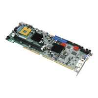
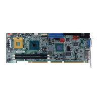
IEI Technology WSB-9452 User Manual (266 pages)
Full-Size PICMG 1.0 CPU Card with Intel Core2 Duo/Solo, VGA/DVI, Dual PCIe GbE, SATA 3Gb/s and Audio
Brand:
IEI Technology
| Category:
Motherboard
| Size: 9.94 MB
Table of Contents
User Manual
1
Table of Contents
6
1 Introduction
19
Wsb-9452 Cpu Card Overview
20
WSB-9452 Model Variations
20
WSB-9452 CPU Card Applications
20
WSB-9452 CPU Card Benefits
20
Table 1-1: WSB-9452 Model Variations
20
WSB-9452 CPU Card Features
21
Wsb-9452 Cpu Card Overview
22
Figure 1-1: Data Flow Block Diagram
22
WSB-9452 CPU Card Connectors
23
Technical Specifications
24
Table 1-2: Technical Specifications
26
2 Detailed Specifications
27
Compatible Iei Backplanes
28
Cpu Support
28
Intel ® Core™2 Duo
28
Table 2-1: Supported Cpus
28
Intel ® Core™ Duo
29
Intel Core™ solo
29
Intel ® Celeron ® M
30
On-Board Chipsets
30
Northbridge and Southbridge Chipsets
30
Intel ® 945GME Northbridge Chipset
30
Intel ICH7-M Southbridge Chipset
31
Graphics Support
32
Intel ® GMA 950
32
Analog VGA
33
Digital LVDS
33
Digital Visual Interface (DVI)
33
Data Flow
34
Figure 2-1: Data Flow Block Diagram
34
Memory Support
35
Pci Bus Interface Support
35
Gbe Ethernet Connection
36
Drive Interfaces
36
SATA Drives
36
IDE HDD Interfaces
37
Floppy Disk Drive (FDD)
37
SATA 3Gb/S and RAID Functionality (SATA3 and SATA4 Only)
37
Serial Ports
38
Real Time Clock
38
System Monitoring
39
Infrared Data Association (Irda) Interface
39
Usb Interfaces
39
Operating Temperature and Temperature Control
40
Optional Audio Interface
40
Power Consumption
40
Table 2-2: Power Consumption
40
Packaged Contents and Optional Accessory Items
41
Package Contents
41
Special Items
41
Optional Accessory Items
42
3 Unpacking
43
Anti-Static Precautions
44
Unpacking
44
Unpacking Precautions
44
Unpacking Checklist
45
Package Contents
45
Table 3-1: Package List Contents
46
Optional Items
47
Table 3-2: Package List Contents
47
4 Connectors and Jumpers
48
Peripheral Interface Connectors
49
WSB-9452 CPU Card Layout
49
Table 4-1: Connector and Jumper Locations
49
Peripheral Interface Connectors
50
External Peripheral Interface Connectors
51
Table 4-2: Peripheral Interface Connectors
51
Table 4-3: External Peripheral Interface Connectors
51
On-Board Jumpers
52
Internal Peripheral Connectors
52
ATX-12V Power Source Connector
52
Table 4-4: On-Board Jumpers
52
Figure 4-1: ATX-12V Connector Location
53
Table 4-5: ATX-12V Connector Pinouts
53
Audio Module Connector
54
Figure 4-2: Audio Connector Location
54
Backplane to Mainboard Power Connector
55
Table 4-6: Audio Connector Pinouts
55
Figure 4-3: Backplane to Mainboard Power Connector Location
56
Table 4-7: Backplane to Mainboard Power Pin Outs
56
Battery Connector
57
Figure 4-4: Battery Connector Location
57
CPU Fan Connector
58
Table 4-8: Battery Connector Pinouts
58
Figure 4-5: CPU Fan Connector Location
59
Table 4-9: CPU Fan Connector Pinouts
59
Digital Input/Output (DIO) Connector
60
Figure 4-6: DIO Connector Location
60
DVI (Digital Visual Interface) Connector
61
Table 4-10: Dioconnector Pinouts
61
Figure 4-7: DVI Connector Location
62
FDD Connector
63
Table 4-11: DVI Connector Pinouts
63
Figure 4-8: FDD Connector Location
64
Front Panel Connector
65
Table 4-12: FDD Connector Pinouts
65
Figure 4-9: Front Panel Connector Location
66
Table 4-13: Front Panel Connector Location
66
IDE Connectors
67
Figure 4-10: IDE Connectors Location
67
Inverter Connector
68
Table 4-14: IDE Connector Pinouts
68
Figure 4-11: Inverter Connector Location
69
Table 4-15: Inverter Connector Pinouts
69
Irda Interface Connector
70
Figure 4-12: Irda Interface Connector Location
70
Keyboard Connector
71
Table 4-16: Irda Interface Connector Pinouts
71
Figure 4-13: Keyboard Connector Location
72
Table 4-17: KB1 Connector Pinouts
72
LVDS Connector
73
Figure 4-14: LVDS Connector Location
73
Parallel Port Connector
74
Table 4-18: LVDS Connector Pinouts
74
Figure 4-15: Parallel Port Connector Location
75
PCI Express Mini Card Connector
76
Table 4-19: Parallel Port Connector Pinouts
76
Figure 4-16: PCI Express Mini Card Connector Location
77
Serial Port Connectors
78
Table 4-20: PCI Express Mini Card Connector Pinouts
78
Figure 4-17: RS-232 Serial Port Connector Location
79
Table 4-21: RS-232 Serial Port Connector Pinouts
79
SATA Drive Connectors
80
Figure 4-18: SATA Connectors Location
80
SPI Flash Connector
81
Table 4-22: SATA Connectors Pinouts
81
Figure 4-19: SPI Flash Connector Location
82
Table 4-23: SPI Flash Connector Pinouts
82
Trusted Platform Module Connector
83
Figure 4-20: TPM Connector Location
83
TV out Connector
84
Table 4-24: TPM Connector Pinouts
84
Figure 4-21: TV out Connector Location
85
Table 4-25: TV out Connector Pinouts
85
USB Connectors
86
Figure 4-22: USB Port Connector Location
86
External Peripheral Interfaceconnectors
87
Figure 4-23: External Peripheral Interface Connector Panel
87
Table 4-26: USB Port Connector Pinouts
87
LAN Connectors
88
Table 4-27: LAN Pinouts
88
Table 4-28: Ethernet Connector Pinouts
88
Figure 4-24: RJ-45 Ethernet Connector
89
Mini-DIN 6 PS/2 Connector
89
Figure 4-25: Mini-DIN 6 PS/2 Connector
90
Table 4-29: Mini-DIN 6 PS/2 Connector
90
USB Connector
90
Figure 4-26: VGA Connector
91
Table 4-30: USB Port Pinouts
91
VGA Connector
91
Table 4-31: VGA Connector Pinouts
92
5 Installation and Configuration
93
Anti-Static Precautions
94
Installation Considerations
94
Installation Notices
94
Unpacking
95
Unpacking Precautions
95
Checklist
96
Wsb-9452 Cpu Card Installation
97
Socket 478 CPU Installation
98
Figure 5-1: Make Sure the CPU Socket Retention Screw Is Unlocked
99
Cooling Kit (CF-479B-RS ) Installation
100
Figure 5-2: Lock the CPU Socket Retention Screw
100
Figure 5-3: IEI CF-479B-RS Cooling Kit
100
Figure 5-4: Install Support Bracket
101
Figure 5-5: Align the Cooling Kit
102
DIMM Module Installation
103
Purchasing the Memory Module
103
Figure 5-6: Secure the Cooling Kit
103
DIMM Module Installation
104
Figure 5-7: Installing the DIMM Module
105
Peripheral Device Connection
106
Table 5-1: IEI Provided Cables
106
IDE Disk Drive Connectors (IDE1, IDE2)
107
Figure 5-8: Connection of IDE Connector
108
Floppy Drive Connector (FDD1)
109
SATA Drive Connection
109
Figure 5-9: SATA Drive Cable Connection
110
Installing the RS-232 Cable
111
Figure 5-10: SATA Drive Connection
111
USB 2.0 Cable Connection
112
Figure 5-11: Dual RS-232 Cable Installation
112
Figure 5-12: USB Cable Installation
113
On-Board Jumpers
114
AT Power Select Jumper Settings
114
Figure 5-13 Jumper
114
Table 5-2: On-Board Jumpers
114
Figure 5-14: at Power Select Jumper Location
115
Table 5-3: at Power Select Jumper Settings
115
Clear CMOS Jumper
116
Table 5-4: Clear CMOS Jumper Settings
116
LVDS LCD Voltage Selection
117
Figure 5-15: Clear CMOS Jumper
117
Table 5-5: LVDS LCD Voltage Selection Jumper Settings
118
Chassis Installation
119
Figure 5-16: LVDS Voltage Selection Jumper Pinout Locations
119
Rear Panel Connectors
120
Keyboard and Mouse Connection
120
VGA Port Installation
120
Ethernet Connection
120
USB Connection
120
6 Ami Bios Setup
121
Introduction
122
Starting Setup
122
Using Setup
122
Getting Help
123
Unable to Reboot after Configuration Changes
123
BIOS Menu Bar
123
Table 6-1: BIOS Navigation Keys
123
Main
124
BIOS Menu 1: Main
124
Advanced
125
BIOS Menu 2: Advanced
126
BIOS Menu 3: CPU Configuration
127
CPU Configuration
127
IDE Configuration
128
BIOS Menu 4: IDE Configuration
129
BIOS Menu 5: IDE Master and IDE Slave Configuration
131
IDE Master, IDE Slave
131
BIOS Menu 6: Floppy Configuration
135
Floppy Configuration
135
BIOS Menu 7: Super IO Configuration
136
Super IO Configuration
136
BIOS Menu 8: Hardware Health Configuration
140
Hardware Health Configuration
140
ACPI Configuration
143
BIOS Menu 9: ACPI Configuration
143
BIOS Menu 10: General ACPI Configuration
144
General ACPI Configuration
144
APM Configuration
146
BIOS Menu 11: APM Configuration
146
BIOS Menu 12: MPS Configuration
149
MPS Configuration
149
BIOS Menu 13: Remote Access Configuration
150
Remote Access Configuration
150
BIOS Menu 14: Trusted Computing Configuration
155
Trusted Computing
155
BIOS Menu 15: USB Configuration
156
USB Configuration
156
Pci/Pnp
159
BIOS Menu 16: Pci/Pnp Configuration
161
Boot
167
Boot Settings Configuration
167
BIOS Menu 17: Boot
167
BIOS Menu 18: Boot Settings Configuration
168
Boot Device Priority
171
BIOS Menu 19: Boot Device Priority Settings
171
Hard Disk Drives
172
BIOS Menu 20: Hard Disk Drives
172
Removable Drives
173
BIOS Menu 21: Removable Drives
174
Security
175
BIOS Menu 22: Security
175
Chipset
177
BIOS Menu 23: Chipset
177
Northbridge Configuration
178
BIOS Menu 24: Northbridge Chipset Configuration
178
BIOS Menu 25: Video Function Configuration
181
Video Function Configuration
181
BIOS Menu 26:Southbridge Chipset Configuration
186
Southbridge Configuration
186
Exit
189
BIOS Menu 27:Exit
189
7 Software Drivers
191
Available Software Drivers
192
Chipset Driver Installation
192
Figure 7-1: Installshield Wizard Preparation Screen
193
Figure 7-2: Welcome Screen
193
Figure 7-3: License Agreement
194
Figure 7-4: Readme Information
195
Figure 7-5: Restart the Computer
196
Vga Driver
197
Figure 7-6: Starting Install Shield Wizard Screen
197
Figure 7-7: Preparing Setup Screen
198
Figure 7-8: VGA Driver Installation Welcome Screen
199
Figure 7-9: VGA Driver License Agreement
200
Figure 7-10: VGA Driver Installing Notice
200
Figure 7-11: VGA Driver Installation Complete
201
Realtek LAN Driver (for Gbe LAN) Installation
202
Figure 7-12: Access Windows Control Panel
202
Figure 7-13: Double Click the System Icon
203
Figure 7-14: Double Click the Device Manager Tab
204
Figure 7-15: Device Manager List
204
Figure 7-16: Search for Suitable Driver
205
Figure 7-17: Locate Driver Files
206
Figure 7-18: Location Browsing Window
207
Realtek Hd Audio Driver (Alc888) Installation
208
BIOS Setup
208
Driver Installation
208
Figure 7-19: 4-AUDIO\AC-Kit888Hd\Windows Folder
209
Figure 7-20: HD Audio Driver Setup Extracting Files
210
Figure 7-21: HD Audio Driver Setup Welcome Screen
211
Figure 7-22: HD Audio Driver Installation Complete
212
Realtek Ac`97 Audio Driver (Alc665) Installation
213
BIOS Setup
213
Driver Installation
213
Figure 7-23: CD 4-AUDIO\AC-Kit08R\Windows Folder
214
Figure 7-24: AC`97 Audio Driver Install Shield Wizard Starting
214
Figure 7-25: AC`97 Audio Driver Setup Preparation
215
Figure 7-26: AC`97 Audio Driver Welcome Screen
216
Figure 7-27: AC`97 Audio Driver Software Configuration
217
Figure 7-28: AC`97 Audio Driver Digital Signal
218
Figure 7-29: AC`97 Audio Driver Installation Begins
219
Figure 7-30: AC`97 Audio Driver Installation Complete
220
Abios Configuration Options
221
Bios Configuration Options
221
A.1 Bios C Onfiguration O Ptions
222
Bwatchdog Timer
226
Cexternal Ac'97 Audio Codec
229
Introduction
230
C.1 I Ntroduction
230
Physical Connection
232
Driver Installation
232
C.2 P Hysical C Onnection
232
Sound Effect Configuration
234
Sound Effect
235
Environment Simulation
235
Karaoke Mode
237
C.7 Karaoke Mode
237
Equalizer Selection
238
Speaker Configuration
239
Speaker Test
240
S/PDIF-In & S/PDIF-Out
241
C.11 S/Pdif-I N & S/Pdif-O Ut
241
Connector Sensing
242
Hrtf Demo
245
Microphone Effect
245
C.13 HRTF Demo
245
General
246
C.15 G Eneral
246
Djmicron Raid Setup
247
Introduction
248
RAID Support
248
What Is RAID
248
D.1 I Ntroduction
248
Raid Setup
249
Introduction
249
Install SATA Drives
249
Configure the SATA Controller in BIOS
249
Configure the RAID BIOS
250
Create a RAID Volume
251
Delete a RAID Volume
255
Revert an HDD to Non-RAID
257
Solve Mirror Conflict
259
Rebuild Mirror Drive
260
Save and Exit Setup
261
Exit Without Saving
261
Install the os
262
Advertisement
IEI Technology WSB-9452 Quick Installation Manual (11 pages)
Brand:
IEI Technology
| Category:
Single board computers
| Size: 0.15 MB
Advertisement
Related Products
IEI Technology WSB-G41A
IEI Technology WSB-Q354
IEI Technology WSB-9454
IEI Technology WSB-G41A-R11
IEI Technology WSB-9152
IEI Technology WSB-H810
IEI Technology WAFER-BW-N2-R10
IEI Technology WAFER-KBN-1
IEI Technology WAFER-LX-800-R10
IEI Technology WAFER-LX-CENET050
IEI Technology Categories
Motherboard
Touch Panel
Computer Hardware
Single board computers
Desktop
More IEI Technology Manuals
Login
Sign In
OR
Sign in with Facebook
Sign in with Google
Upload manual
Upload from disk
Upload from URL