Sign In
Upload
Manuals
Brands
IEI Technology Manuals
Motherboard
WSB-H810
IEI Technology WSB-H810 Manuals
Manuals and User Guides for IEI Technology WSB-H810. We have
1
IEI Technology WSB-H810 manual available for free PDF download: User Manual
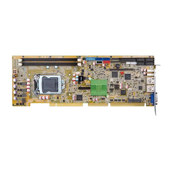
IEI Technology WSB-H810 User Manual (165 pages)
Full-size PICMG 1.0 CPU card supports LGA1150 Intel Core i7/i5/i3, Pentium and Celeron CPU per Intel H81, DDR3, VGA/iDP, Dual Intel GbE, USB 3.0, SATA 6Gb/s, PCIe Mini, mSATA, RS-232, HD Audio and RoHS
Brand:
IEI Technology
| Category:
Motherboard
| Size: 11.03 MB
Table of Contents
User Manual
1
Table of Contents
5
Introduction
15
Introduction
16
Figure 1-1: WSB-H810
16
Features
17
Connectors
18
Figure 1-2: Connectors
18
Dimensions
19
Figure 1-3: WSB-H810 Dimensions (MM)
19
Figure 1-4: External Interface Panel Dimensions (MM)
20
Data Flow
21
Figure 1-5: Data Flow Diagram
21
Technical Specifications
22
Table 1-1: WSB-H810 Specifications
24
Packing List
25
Anti-Static Precautions
26
Unpacking Precautions
26
Packing List
27
Table 2-1: Packing List
27
Optional Items
28
Table 2-2: Optional Items
30
Connectors
31
Peripheral Interface Connectors
32
WSB-H810 Layout
32
Figure 3-1: Connectors and Jumpers
32
Peripheral Interface Connectors
33
External Interface Panel Connectors
34
Table 3-1: Peripheral Interface Connectors
34
Table 3-2: Rear Panel Connectors
34
Internal Peripheral Connectors
35
Power Connector
35
ATX Power Supply Enable Connector
35
Figure 3-2: +12V Power Connector Pinout Location
35
Table 3-3: +12V Power Connector Pinouts
35
Audio Kit Connector
36
Figure 3-3: ATX Power Supply Enable Connector Location
36
Figure 3-4: Audio Kit Connector Location
36
Table 3-4: ATX Power Supply Enable Connector Pinouts
36
Battery Connector
37
Figure 3-5: Battery Connector Location
37
Table 3-5: Audio Kit Connector Pinouts
37
Chassis Intrusion Connector
38
DDR3 DIMM Slots
38
Figure 3-6: Chassis Intrusion Connector Location
38
Table 3-6: Battery Connector Pinouts
38
Table 3-7: Chassis Intrusion Connector Pinouts
38
Digital I/O Connector
39
Figure 3-7: DDR3 DIMM Slot Locations
39
Figure 3-8: Digital I/O Connector Location
39
Table 3-8: Digital I/O Connector Pinouts
39
EC Debug Connector
40
Fan Connector (CPU)
40
Figure 3-9: EC Debug Connector Location
40
Table 3-9: EC Debug Connector Pinouts
40
Fan Connector (System)
41
Figure 3-10: CPU Fan Connector Location
41
Table 3-10: CPU Fan Connector Pinouts
41
Front Panel Connector
42
Figure 3-11: System Fan Connector Location
42
Figure 3-12: Front Panel Connector Location
42
Table 3-11: System Fan Connector Pinouts
42
I 2 C Connector
43
Figure 3-13: I 2 C Connector Location
43
Table 3-12: Front Panel Connector Pinouts
43
Table 3-13: I 2 C Connector Pinouts
43
Infrared Connector (Reserved)
44
Internal Displayport Connector
44
Figure 3-14: Infrared Connector Location
44
Table 3-14: Infrared Connector Pinouts
44
Keyboard and Mouse Connector
45
Figure 3-15: Internal Displayport Connector Location
45
Table 3-15: Internal Displayport Connector Pinouts
45
LAN LED Connectors
46
Figure 3-16: Keyboard and Mouse Connector Location
46
Table 3-16: Keyboard and Mouse Connector Pinouts
46
Msata Slot
47
Figure 3-17: LAN LED Connector Locations
47
Table 3-17: LAN1 LED Connector (LED_LAN1) Pinouts
47
Table 3-18: LAN2 LED Connector (LED_LAN2) Pinouts
47
Figure 3-18: Msata Slot Location
48
Parallel Port Connector
49
Figure 3-19: Parallel Port Connector Location
49
Table 3-19: Msata Slot Pinouts
49
Pcie Mini Slot
50
Figure 3-20: Pcie Mini Slot Location
50
Table 3-20: Parallel Port Connector Pinouts
50
SATA 3Gb/S Drive Connector
51
Table 3-21: Pcie Mini Slot Pinouts
51
SATA 6Gb/S Drive Connectors
52
Figure 3-21: SATA 3Gb/S Drive Connector Location
52
Table 3-22: SATA 3Gb/S Drive Connector Pinouts
52
Serial Port Connectors, RS-232
53
Figure 3-22: SATA 6Gb/S Drive Connector Locations
53
Figure 3-23: Serial Port Connector Locations
53
Table 3-23: SATA 6Gb/S Drive Connector Pinouts
53
Serial Port Connector, RS-422/485
54
Figure 3-24: RS-422/485 Connector Location
54
Table 3-24: Serial Port Connector Pinouts
54
Table 3-25: RS-422/485 Connector Pinouts
54
Smbus Connector
55
Figure 3-25: Smbus Connector Location
55
Table 3-26: DB-9 RS-422/485 Pinouts
55
Table 3-27: Smbus Connector Pinouts
55
SPI Flash Connector
56
SPI Flash Connector (EC)
56
Figure 3-26: SPI Flash Connector Location
56
Table 3-28: SPI Flash Connector Pinouts
56
TPM Connector
57
Figure 3-27: SPI EC Flash Connector Location
57
Figure 3-28: TPM Connector Location
57
Table 3-29: SPI EC Flash Connector Pinouts
57
USB 2.0 Connectors
58
Figure 3-29: USB 2.0 Connector Pinout Locations
58
Table 3-30: TPM Connector Pinouts
58
USB 2.0 Connector (Type A)
59
USB 3.0 Connector
59
Figure 3-30: USB 2.0 Connector (Type A) Pinout Location
59
Table 3-31: USB 2.0 Connector Pinouts
59
Table 3-32: USB 2.0 Connector (Type A) Pinouts
59
Figure 3-31: USB 3.0 Connector Location
60
Table 3-33: USB 3.0 Connector Pinouts
60
External Peripheral Interface Connector Panel
61
Ethernet Connectors
61
Figure 3-32: External Peripheral Interface Connector
61
Figure 3-33: Ethernet Connector
61
Table 3-34: LAN Pinouts
61
USB 2.0 Connectors
62
VGA Connector
62
Table 3-35: Connector Leds
62
Table 3-36: USB 2.0 Port Pinouts
62
Figure 3-34: VGA Connector
63
Table 3-37: VGA Connector Pinouts
63
Installation
64
Anti-Static Precautions
65
Installation Considerations
65
Socket Lga1150 Cpu Installation
67
Figure 4-1: Disengage the CPU Socket Load Lever
67
Figure 4-2: Remove Protective Cover
68
Figure 4-3: Insert the Socket LGA1150 CPU
69
Figure 4-4: Close the Socket LGA1150
69
Socket Lga1150 Cooling Kit Installation
70
Figure 4-5: Cooling Kit Support Bracket
70
DIMM Installation
71
Figure 4-6: DIMM Installation
71
Full-Size Pcie Mini Card Installation
72
Figure 4-7: Removing the Retention Screw and Standoff for a Half-Size Pcie Mini Card
72
Figure 4-8: Removing the Retention Screw
73
Figure 4-9: Inserting the Full-Size Pcie Mini Card into the Slot at an Angle
73
Half-Size Pcie Mini Card Installation
74
Figure 4-10: Securing the Full-Size Pcie Mini Card
74
Figure 4-11: Removing the Retention Screw
75
Figure 4-12: Inserting the Half-Size Pcie Mini Card into the Slot at an Angle
75
Msata Card Installation
76
Figure 4-13: Securing the Half-Size Pcie Mini Card
76
Figure 4-14: Removing the Retention Screws
77
Figure 4-15: Inserting the Msata Card into the Slot at an Angle
77
System Configuration
78
AT/ATX Power Mode Setting
78
Figure 4-16: Securing the Msata Card
78
Figure 4-17: AT/ATX Power Mode Switch Location
78
Clear CMOS Button
79
Flash Descriptor Security Override
79
Figure 4-18: Clear CMOS Button Location
79
Table 4-1: AT/ATX Power Mode Switch Settings
79
Table 4-2: Flash Descriptor Security Override Jumper Settings
79
USB Power Selection
80
Figure 4-19: Flash Descriptor Security Override Jumper Location
80
Table 4-3: BIOS Options and Configured USB Ports
80
Chassis Installation
81
Airflow
81
CPU Card Installation
81
Table 4-4: USB Power Source Setup
81
Internal Peripheral Device Connections
82
SATA Drive Connection
82
Figure 4-20: SATA Drive Cable Connection
82
Figure 4-21: SATA Power Drive Connection
83
Bios
84
Introduction
85
Starting Setup
85
Using Setup
85
Getting Help
86
Unable to Reboot after Configuration Changes
86
BIOS Menu Bar
86
Table 5-1: BIOS Navigation Keys
86
Main
87
Advanced
88
ACPI Settings
89
RTC Wake Settings
90
Trusted Computing
92
CPU Configuration
93
SATA Configuration
95
USB Configuration
97
F81866 Super IO Configuration
98
Serial Port N Configuration
98
Irda Configuration
103
Parallel Port Configuration
105
Iwdd H/W Monitor
106
Smart Fan Mode Configuration
107
Serial Port Console Redirection
108
BIOS Menu 15: Serial Port Console Redirection
109
Iei Feature
111
Chipset
112
PCH-IO Configuration
113
Table 5-2: BIOS Options and Configured USB Ports
114
PCI Express Configuration
115
PCH Azalia Configuration
117
System Agent (SA) Configuration
118
Graphics Configuration
118
BIOS Menu 23: Graphics Configuration
119
Lcd Control
120
NB Pcie Configuration
121
Memory Configuration
122
Boot
123
Security
125
Save & Exit
125
BIOS Menu 29: Save & Exit
126
Software Drivers
127
Available Software Drivers
128
Software Installation
128
Chipset Driver Installation
129
Figure 6-1: Chipset Driver Welcome Screen
129
Figure 6-2: Chipset Driver License Agreement
130
Figure 6-3: Chipset Driver Read Me File
130
Figure 6-4: Chipset Driver Setup Progress
131
Figure 6-5: Chipset Driver Installation Finish Screen
131
Graphics Driver Installation
132
Figure 6-6: Graphics Driver Installshield Wizard
132
Figure 6-7: Graphics Driver - Extracting Files
133
Figure 6-8: Graphics Driver Welcome Screen
133
Figure 6-9: Graphics Driver License Agreement
134
Figure 6-10: Graphics Driver Read Me File
134
Figure 6-11: Graphics Driver Setup Progress
135
Figure 6-12: Graphics Driver Installation Finish Screen
135
Lan Driver Installation
136
Figure 6-13: Windows Control Panel
136
Figure 6-14: System Control Panel
136
Figure 6-15: Device Manager List
137
Figure 6-16: Update Driver Software Window
138
Figure 6-17: Locate Driver Files
138
Audio Driver Installation
139
Figure 6-18: LAN Driver Installation
139
Figure 6-19: Audio Driver - Extracting Files
140
Figure 6-20: Audio Driver Installation Welcome Screen
140
Usb 3.0 Driver Installation
141
Figure 6-21: Audio Driver Installation Complete
141
Figure 6-22: USB 3.0 Driver Welcome Screen
142
Figure 6-23: USB 3.0 Driver License Agreement
142
Figure 6-24: USB 3.0 Driver Read Me File
143
Figure 6-25: USB 3.0 Driver Setup Operations
143
Figure 6-26: USB 3.0 Driver Installation Finish Screen
144
A Regulatory Compliance
145
B Product Disposal
147
CBIOS Options
149
D Terminology
153
E Digital I/O Interface
157
Introduction
158
E.1 I Ntroduction
158
Assembly Language Sample 1
159
Assembly Language Sample 2
159
E.2 a Ssembly L Anguage S Ample 1
159
F Watchdog Timer
160
G Hazardous Materials Disclosure
163
Advertisement
Advertisement
Related Products
IEI Technology WSB-G41A
IEI Technology WSB-Q354
IEI Technology WSB-9454
IEI Technology WSB-9452
IEI Technology WSB-G41A-R11
IEI Technology WSB-9152
IEI Technology WAFER-US15WP
IEI Technology WAFER-LUKE
IEI Technology WAFER-BW Series
IEI Technology WAFER-PV-D5251
IEI Technology Categories
Motherboard
Touch Panel
Computer Hardware
Single board computers
Desktop
More IEI Technology Manuals
Login
Sign In
OR
Sign in with Facebook
Sign in with Google
Upload manual
Upload from disk
Upload from URL