Sign In
Upload
Manuals
Brands
Emerson Manuals
Controller
Unidrive M702
Emerson Unidrive M702 Manuals
Manuals and User Guides for Emerson Unidrive M702. We have
6
Emerson Unidrive M702 manuals available for free PDF download: User Manual, Installation Manual, Getting Started Manual, Control Getting Started Manual
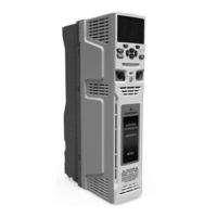
Emerson Unidrive M702 User Manual (285 pages)
Universal Variable Speed AC drive for induction and permanent magnetmotors
Brand:
Emerson
| Category:
Controller
| Size: 25 MB
Table of Contents
Product View
1
General Information
2
How to Use this Guide
3
Table of Contents
4
1 Safety Information
8
Warnings, Cautions and Notes
8
Electrical Safety - General Warning
8
System Design and Safety of Personnel
8
Environmental Limits
8
Access
8
Fire Protection
8
Compliance with Regulations
8
Motor
8
Mechanical Brake Control
8
Electrical Installation
9
2 Product Information
10
Model Number
10
Introduction
10
Ratings
11
Operating Modes
14
Typical Short Term Overload Limits
14
Open Loop Mode
14
RFC-A Mode/Rfc- S
14
Compatible Position Feedback Devices
15
Drive Features
16
Nameplate Description
17
Options Available with the Drive
17
Option Module Identification
18
Keypad Identification
18
Items Supplied with the Drive
19
Additional Options
19
3 Mechanical Installation
20
Cooling
20
Fire Protection
20
Environmental Protection
20
Safety Information
20
Planning the Installation
20
Terminal Cover Removal
21
Location and Identification of Terminal Covers
22
Removing the Finger-Guard and DC Terminal Cover Break-Outs
26
Installing / Removing Option Modules and Keypads
27
Removal of a Standard Option Module
28
Installation and Removal of a Large Option Module
28
Installation and Removal of the KI-Keypad
29
Dimensions and Mounting Methods
30
Surface Mounting
30
Mounting Brackets
37
Enclosure for Standard Drives
38
Recommended Spacing between the Drives
38
Enclosure Sizing
39
Calculating the Size of a Sealed Enclosure
39
Calculating the Air-Flow in a Ventilated Enclosure
39
Enclosure Design and Drive Ambient Temperature
40
Heatsink Fan Operation
40
Enclosing Standard Drive for High Environmental Protection
40
Installing the Gasket
41
Installation of High IP Insert
41
Through Panel Mounting
41
Heatsink Mounted Brake Resistor
43
Internal Braking Resistor Installation
43
External EMC Filter
45
Electrical Terminals
47
Location of the Power and Ground Terminals
47
Terminal Sizes and Torque Settings
48
Routine Maintenance of the Drive
48
Plug-In Terminal Block Maximum Cable Sizes
48
External EMC Filter Terminal Data
48
Real Time Clock Battery Replacement
49
Fan Removal Procedure
50
4 Electrical Installation
51
Power Connections
51
AC and DC Connections
51
Ground Connections
54
AC Supply Requirements
55
Supplying the Drive with DC
56
Supplies Requiring Line Reactors
56
Input Inductor Calculation
56
DC Bus Paralleling
57
24 VDC Supply
57
Low Voltage Operation
58
Heatsink Fan Supply
58
AC Input Current and Fuse Ratings (200 V)
59
Input Current and Fuse Ratings (400 V)
60
AC Input Current and Fuse Ratings (575 V)
60
Input Current and Fuse Ratings (690 V)
60
Cable Ratings
61
Output Circuit and Motor Protection
63
Cable Types and Lengths
63
High-Capacitance / Reduced Diameter Cables
64
Motor Winding Voltage
64
Multiple Motors
64
Braking
65
Output Contactor
65
Heatsink Mounted Braking Resistor
65
Braking Resistor Overload Protection Parameter Settings
66
Heatsink Mounted Braking Resistor Data
66
External Braking Resistor
67
Thermal Protection Circuit for the Braking Resistor
67
EMC (Electromagnetic Compatibility)
68
Braking Resistor Software Overload Protection
68
Ground Leakage
68
Grounding Hardware
69
Drive and EMC Filter Cross Reference
69
Installation of Grounding Clamp
69
Internal EMC Filter
70
General Requirements for EMC
72
Feedback Device Cable Shielding
73
Supply and Ground Cable Clearance
75
Grounding the Drive, Motor Cable Shield and Filter
75
Sensitive Signal Circuit Clearance
75
Grounding the Motor Cable Shield
75
Variations in the EMC Wiring
76
Interruptions to the Motor Cable
76
Using a Motor Isolator / Disconnect-Switch
76
Surge Immunity of Control Circuits
76
Communications Connections
77
Ethernet Fieldbus Communications
77
Surge Suppression
77
Control Connections
78
Control Terminal Specification
79
Position Feedback Connections
80
Position Feedback Connection Details
82
Position Feedback Terminal Specifications
84
Safe Torque off (STO)
86
Sincos Encoder Resolution
86
Keypad Operation
88
Control Buttons
88
5 Getting Started
88
Understanding the Display
88
Quick Access Mode
89
Keypad Shortcuts
89
Display Modes
89
Menu Structure
90
Mode Examples
90
Menu 0
91
Advanced Menus
91
KI-Keypad Set-Up Menu
92
Display Messages
92
Alarm Indications
92
Changing the Operating Mode
93
Saving Parameters
93
Restoring Parameter Defaults
93
Parameter Access Level and Security
93
Displaying Parameters with Non-Default Values Only
94
Displaying Destination Parameters Only
94
Communications
94
User Security Level / Access Level
94
6 Basic Parameters
96
Menu 0: Basic Parameters
96
Parameter Descriptions
100
7 Running the Motor
102
Quick Start Connections
102
Changing the Operating Mode
102
Minimum Connections to Get the Motor Running in any Operating Mode
103
Quick Start Commissioning / Start-Up
107
Open Loop
107
RFC - a Mode (with Position Feedback)
108
RFC-A Mode (Sensorless Control)
109
RFC-S Mode (with Position Feedback)
110
Setting up a Feedback Device
111
P1 Position Interface
111
Detailed Feedback Device Commissioning / Start-Up Information
112
P2 Position Interface
114
Encoder Simulation Output Set-Up
115
Software Mode - Incremental Signals
116
Ratio
117
Software Mode - Absolute SSI Data
117
8 Optimization
118
Motor Map Parameters
118
Rated Speed/Number of Motor Pole
118
Rated Power Factor
118
Autotune
119
Open Loop Control Mode
119
Enable Slip Compensation
120
RFC-A Mode
121
Induction Motor with Position Feedback
121
Motor Rated Current
121
Rated Voltage/Frequency
121
Motor Parameter Adaptive Control
122
Current Loop Gains
122
Speed Loop Gains
123
RFC-S Mode
124
Permanent Magnet Motor with Position Feedback
124
Stationary Autotune/Rotating Autotune
124
Inertia Measurement Test
124
Maximum Motor Rated Current
127
Current Limits
127
Motor Thermal Protection
127
Switching Frequency
128
High Speed Operation
128
Encoder Feedback Limits
128
Permanent Magnet Motor High Speed Operation
128
Quasi-Square Wave (Open-Loop Only)
129
Unidrive M702 User Guide Issue Number
129
9 NV Media Card Operation
130
SMARTCARD Support
130
Introduction
130
Transferring Data
131
Writing to the SMARTCARD
131
Reading from the SMARTCARD
131
Booting up from the SMARTCARD on Every Power up
131
NV Media Card Parameters
132
Data Block Header Information
132
NV Media Card Trips
133
Onboard PLC and Machine Control Studio
134
Benefits
134
Features
134
Onboard PLC Parameters
135
Onboard PLC Trips
135
11 Advanced Parameters
136
Feature Look-Up Table
137
Parameter Ranges and Variable Minimum/Maximums
139
Menu 1: Frequency / Speed Reference
146
Menu 2: Ramps
150
Menu 3: Frequency Slaving, Speed Feedback and Speed Control
153
Freeze System Logic
158
P1 Position Feedback Interface Thermistor Input
159
Encoder Simulation
159
Menu 4: Torque and Current Control
164
Menu 4 RFC-A Logic Diagram
165
Menu 4 RFC-S Logic Diagram
166
Menu 5: Motor Control
168
Menu 5 Open-Loop Logic Diagram
168
Menu 5 RFC-A, RFC-S Logic Diagram
170
Menu 6: Sequencer and Clock
174
Menu 6 Logic Diagram
174
Menu 6 Low Voltage Operation
175
Menu 7: Temperature Monitoring
178
Menu 8: Digital I/O
180
Menu 8 Logic Diagram
180
Menu 9: Programmable Logic, Motorized Pot, Binary Sum and Timers
184
Menu 9 Logic Diagram: Scope Function
187
Menu 10: Status and Trips
190
Menu 11: General Drive Set-Up
192
Menu 12 Logic Diagram
194
Menu 12: Threshold Detectors, Variable Selectors and Brake Control Function
194
Open-Loop Brake Function
196
Open-Loop Brake Sequence
197
RFC-A Mode with Brake Controller Mode
198
RFC-A Brake Sequence
199
RFC-A Mode (Brake Controller (12.052) = 0) and RFC-S Mode
200
Menu 13: Standard Motion Controller
202
Menu 13 Logic Diagram
202
Menu 14: User PID Controller
206
Menu 14 Logic Diagram
206
Menus 15, 16 and 17: Option Module Set-Up
210
Location of Option Module Slots and Their Corresponding Menu Numbers
210
Menu 18: Application Menu 1
211
Menu 19: Application Menu 2
212
Menu 20: Application Menu 3
213
Menu 21: Second Motor Parameters
214
Menu 22: Additional Menu 0 Set-Up
216
Menu 24: Ethernet Status and Monitoring
217
Slot 4 Menu 0: Ethernet Status and Monitoring
218
Slot 4 Menu 2: Ethernet Configuration
218
Slot 4 Menu 9: Resources
219
Slot 4 Menu 10: Easy Mode
220
Slot 4 Menu 11: Synchronization
222
Slot 4 Menu 15: Modbus
223
Slot 4 Menu 20: Ethernet/Ip
224
Menu 21 Ethernet/Ip in Mappings
225
Menu 22 Ethernet/Ip out Mappings
225
Menu 23 Ethernet/Ip Fault Values
226
12 Technical Data
227
Drive Technical Data
227
Maximum Permissible Continuous Output Current
229
Power Dissipation
232
Line Reactors
235
Motor Requirements
235
Temperature, Humidity and Cooling Method
235
IP / UL Rating
235
Corrosive Gasses
236
Vibration
236
Acoustic Noise
236
Overall Dimensions
236
Weights
237
Input Current, Fuse and Cable Size Ratings
237
AC Input Current and Fuse Ratings
238
Maximum Motor Cable Lengths
242
Minimum Resistances and Power Ratings for Braking Resistor
242
Braking Resistor Resistance and Power Rating
243
Drive Power Terminal Data
243
Electromagnetic Compatibility (EMC)
244
Immunity Compliance
244
Size 3 Emission Compliance
244
Optional External EMC Filters
245
EMC Filter Ratings
245
Overall EMC Filter Dimensions
245
EMC Filter Torque Settings
246
Status Modes (Keypad and LED Status)
247
Trip Indications
247
Identifying a Trip / Trip Source
248
Trips, Sub-Trip Numbers
249
Analog Input 1/2 Current Loss
249
Analog Output Calibration Failed
249
Customization Table for an Application Module Has Changed
249
Position Feedback Direction Incorrect
250
Drive Encoder U Commutation Signal Fail
250
Autotune Test Stopped before Completion
250
Braking Resistor Overload Timed out
250
Advanced Motion Controller CAM Failure
251
NV Media Card Write Fail
251
Menu 0 Parameter Modification Cannot be Saved to NV Media Card
251
NV Media Card File/Data Is Different to the One in the Drive
251
NV Media Card Data Structure Error
252
NV Media Card Has the Read Only Bit Set
252
NV Media Card Full
252
NV Media Card Data Not Found
252
Trip Initiated from the Control Word (06.042)
253
Current Feedback Offset Error
253
Drive Parameters Are Being Changed
253
Power Stage Recognition: Unrecognized Drive Size
253
Default Parameters Have Been Loaded
254
Drive Position Feedback Interface Power Supply Overload
254
Drive Encoder (Feedback) Wire Break
254
Phase Offset Incorrect While Running
255
Feedback Device Comms Failure
255
Checksum or CRC Error
255
Encoder Has Indicated an Error
255
Initialization Failed
256
Position Feedback Interface Has Timed out
256
RFC-S Mode Phasing Failure Due to Incorrect Phase Angle
256
Encoder Could Not be Identified During Auto-Configuration
256
Data Read from the Encoder Is out of Range During Auto-Configuration
257
An External Trip Is Initiated
257
Out of Range of Frequency Has Been Detected in Regen Mode
257
Data Processing Error: CPU Address Error
257
Data Processing Error: Illegal Slot Instruction
258
Data Processing Error: CPU Interrupt Crash
258
Data Processing Error: Free Store Overflow
258
Data Processing Error: Main Program Stack Overflow
258
Data Processing Error: Internal Flash Memory Has Failed
259
Data Processing Error: CPU Register Bank Error
259
Data Processing Error: RTOS Error
259
Data Processing Error: ASIC Is Not Compatible with the Hardware
259
Inductance Measurement out of Range or Motor Saturation Not Detected
260
The Regen Inductor Has Overloaded
260
Digital Output Overload
260
Island Condition Detected in Regen Mode
260
The Load on the Drive Has Fallen below the Low Load Detection Level
261
Output Current Overload Timed out
261
Electronic Nameplate Transfer Has Failed
261
Control Stage over Temperature
261
DC Bus over Temperature
262
Inverter over Temperature Based on Thermal Model
262
Power Stage over Temperature
262
Rectifier over Temperature
263
Instantaneous Output over Current Detected
263
Braking IGBT over Current Detected
263
Power Module over Current Detected from IGBT
263
Snubber Over-Current Detected
264
Option Module Does Not Acknowledge During Drive Mode Changeover
264
Output Phase Loss Detected
264
Motor Speed Has Exceeded the over Speed Threshold
264
Supply Phase Loss
265
DC Bus Voltage Has Exceeded the Peak Level for 15 Seconds
265
Communication Has Been Lost
266
Power System Configuration Data Error
266
Power down Save Error
266
Internal Power Supply Fault
266
24V Internal Power Supply Overload
267
Reserved Trips
267
Measured Resistance Has Exceeded the Parameter Range
267
Ethernet Interface in Slot 4 Has Changed
267
Ethernet Interface in Slot 4 Has Detected a Fault
268
Ethernet Interface in Slot 4 Hardware Fault
269
Ethernet Interface in Slot 4 Has Been Removed
269
Application Menu Customization Conflict Error
269
Option Module in Option Slot X Has Changed
269
Option Module X Hardware Fault
270
Option Module in Option Slot X Has Been Removed
270
Option Module Watchdog Function Service Error
270
Hardware Trip Has Occurred During Last Power down
270
RAM Allocation Error
271
Internal Thermistor Has Failed
271
Brake Resistor over Temperature
271
Motor Thermistor Short Circuit
271
Motor Thermistor Over-Temperature
272
Drive Has Tripped and the Cause of the Trip Is Undefined
272
User 24 V Supply Is Not Present on Control Terminals (1,2)
272
On Board User Program Error
273
User Save Error / Not Completed
274
Supply Voltage out of Range Detected in Regen Mode
274
User Generated Trip
274
Trip Generated by an Onboard User Program
274
Serial Communications Look up Table
275
Internal / Hardware Trips
276
Trip Categories
276
Status Indications
277
Displaying the Trip History
277
Behaviour of the Drive When Tripped
278
14 UL Listing Information
279
Environment
279
Thermal Memory Retention
279
Motor Overload Protection/Motor Overspeed Protection
279
General
279
Mounting
279
Electrical Installation
279
UL Listed Accessories
279
Electrical Ratings
279
Unidrive M702 User Guide Issue Number
279
Index
280
Advertisement
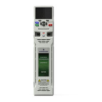
Emerson Unidrive M702 User Manual (198 pages)
Si-Ethernet and Unidrive M - Onboard Ethernet
Brand:
Emerson
| Category:
DC Drives
| Size: 2 MB
Table of Contents
Table of Contents
3
Safety Information
5
Warnings, Cautions and Notes
5
Electrical Safety - General Warning
5
System Design and Safety of Personnel
5
Environmental Limits
5
Compliance with Regulations
6
Motor
6
Adjusting Parameters
6
General Safety Considerations for Remote Operation
6
Introduction
7
Products Covered by this User Guide
7
Features
7
Option Module Identification
8
Product Conformance
8
Conventions Used in this Guide
9
Mechanical Installation
10
Electrical Installation
12
SI-Ethernet Module Information
12
Cabling Considerations
12
Module Grounding
12
Cable Shield Connections
13
Cable
13
Maximum Network Length
13
Network Topology
13
Getting Started
15
Network Design Considerations
15
Addressing
15
Where Do IP Addresses Come from
15
Addressing Etiquette
15
Class Types
16
Generating the Complete Address
17
DHCP Considerations
18
Basic Principles of Routing
18
Set-Up Flow Chart
19
Single Line Parameter Descriptions
20
Parameters
38
Menus
38
Key Features and Protocols
119
PC/PLC Considerations
119
Modbus TCP/IP
119
7.2.7 Fc03 - Read Multiple Registers
123
(Lsb)
124
Function Code 0X03
124
Start Register Address
124
Start Register Address (MSB)
124
Number of 16-Bit Registers (LSB)
125
Number of 16-Bit Registers (MSB)
125
Transaction ID
126
Protocol ID (0=TCP/IP)
126
Rtmoe (Real Time Motion over Ethernet)
129
SI-Ethernet User Guide Issue
130
Non-Cyclic Data Access
138
Ethernet/Ip
144
PC Tools Applications
179
Unidrive M Connect
179
Machine Control Studio
179
Ctscope
180
Syptpro
180
CT OPC Server
181
Security
182
Introduction
182
General Site Security Issues
182
Default Restrictions
182
Diagnostics
183
LED Diagnostics
183
Drive Trip Display Codes
183
Ethernet Sub Trip Codes
184
Ethernet Sub Trip Codes
186
Ethernet Hardware Fault Trip Codes
186
Diagnostic Flow Chart
188
Glossary of Terms
189
Issue Number
194
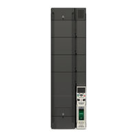
Emerson Unidrive M702 Installation Manual (120 pages)
Unidrive HS series; Unidrive M series. Frame 7 to 10
Brand:
Emerson
| Category:
Controller
| Size: 11 MB
Table of Contents
Table of Contents
3
Issue Number
5
1 Safety Information
8
Warnings, Cautions and Notes
8
Electrical Safety - General Warning
8
System Design and Safety of Personnel
8
Environmental Limits
8
Access
9
Fire Protection
9
Compliance with Regulations
9
Motor
9
Mechanical Brake Control
9
Adjusting Parameters
9
Electrical Installation
10
2 Product Information
11
Introduction
11
Model Number
11
Nameplate Description
12
Ratings
13
Drive Features
16
3 Mechanical Installation
18
Safety Information
18
Planning the Installation
19
Terminal Cover Removal
21
Dimensions and Mounting Methods
23
Enclosure for Standard Drives
28
Enclosure Design and Drive Ambient Temperature
34
Heatsink Fan Operation
34
Enclosing Standard Drive for High Environmental Protection
35
External EMC Filter
39
Terminal Size and Torque Settings
44
Routine Maintenance
45
4 Electrical Installation
50
Power and Ground Connections
51
AC Supply Requirements
54
Supplying the Unidrive M / Unidrive HS Size 7, 8 and 9A Drives with DC / DC Bus Paralleling
59
24 VDC Supply
59
Low Voltage Operation
61
Heatsink Fan Supply
62
Ratings
62
Output Circuit and Motor Protection
63
Braking
66
Ground Leakage
70
EMC (Electromagnetic Compatibility)
71
5 Technical Data
88
Drive Technical Data
88
Optional External EMC Filters
114
6 UL Listing Information
116
UL File Reference
116
Option Modules, Kits and Accessories
116
Enclosure Ratings
116
Mounting
116
Environment
116
Electrical Installation
117
Motor Overload Protection and Thermal Memory Retention
117
Electrical Supply
117
External Class 2 Supply
118
Requirement for Transient Surge Suppression
118
Group Installation and Modular Drive Systems
118
Advertisement
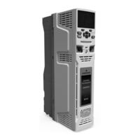
Emerson Unidrive M702 Getting Started Manual (72 pages)
Model sizes 3 to 10
Brand:
Emerson
| Category:
Servo Drives
| Size: 7 MB
Table of Contents
Table of Contents
3
1 Safety Information
5
2 Product Information
8
Model Number
8
Nameplate Description
9
Ratings
10
Drive Features
14
Options / Accessories
15
3 Mechanical Installation
18
Safety Information
18
Fire Protection
18
Mounting Methods
18
Drive Dimensions
19
Surface Mounting
20
Terminal Size and Torque Settings
22
Enclosure
23
EMC Filters
24
4 Electrical Installation
27
Supply Types
28
Ratings
28
Power Connections
29
Ground Connections
35
Position Feedback Connections
35
Braking Resistor Values
37
Communications Connections
38
Shield Connections
38
Control Connections
39
5 Getting Started
40
Understanding the Display
40
Keypad Operation
41
Menu 0
42
Menu Structure
42
Advanced Menus
43
Changing the Operating Mode
44
Saving Parameters
44
Restoring Parameter Defaults
45
Displaying Parameters with Non-Default Values Only
45
Displaying Destination Parameters Only
45
Parameter Access Level and Security
45
6 Basic Parameters (Menu 0)
46
Parameter Descriptions
48
7 Running the Motor
52
Quick Start Connections
52
Quick Start Commissioning / Start-Up
57
8 NV Media Card Operation
63
Introduction
63
NV Media Card Support
64
Transferring Data
65
9 Further Information
66
Diagnostics
66
10 UL Listing Information
67
General
67
Overload, Overcurrent and Overspeed Protection
67
Short-Circuit Protection for Branch Circuits
68
Control Circuit Protection
68
Wiring Terminal Markings
69
Environment
69
Mounting
69
Listed Accessories
70
Cul Marking Requirements
70
Emerson Unidrive M702 Installation Manual (46 pages)
Frame 5 to 6
Brand:
Emerson
| Category:
Controller
| Size: 3 MB
Table of Contents
Table of Contents
3
1 Safety Information
8
Warnings, Cautions and Notes
8
Electrical Safety - General Warning
8
System Design and Safety of Personnel
8
Environmental Limits
9
Access
9
Fire Protection
9
Compliance with Regulations
9
Motor
9
Mechanical Brake Control
9
Adjusting Parameters
10
Electrical Installation
10
2 Product Information
11
Model Number
11
Nameplate Description
11
Ratings
12
Drive Features
14
3 Mechanical Installation
15
Safety Information
15
Fire Protection
15
Mounting Methods
15
Drive Dimensions
16
Surface Mounting
18
Through-Panel Mounting
18
Installation of High IP Insert for Size 5
19
Terminal Size and Torque Settings
20
Enclosure
23
EMC Filters
24
4 Electrical Installation
27
Supply Types
28
Supply Requirements
28
Motor Requirements
28
Ratings
29
Power Connections
30
Ground Connections
32
Braking Resistor Values
32
5 Technical Data
33
Drive Technical Data
33
6 UL Listing Information
42
General
42
Overload, Overcurrent and Overspeed Protection
42
Short-Circuit Protection for Branch Circuits
43
Control Circuit Protection
43
Wiring Terminal Markings
44
Environment
44
Mounting
44
Listed Accessories
45
Emerson Unidrive M702 Control Getting Started Manual (46 pages)
Universal Variable Speed AC drive for induction and permanent magnet motors
Brand:
Emerson
| Category:
DC Drives
| Size: 4 MB
Table of Contents
Table of Contents
2
Safety Information
3
Warnings, Cautions and Notes
3
Electrical Safety - General Warning
3
System Design and Safety of Personnel
3
Environmental Limits
3
Access
4
Fire Protection
4
Compliance with Regulations
4
Motor
4
Mechanical Brake Control
4
Adjusting Parameters
4
Electrical Installation
5
Introduction
6
Operating Modes
6
Control Connections
8
Position Feedback Connections
8
Communications Connections
10
Shield Connections
10
Control Connections
11
Getting Started
12
Quick Start Commissioning / Start-Up Using Unidrive M Connect (V02.00.00.00 Onwards)
12
Keypad / Display
15
Keypad Operation
16
Menu 0
17
Menu Structure
17
Advanced Menus
18
Changing the Operating Mode
19
Saving Parameters
19
Restoring Parameter Defaults
20
Displaying Parameters with Non-Default Values Only
20
Displaying Destination Parameters Only
20
Parameter Access Level and Security
20
NV Media Card Operation
21
Transferring Data
23
Basic Parameters (Menu 0)
24
Parameter Descriptions
27
Running the Motor
32
Quick Start Connections
32
Quick Start Commissioning / Start-Up
34
Further Information
45
Diagnostics
45
Advertisement
Related Products
Emerson Unidrive M700
Emerson Unidrive M701
Emerson Unidrive M70
Emerson Unidrive M71
Emerson Unidrive M800
Emerson MR105
Emerson Bettis M3
Emerson Bettis M3HW
Emerson Fisher MR95L
Emerson M200-01200024A10101AB100
Emerson Categories
Controller
Control Unit
Transmitter
Measuring Instruments
Fan
More Emerson Manuals
Login
Sign In
OR
Sign in with Facebook
Sign in with Google
Upload manual
Upload from disk
Upload from URL