Emerson Rosemount 5400 Series Manuals
Manuals and User Guides for Emerson Rosemount 5400 Series. We have 7 Emerson Rosemount 5400 Series manuals available for free PDF download: Reference Manual, Quick Start Manual
Emerson Rosemount 5400 Series Reference Manual (314 pages)
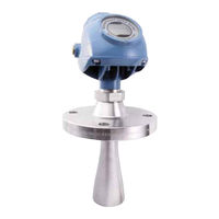
Superior Performance Two-Wire Non-Contacting Radar Level Transmitter
Brand: Emerson
|
Category: Transmitter
|
Size: 4 MB
Table of Contents
Advertisement

Emerson Rosemount 5400 Series Reference Manual (338 pages)
Level Transmitter, Two-Wire Non-Contacting Radar
Brand: Emerson
|
Category: Transmitter
|
Size: 32 MB
Table of Contents

Emerson Rosemount 5400 Series Reference Manual (108 pages)
Brand: Emerson
|
Category: Measuring Instruments
|
Size: 2 MB
Table of Contents
Advertisement

Emerson Rosemount 5400 Series Quick Start Manual (44 pages)
Level Transmitter
Non-Contacting Radar
Brand: Emerson
|
Category: Measuring Instruments
|
Size: 10 MB
Table of Contents

Emerson Rosemount 5400 Series Quick Start Manual (40 pages)
Superior Performance Two-Wire
Non-Contacting Radar Level Transmitter
Brand: Emerson
|
Category: Transmitter
|
Size: 7 MB
Table of Contents

Emerson Rosemount 5400 Series Quick Start Manual (24 pages)
Level Transmitter
Mounting Instructions for Parabolic Antenna
Brand: Emerson
|
Category: Transmitter
|
Size: 11 MB
Table of Contents

Emerson Rosemount 5400 Series Quick Start Manual (20 pages)
Level Transmitter
Brand: Emerson
|
Category: Transmitter
|
Size: 10 MB
Table of Contents
Advertisement
Related Products
- Emerson Rosemount 5408:SIS
- Emerson Rosemount 5081-T
- Emerson Micro Motion 5700
- Emerson 5301HxxxxxxxxxxxxxxZZ Series
- Emerson 5302HxxxxxxxxxxxxxxZZ Series
- Emerson 5303HxxxxxxxxxxxxxxZZ Series
- Emerson Rosemount 5302
- Emerson Rosemount 5303
- Emerson Rosemount Analytical HART SMART 5081C-HT
- Emerson Rosemount 550PT