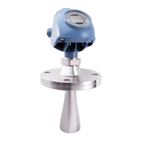
Emerson Rosemount 5400 Quick Start Manual
Level transmitter
non-contacting radar
Hide thumbs
Also See for Rosemount 5400:
- Reference manual (314 pages) ,
- Quick start manual (40 pages) ,
- Quick start manual (20 pages)
Advertisement
Quick Links
See also:
Reference Manual
Advertisement

Related Manuals for Emerson Rosemount 5400


Summary of Contents for Emerson Rosemount 5400
- Page 1 Quick Start Guide 00825-0100-4026, Rev HB June 2017 ™ Rosemount 5400 Level Transmitter Non-Contacting Radar...
-
Page 2: Table Of Contents
Avoid contact with the leads and terminals. High voltage that may be present on leads can cause electrical shock. Make sure the main power to the Rosemount 5400 Level Transmitter is off and the lines to any other external power source are disconnected or not powered while wiring the transmitter. ... -
Page 3: Confirm System Readiness (4-20 Ma Only)
) is loaded on your systems to ensure proper communication. See Table Download the latest device driver from EmersonProcess.com/DeviceFiles. Table 1. Rosemount 5400 Device Revisions and Files Find device driver Firmware version HART universal revision Device revision 2A0 and later 1C0 - 1D0 1. -
Page 4: Mount The Transmitter Head/Antenna
June 2017 Quick Start Guide Mount the transmitter head/antenna Cone antenna with flange Step 1: Lower transmitter with antenna and flange into the nozzle Gasket Step 2: Tighten bolts and nuts Tighten bolts and nuts with sufficient torque for the flange and gasket choice. Step 3: Adjust display orientation (optional) Torque 30 Lbft (40 Nm) - Page 5 Quick Start Guide June 2017 Process seal antenna with flange Step 1: Place antenna on top of the nozzle and mount flange Step 2: Tighten bolts cross-wise For torque information, see table. Process seal flange Torque (Nm) (Lbft) 2 in., 150 lb. 2 in., 300 lb.
- Page 6 June 2017 Quick Start Guide Step 3: Mount transmitter head and tighten nut Torque 30 Lbft (40 Nm) Step 4: Re-tighten flange bolts after 24 hours...
- Page 7 Quick Start Guide June 2017 Rod antenna with threaded connection Step 1: Lower transmitter with antenna into the tank Tank connections with NPT threads require a sealant for pressure-tight joints. Step 2: Turn tank seal adapter until properly secured in the process connection Step 3: Adjust display orientation (optional) Torque...
- Page 8 June 2017 Quick Start Guide Rod antenna with flange Step 1: Lower transmitter with antenna and flange into the nozzle Gasket Step 2: Tighten bolts and nuts Tighten the bolts and nuts with sufficient torque for the flange and gasket choice.
- Page 9 Quick Start Guide June 2017 Tri Clamp tank connection Step 1: Lower transmitter with antenna into the nozzle Gasket Step 2: Fasten Tri Clamp to the tank with a clamp Step 3: Adjust display orientation (optional) Torque 30 Lbft (40 Nm)
- Page 10 June 2017 Quick Start Guide Bracket mounting Step 1: Mount the bracket to the pipe/wall On pipe Horizontal pipe Vertical pipe On wall Use screws suitable for the purpose. Step 2: Mount the transmitter with antenna to the bracket...
-
Page 11: Prepare The Electrical Connections
Figure 1. Wiring Diagram Field Communicator Current meter Load resistance (≥250 Approved IS barrier (for Intrinsically Safe installations only) Power supply HART modem Note Rosemount 5400 Level Transmitters with Flameproof/Explosion-proof output have a built-in barrier; no external barrier needed. - Page 12 June 2017 Quick Start Guide Load limitations For HART communication, a minimum load resistance of 250 is required. Maximum loop resistance is determined by the voltage level of the external power supply, as described by Figure Figure 2. Load Limitations Intrinsically safe installations R(...
- Page 13 Quick Start Guide June 2017 Fieldbus OUNDATION Figure 3. Wiring Diagram Field Communicator Approved IS barrier (for Intrinsically Safe installations only) Fieldbus modem OUNDATION Power supply Note Rosemount 5400 Level Transmitters with Flameproof/Explosion-proof output have a built-in barrier; no external barrier needed.
-
Page 14: Power Consumption
If it is the last transmitter on the bus, connect the 120 termination resistor. HART - HART + Power supply 120 120 RS-485 Bus Note Rosemount 5400 Level Transmitters with Flameproof/Explosion-proof output have a built-in barrier; no external barrier needed. -
Page 15: Connect Wiring And Power Up
Quick Start Guide June 2017 Connect wiring and power up Step 1: Verify that the power supply is disconnected Step 2: Remove the cover Step 3: Remove the plastic plugs Step 4: Pull the cable through the cable gland/conduit Adapters are required if M20 glands are used. Step 5: Connect the cable wires See the wiring diagrams on page... - Page 16 June 2017 Quick Start Guide Step 6: Ensure proper grounding Make sure grounding is done (including IS ground inside Terminal compartment) according to Hazardous Locations Certifications, national and local electrical codes. Transmitter housing grounding The most effective transmitter housing grounding method is a direct connection to earth ground with minimal (<...
- Page 17 Quick Start Guide June 2017 Step 7: Tighten cable glands Apply PTFE tape or other sealant to the threads. Note Arrange the wiring with a drip loop. Step 8: Seal any unused port with enclosed metal plug Apply PTFE tape or other sealant to the threads.
- Page 18 June 2017 Quick Start Guide Step 9: Attach and tighten the cover 1. Verify the cover jam screw is completely threaded into the housing. H2.5 mm Cover jam screw 2. Attach and tighten the cover. The cover must be fully engaged to comply with explosion-proof requirements.
-
Page 19: Configure
Quick Start Guide June 2017 Configure Basic configuration can easily be done either with Rosemount Radar Master, a ™ Field Communicator, the AMS Device Manager, DeltaV , DTM, or any other DD (Device Description) or DTM compatible host system. For advanced configuration features, Rosemount Radar Master is recommended. -
Page 20: Safety Instrumented Systems (4-20 Ma Only)
(enable function) Pipe Inner Diameter TRANSDUCER_1100>ANTENNA_PIPE_DIAM Process Condition TRANSDUCER_1100>ENV_ENVIRONMENT Product Dielectric Constant TRANSDUCER_1100>ENV_DIELECTR_CONST Volume Calculation Method TRANSDUCER_1300>VOLUME_CALC_METHOD Diameter TRANSDUCER_1300>VOL_IDEAL_DIAMETER Length TRANSDUCER_1300>VOL_IDEAL_LENGTH Volume Offset TRANSDUCER_1300>VOL_VOLUME_OFFSET Safety Instrumented Systems (4-20 mA only) For Safety Certified installations, refer to the Rosemount 5400 Reference Manual. -
Page 21: Product Certifications
A copy of the EU Declaration of Conformity can be found at the end of the Quick Start Guide. The most recent revision of the EU Declaration of Conformity can be found at Emerson.com/Rosemount. Ordinary location certification As standard, the transmitter has been examined and tested to determine that... - Page 22 June 2017 Quick Start Guide equipment in Divisions. The markings must be suitable for the area classification, gas, and temperature class. This information is clearly defined in the respective codes. E5 Explosionproof (XP), Dust-Ignitionproof (DIP) Certificate: FM16US0444X Standards: FM Class 3600 – 2011; FM Class 3610 – 2010; FM Class 3611 – 2004; FM Class 3615 –...
- Page 23 Quick Start Guide June 2017 Specific Conditions for Safe Use (X): 1. WARNING – Potential Electrostatic Charging Hazard – The enclosure contains non-metallic material. To prevent the risk for electrostatic sparking the plastic surface should only be cleaned with a damp cloth. 2.
- Page 24 June 2017 Quick Start Guide II 1/2 G Ex db ia IIC T4 Ga/Gb, (-40°C Ta +60°C /+70°C) Markings: II 1 D Ex ta IIIC T69°C/T79°C Da, (-40°C Ta +60°C /+70°C) Um = 250 V Specific Conditions for Safe Use (X): 1.
- Page 25 Quick Start Guide June 2017 shall be indicated on the marking label as specified in the instructions for the transmitter. The antenna part, located in the process vessel, is classified EPL Ga and electrically separated from the “Ex ia” or” ib” circuit. 6.
- Page 26 June 2017 Quick Start Guide N1 ATEX Type N Certificate: Nemko 10ATEX1072X Standards: EN 60079-0:2012, EN 60079-11:2012, EN 60079-15:2010, EN 60079-21:2013 II 3G Ex nA IIC T4 Gc (-50°C Ta +60°C /+70°C) Markings: II 3G Ex ic IIC T4 Gc (-50°C Ta +60°C /+70°C) II 3D Ex tc IIIC T69°C/T79°C Dc (-50°C ...
- Page 27 Quick Start Guide June 2017 electrically separated from the “Ex ia” or” ib” circuit. 6. 1/2” NPT threads need to e sealed for dust and water ingress protection, IP 66, IP 67 or “Ex t”, EPL Da or Db is required. I7 IECEx Intrinsic Safety Certificate: IECEx NEM 06.0001X Standards: IEC 60079-0:2011, IEC 60079-1:2014-06, IEC 60079-11:2011;...
- Page 28 June 2017 Quick Start Guide IG IECEx FISCO Certificate: IECEx NEM 06.0001X Standards: IEC 60079-0:2011, IEC 60079-1:2014-06, IEC 60079-11:2011; IEC 60079-26:2014, IEC 60079-31:2013 Markings: Ex ia IIC T4 Ga (-50°C Ta +60°C) Ex ib IIC T4 Ga/Gb (-50°C Ta +60°C) Ex ia IIIC T69°C/79°C Da (-50°C ...
- Page 29 Quick Start Guide June 2017 42.4 V 23 mA 7.25 nF Negligible Safety parameters HART 32 V 21 mA 0.7 W 4.95 nF Negligible Safety parameters Fieldbus Brazil E2 INMETRO Flameproof Certificate: UL-BR 17.0188X Standards: ABNT NBR IEC 60079-0:2011, ABNT NBR IEC 60079-1:2009 + Errata 1:2011, ABNT NBR IEC 60079-11:2009, ABNT NBR IEC 60079-26:2008 + Errata 1:2009, ABNT NBR IEC 60079-31:2011 Markings: Ex db ia IIC T4 Ga/Gb (- 40°C ...
- Page 30 June 2017 Quick Start Guide 8.10 China E3 China Flameproof Certificate: GYJ16.1094X Standards: GB3836.1/2/4/20-2010, GB12476.1/5-2013, GB12476.4-2010 Markings: Ex d ia IIC T4 Ga/Gb Ex tD A20 IP66/67 T69°C / T79°C Specific Conditions for Safe Use (X): 1. See certificate for Specific Conditions. I3 China Intrinsic Safety Certificate: GYJ16.1094X Standards: GB3836.1/2/4/20-2010, GB12476.1/5-2013, GB12476.4-2010...
- Page 31 Quick Start Guide June 2017 8.11 Technical Regulations Customs Union (EAC) EM Technical Regulations Customs Union (EAC) Flameproof Certificate: RU C-SE.AA87.B.00108 Markings: Ga/Gb Ex d ia IIC T4 X, (-40°C Ta +60°C/+70°C) Specific Conditions for Safe Use (X): 1.
- Page 32 June 2017 Quick Start Guide Specific Conditions for Safe Use (X): 1. See certificate for Specific Conditions. 8.13 India Flameproof Certificate: P392482/1 Markings: Ex db ia T4 Ga/Gb Ex ia T4 Ga Specific Conditions for Safe Use (X): 1. See certificate for Specific Conditions. 8.14 Ukraine Flameproof, Intrinsically Safe...
- Page 33 Quick Start Guide June 2017 Requirements: Bureau Veritas Rules for the Classification of Steel Ships Application: Approval valid for the ships intended to be granted with the following additional class notations: AUT-UMS, AUT-CCS, AUT-PORT and AUT-IMS. SDN Det Norske Veritas (DNV) Type Approval Certificate: A-14117 Intended Use: Det Norske Veritas´...
- Page 34 June 2017 Quick Start Guide ATEX Flameproof and Increased Safety Certificate: FM13ATEX0076X Standards: EN60079-0:2012, EN60079-1:2007, IEC60079-7:2007 Markings: II 2 G Ex de IIC Gb Conduit Plug Thread Sizes Thread Identification mark M20 x 1.5 ½ - 14 NPT ½ NPT Thread Adapter Thread Sizes Male thread Identification mark...
- Page 35 Quick Start Guide June 2017 8.21 EU Declaration of Conformity Figure 7. Rosemount 5400 EU Declaration of Conformity EU Declaration of Conformity No: 5400 Rosemount Tank Radar AB Layoutvägen 1 S-435 33 MÖLNLYCKE Sweden declare under our sole responsibility that the product,...
- Page 36 June 2017 Quick Start Guide Schedule No: 5400 EMC Directive (2014/30/EU) EN 61326-1:2013 ATEX Directive (2014/34/EU) Nemko 04ATEX1073X Intrinsic Safety (Hart@ 4-20mA Equipment Group II, Category 1G, Ex ia IIC T4 Ga Equipment Group II, Category 1/2 G, Ex ib IIC T4 Ga/Gb Equipment Group II, Category 1D, Ex ia IIIC T79°...
- Page 37 Quick Start Guide June 2017 Schedule No: 5400 Nemko 10ATEX1072X Type of protection N, Non-sparking (Hart@ 4-20mA): Equipment Group II, Category 3G, Ex nA IIC T4 Gc Equipment Group II, Category 3D, Ex tc IIIC T79° Dc Type of protection N, Non-sparking (Foundation ® Fieldbus): Equipment Group II, Category 3G, Ex nA IIC T4 Gc Equipment Group II, Category 3D, Ex tc IIIC T69°...
- Page 38 June 2017 Quick Start Guide Schedule No: 5400 ATEX Notified Body for EU Type Examination Certificates and Type Examination Certificates Nemko AS [Notified Body Number: 0470] P.O.Box 73 Blindern 0314 OSLO Norway ATEX Notified Body for Quality Assurance DNV Nemko Presafe AS [Notified Body Number: 2460] Veritasveien 1 1322 HØVIK Norway...
- Page 39 Quick Start Guide June 2017 Figure 8. 9150079-905 - System Control Drawing for Hazardous Location Installation of Intrinsically Safe FM Approved Apparatus...
- Page 40 June 2017 Quick Start Guide Figure 9. 9150079-906 - System Control Drawing for Hazardous Location Installation of CSA Approved Apparatus...
- Page 41 Quick Start Guide June 2017 Figure 10. D9150079-907 - Installation Drawing for Hazardous Location Installation of ATEX and IECEx Approved Apparatus...
- Page 42 June 2017 Quick Start Guide Figure 11. 9240031-958 - Installation Drawing Exn...
- Page 43 Quick Start Guide June 2017 List of Model Parts with China RoHS Concentration above MCVs 含 含 有 管控物 超 的部件型号列表 China RoHS Hazardous Substances / 有害物 Hexavalent Polybrominated Polybrominated Part Name Lead Mercury Cadmium Chromium biphenyls diphenyl ethers 部件名称 汞...
- Page 44 Standard Terms and Conditions of Sale can be found on the Terms Singapore 128461 and Conditions of Sale page. +65 6777 8211 The Emerson logo is a trademark and service mark of Emerson Electric Co. +65 6777 0947 DeltaV, Rosemount, and Rosemount logotype are trademarks of Enquiries@AP.Emerson.com Emerson.
Need help?
Do you have a question about the Rosemount 5400 and is the answer not in the manual?
Questions and answers