Emerson Rosemount 5400 Series Reference Manual
Superior performance two-wire non-contacting radar level transmitter
Hide thumbs
Also See for Rosemount 5400 Series:
- Reference manual (108 pages) ,
- Quick start manual (44 pages) ,
- Quick start manual (24 pages)

Related Manuals for Emerson Rosemount 5400 Series


Summary of Contents for Emerson Rosemount 5400 Series
- Page 1 Reference Manual 00809-0100-4026, Rev HA November 2014 Rosemount 5400 Series Superior Performance Two-Wire Non-Contacting Radar Level Transmitter...
- Page 3 For equipment service or support needs outside the United States, contact your local Emerson Process Management representative. There are no health hazards from the Rosemount 5400 Series transmitter. The microwave power density in the tank is only a small fraction of the allowed power density according to international standards.
- Page 4 Reference Manual November 2014 00809-0100-4026, Rev HA...
-
Page 5: Table Of Contents
Reference Manual Contents 00809-0100-4026, Rev HA November 2014 Contents 1Section 1: Introduction Manual overview ............1 Service support. - Page 6 Reference Manual Contents November 2014 00809-0100-4026, Rev HA 3.4.6 Bracket mounting on wall .........41 3.4.7 Bracket mounting on pipe.
- Page 7 Reference Manual Contents 00809-0100-4026, Rev HA November 2014 5Section 5: Basic Configuration/Start-up Safety messages ............73 Overview .
- Page 8 Reference Manual Contents November 2014 00809-0100-4026, Rev HA 6Section 6: Operation Safety messages ........... . . 119 Viewing measurement data .
- Page 9 Reference Manual Contents 00809-0100-4026, Rev HA November 2014 7.15Troubleshooting ........... . 163 7.15.1Resource block .
- Page 10 Reference Manual Contents November 2014 00809-0100-4026, Rev HA Performance specifications ......... . . 189 A.2.1 General .
- Page 11 Reference Manual Contents 00809-0100-4026, Rev HA November 2014 Approval drawings ........... 230 CAppendix C: Advanced Configuration Tank geometry .
- Page 12 Reference Manual Contents November 2014 00809-0100-4026, Rev HA FAppendix F: Register Transducer Block Overview ............265 F.1.1 Register access transducer block parameters .
-
Page 13: Manual Overview
Safety messages ............page 4 Manual overview The sections in this manual provide installation, configuration, and maintenance information for the Rosemount 5400 Series Radar Level Transmitter. The sections are organized as follows: Section 2: Transmitter Overview Theory of operation „... - Page 14 Reference Manual Section 1: Introduction November 2014 00809-0100-4026, Rev HA Section 5: Basic Configuration/Start-up Configuration instructions „ Configuration using the Rosemount Radar Master (RRM) software „ Configuration using a Field Communicator „ ® Configuration using AMS Suite „ Configuration using DeltaV™ „...
-
Page 15: Service Support
Describes the operation and parameters of the Analog-Input function block „ Service support To expedite the return process outside of the United States, contact the nearest Emerson Process Management representative. Within the United States, call the Emerson Process Management Instrument and Valves Response Center using the 1-800-654-RSMT (7768) toll-free number. -
Page 16: Product Recycling/ Disposal
Reference Manual Section 1: Introduction November 2014 00809-0100-4026, Rev HA Emerson Process Management Instrument and Valves Response Center representatives will explain the additional information and procedures necessary to return goods exposed to hazardous substances. Product recycling/ disposal Recycling of equipment and packaging should be taken into consideration and disposed of in accordance with local and national legislation/regulations. - Page 17 Avoid contact with the leads and terminals. High voltage that may be present on leads „ can cause electrical shock. Make sure the main power to the Rosemount 5400 Series transmitter is off and the „ lines to any other external power source are disconnected or not powered while wiring the transmitter.
- Page 18 Reference Manual Section 1: Introduction November 2014 00809-0100-4026, Rev HA Introduction...
-
Page 19: Theory Of Operation
Antenna selection guide/measuring range ........page 15 Theory of operation The Rosemount 5400 Series Radar Transmitter is a smart, two-wire continuous level transmitter. A 5400 transmitter is installed at the top of the tank and emits short microwave pulses towards the product surface in the tank. -
Page 20: Application Examples
It is easy to mount, maintenance-free, and highly accurate „ Gives precise monitoring and control of the process Overfill and underfill detection The Rosemount 5400 Series can be advantageous in risk reduction systems: Continuous measurement may reduce or simplify proof-tests „... - Page 21 Section 2: Transmitter Overview 00809-0100-4026, Rev HA November 2014 Reactor vessels The innovative design of the Rosemount 5400 Series makes it an excellent choice for the most difficult applications, such as reactor vessels: „ Unique circular polarization provides greater mounting flexibility –...
-
Page 22: System Architecture
November 2014 00809-0100-4026, Rev HA System architecture The Rosemount 5400 Series Radar Transmitter is loop-powered, and uses the same two wires for power supply and output signal. The output is a 4-20 mA analog signal superimposed with a ® ®... - Page 23 Reference Manual Section 2: Transmitter Overview 00809-0100-4026, Rev HA November 2014 Figure 2-3. FOUNDATION fieldbus System Architecture Host / DCS system (e.g. DeltaV) Maintenance OUNDATION fieldbus H2 - High Speed Field Bus H1 - Low Speed Field Bus 6200 ft (1900 m) max (depending upon cable Fieldbus Modem characteristics)
-
Page 24: Process Characteristics
Foam Rosemount 5400 Series Radar Transmitter measurement in foamy applications depends on the foam properties; light and airy or dense and heavy, high or low dielectrics, etc. If the foam is conductive and creamy, the transmitter may measure the surface of the foam. - Page 25 Reference Manual Section 2: Transmitter Overview 00809-0100-4026, Rev HA November 2014 Table 2-1. Sample Solids Applications Common characteristics Particle size Vapor space Dust or Small Larger Steam or Applications Powder (<1 in.) (>1 in.) Dust Condensation Wood chip bins Possible Grain silo - small kernel grains Grain silo - large...
-
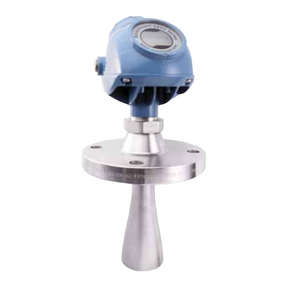
Page 26: Components Of The Transmitter
00809-0100-4026, Rev HA Components of the transmitter The Rosemount 5400 Series Radar Transmitter is available with a die-cast aluminum or stainless steel (SST) housing containing advanced electronics for signal processing. The radar electronics produces an electromagnetic pulse that is emitted through the antenna. -
Page 27: Antenna Selection Guide/Measuring Range
) of the liquid, and process conditions. A higher dielectric constant value produces a stronger reflection. The figures in the tables below are guidelines for optimum performance. Larger measuring ranges may be possible. For more information, contact your local Emerson Process Management representative. - Page 28 Reference Manual Section 2: Transmitter Overview November 2014 00809-0100-4026, Rev HA Table 2-3. Rosemount 5401, Maximum Recommended Measuring Range, ft (m) Frequency Antennas Dielectric Constant 3-in. Cone 82 (25) 115 (35) 115 (35) 4-in. Cone / 23 (7) 39 (12) 49 (15) 82 (25) 115 (35)
- Page 29 (7) Foam can either reflect, be invisible, or absorb the radar signal. Pipe mounting is advantageous since it reduces the foaming tendency. (8) Other wetted material options include Alloy C-276 and Alloy 400. See the Rosemount 5400 Series Product Data Sheet (Document No. 00813-0100-4026) for details.
- Page 30 Reference Manual Section 2: Transmitter Overview November 2014 00809-0100-4026, Rev HA Transmitter Overview...
-
Page 31: Safety Messages
Reference Manual Section 3: Mechanical Installation 00809-0100-4026, Rev HA November 2014 Section 3 Mechanical Installation Safety messages ............page 19 Installation procedure . - Page 32 Avoid contact with the leads and terminals. High voltage that may be present on leads „ can cause electrical shock. Make sure the main power to the Rosemount 5400 Series transmitter is off and the „ lines to any other external power source are disconnected or not powered while wiring the transmitter.
-
Page 33: Installation Procedure
Reference Manual Section 3: Mechanical Installation 00809-0100-4026, Rev HA November 2014 Installation procedure Follow these steps for proper installation: Review installation considerations (see page Mount the transmitter (see page Wire the transmitter (see page Ground the housing (see page Make sure covers and cable/conduit connections are tight Power up the... -
Page 34: Mounting Considerations
Section 3: Mechanical Installation November 2014 00809-0100-4026, Rev HA Mounting considerations Before installing a Rosemount 5400 Series transmitter, consider specific mounting requirements, vessel, and process characteristics. 3.3.1 Mounting location For optimal performance, the transmitter should be installed in locations with a clear and... - Page 35 „ concentrates the radar beam, will be less susceptible to obstruction interference, and assures maximum antenna gain Multiple Rosemount 5400 Series transmitters can be used in the same tank without „ interfering with each other (H) Figure 3-3. Multiple Rosemount 5400 Series Transmitters in the Same Tank...
-
Page 36: Special Considerations In Solids Applications
Reference Manual Section 3: Mechanical Installation November 2014 00809-0100-4026, Rev HA 3.3.2 Special considerations in solids applications The transmitter should be mounted as close to the center of the tank as possible, but „ not in the center of the tank. A general practice is to mount the transmitter at tank radius from the tank wall, see Figure... -
Page 37: Mounting In Pipes
Still-pipe mounting is recommended for tanks with extremely turbulent surface conditions. All cone antenna sizes for the Rosemount 5400 Series of transmitters can be used for Still-pipe installations. The 3 in. (75 mm) antenna for the 5401 is designed for use in Still-pipes only. Rod antennas are not recommended for Still-pipes. -
Page 38: Installation Considerations
PTFE seal in the Rosemount 5400 Series Cone Antennas. An even better solution is to use a Process Seal Antenna if the process pressure permits that. -
Page 39: Nozzle Considerations
The flange on the tank should have a flat or raised face. Other tank flanges may be possible, please consult your local Emerson Process Management representative for advice. Figure 3-10. Nozzle Considerations for 5402 with Process Seal Antenna... - Page 40 Reference Manual Section 3: Mechanical Installation November 2014 00809-0100-4026, Rev HA 5401 with cone antenna The antenna should extend 0.4 in. (10 mm), or more, below the nozzle (L). If required, use the extended cone solution. Figure 3-11. Nozzle Considerations for 5401 with Cone Antenna (L) 0.4 in.
- Page 41 Figure 3-13. Nozzle Considerations for Still-Pipes in Metallic Materials Max. 0.2 in. (5 mm) Ball-valve installation The Rosemount 5400 Series transmitter can be isolated from the process by using a valve: The 5402 is the preferred choice for long nozzle measurement „ Use the largest possible antenna „...
-
Page 42: Nozzle Recommendations And Requirements
00809-0100-4026, Rev HA 3.3.6 Nozzle recommendations and requirements The Rosemount 5400 Series is mounted on a nozzle by using appropriate flanges. For best performance, it is recommended that the nozzle meets the following recommendations for height (L) and diameter: Figure 3-14. Mounting of the Rosemount 5400 Series Transmitter... - Page 43 (2) The extended cone antennas are available in 5 in. (125 mm) step increments from 10 to 50 in. (250-1250 mm). Consult your local Emerson Process Management representative for more information. Expect long lead times for sizes other than the 20 in. (500 mm) version.
-
Page 44: Service Space
Reference Manual Section 3: Mechanical Installation November 2014 00809-0100-4026, Rev HA 3.3.7 Service space For easy access to the transmitter, mount it with sufficient service space. There is no requirement on clearance distance from the tank wall, provided it is flat and free of obstructions such as heating coils and ladders. -
Page 45: Beamwidth
Reference Manual Section 3: Mechanical Installation 00809-0100-4026, Rev HA November 2014 3.3.8 Beamwidth The following recommendations should be considered when mounting the transmitter: The transmitter should be mounted with as few internal structures as possible within „ the beam angle The flat tank wall can be located within the antenna beam angle if there is a minimum „... - Page 46 Reference Manual Section 3: Mechanical Installation November 2014 00809-0100-4026, Rev HA Table 3-6. Beamwidth for the Rosemount 5401 Model (in ft [m]) Antenna Distance 4 in. (DN 100) 6 in. (DN 150) 8 in. (DN 200) cone /rod cone cone 16 ft (5 m) 9.8 (3..0) 6.6 (2.0)
-
Page 47: Vessel Characteristics
3.3.11 Valves The Rosemount 5400 Series transmitter can be isolated from the process by using a valve: Use a full-port ball valve. „ The 5402 is the required and the Process Seal Antenna is the preferred choice, since it „... -
Page 48: Mounting
Reference Manual Section 3: Mechanical Installation November 2014 00809-0100-4026, Rev HA Mounting Mount the transmitter on a nozzle on top of the tank making sure only qualified personnel perform the installation. The transmitter housing must not be opened. If the transmitter housing must be removed for service, make sure the PTFE sealing is carefully protected against dust and water. -
Page 49: Process Seal Antenna
The mounting information applies to the updated Process Seal antenna design, released in February 2012. Antennas manufactured before this date have wetted O-rings and require a different installation procedure. For detailed information on the updated Process Seal antenna, see the Rosemount 5400 Series Reference Manual - Supplementary Information for Process Seal Antennas Manual Supplement (Document No. 00809-0700-4026). -
Page 50: Rod Antenna Threaded Connection
Reference Manual Section 3: Mechanical Installation November 2014 00809-0100-4026, Rev HA Table 3-9. Tightening Torque for Process Seal Flanges Flange Torque (Nm) Torque (Lbft) 2 in. (50 mm), 150 lb. 2 in. (50 mm), 300 lb. 3 in. (75 mm), 150 lb. 3 in. -
Page 51: Rod Antenna Flanged Connection
Reference Manual Section 3: Mechanical Installation 00809-0100-4026, Rev HA November 2014 3.4.4 Rod antenna flanged connection Figure 3-21. Mounting the Rosemount 5400 with Rod Antenna and Flange A. Transmitter housing B. Bolt C. Gasket (optional for the All PFA version) D.Nut E. -
Page 52: Tri-Clamp™ Tank Connection
Reference Manual Section 3: Mechanical Installation November 2014 00809-0100-4026, Rev HA 3.4.5 Tri-Clamp™ tank connection Figure 3-22. Mounting the Rosemount 5400 using a Tri-Clamp A. Nut B. Rod antenna C. Gasket D. Tank connection E. Tri-Clamp F. Clamp Place a gasket on top of the tank flange. Lower the transmitter and antenna into the tank. -
Page 53: Bracket Mounting On Wall
Reference Manual Section 3: Mechanical Installation 00809-0100-4026, Rev HA November 2014 3.4.6 Bracket mounting on wall Figure 3-23. Bracket Mounting the Rosemount 5400, on Wall A. Transmitter housing B. Antenna C. Bracket Mount the bracket directly to the wall with screws suitable for the purpose. Mount the transmitter with antenna to the bracket, then secure the installation with the three supplied screws. -
Page 54: Bracket Mounting On Pipe
Reference Manual Section 3: Mechanical Installation November 2014 00809-0100-4026, Rev HA 3.4.7 Bracket mounting on pipe Figure 3-24. Bracket Mounting the Rosemount 5400, on Pipe A. U-bolts B. Bracket C. Clamping bracket D. Screws E. Transmitter housing F. Screw G. Antenna Put the two U-bolts through the holes of the bracket. -
Page 55: Safety Messages
Reference Manual Section 4: Electrical Installation 00809-0100-4026, Rev HA November 2014 Section 4 Electrical Installation Safety messages ............page 43 Wiring and power supply requirements . -
Page 56: Wiring And Power Supply Requirements
Avoid contact with the leads and terminals. High voltage that may be present on leads „ can cause electrical shock. Make sure the main power to the Rosemount 5400 Series transmitter is off and the „ lines to any other external power source are disconnected or not powered while wiring the transmitter. -
Page 57: Cable/Conduit Entries
For wiring details, refer to pin-out drawing and the cordset manufacturer’s installation instructions. Figure 4-2. Quick Connect Housing Pin-Out “+” “-” Ground No connection For Rosemount 5400 Series transmitters with conduit electrical connector M, refer to the cordset manufacturer’s installation instructions for wiring details. Electrical Installation... -
Page 58: Grounding
Cable selection Use shielded twisted pair wiring for the Rosemount 5400 Series. The cables must be suitable for the supply voltage and approved for use in hazardous areas, where applicable. For instance, in the U.S., explosion-proof conduits must be used in the vicinity of the vessel. For the ATEX flameproof approval version of the Rosemount 5400 Series, suitable conduits with sealing device or flameproof cable glands must be used depending on local requirements. -
Page 59: Hazardous Areas
4.7.1 Connecting the transmitter The Rosemount 5400 Series accepts power supplies ranging from 16 Vdc to 42.4 Vdc. It uses 4-20 mA power superimposed with a HART signal. To connect the transmitter: Verify that the power supply is disconnected. - Page 60 Reference Manual Section 4: Electrical Installation November 2014 00809-0100-4026, Rev HA Figure 4-3. Terminal Compartment and External Ground Screw Terminals for signal Blind plug and power supply Supplied for unused conduit opening. External ground screw Cable entry Cable entry NPT ½ in.-14, NPT ½...
-
Page 61: Hart
4.8.1 Power requirements The Rosemount 5400 Series transmitter operates with a power supply ranging from 16 - 42.4 Vdc (16 - 30 Vdc in IS applications, 20 - 42.4 Vdc in explosion-proof / flameproof applications and in non-sparking / energy-limited applications). - Page 62 + side and if the - side is grounded. Otherwise, the load resistance value is limited to 435 :. Note Rosemount 5400 Series Transmitters with flameproof/explosion-proof output have a built-in barrier; no external barrier needed. Electrical Installation...
-
Page 63: Non-Intrinsically Safe Power Supply
Figure 4-7. Note Make sure the power supply is off when connecting the transmitter. Figure 4-7. Wiring for Non-Intrinsically Safe Power Supply (HART) Rosemount 5400 Series Radar Level Transmitter Power Supply Load Resistance 250 W HART... -
Page 64: Intrinsically Safe Power Supply
Installation also needs to comply with the applicable installation/control drawing. See “Approval drawings” on page 230. Figure 4-8. Wiring Diagram for Intrinsically Safe Power Supply (HART) Rosemount 5400 Series radar level transmitter Power supply =250 W Approved IS barrier... -
Page 65: Type N Approvals: Non-Sparking / Energy-Limited Power Supply
With a non-sparking / energy- limited power supply, wire the transmitter as shown in Figure 4-9. Figure 4-9. Wiring Diagram for Non-Sparking / Energy-Limited Power Supply (HART) Rosemount 5400 Series Radar Level Transmitter Power Supply Load Resistance 250 W... -
Page 66: Transient Protection Terminal Block
Transient protection terminal block For a terminal block with transient protection, wire the transmitter as shown in Figure 4-10. Figure 4-10. Wiring Diagram for Transient Protection Terminal Block (HART) Rosemount 5400 Series Radar Level Transmitter Power Supply Load Resistance 250 W... -
Page 67: Foundation
Explosion-proof/flameproof 16 - 32 None 9 - 32 The Rosemount 5400 Series with F fieldbus operates using a power supply ranging OUNDATION from 9-32 Vdc (9-30 Vdc in IS applications, 16-32 Vdc in explosion-proof / flameproof applications, and 9-17.5 Vdc in FISCO, IS applications). - Page 68 Reference Manual Section 4: Electrical Installation November 2014 00809-0100-4026, Rev HA Connecting fieldbus devices Figure 4-11. Rosemount 5400 Series Radar Transmitter Field Wiring 6200 ft (1900 m) max Integrated power (depending upon cable characteristics) conditioner and filter Terminators fieldbus segment...
-
Page 69: Non-Intrinsically Safe Power Supply
With non-intrinsically safe power supply in Non-hazardous installations or Explo- sion-proof/Flameproof installations, wire the transmitter as shown in Figure 4-12. Rosemount 5400 Series Transmitters with Explosion-proof/Flameproof Output have a built-in barrier; no external barrier needed. Note Make sure that the power supply is off when connecting the transmitter. -
Page 70: Intrinsically Safe Power Supply
Installation also needs to comply with the applicable installation/control drawing. See “Approval drawings” on page 230. Figure 4-13. Wiring Diagram for Intrinsically Safe Power Supply (F fieldbus) OUNDATION Rosemount 5400 Series Power Radar Transmitter supply Approved IS Barrier Fieldbus modem... -
Page 71: Type N Approvals: Non-Sparking / Energy-Limited Power Supply
With a non-sparking / energy-limited power supply, wire the transmitter as shown in Figure 4-14. Figure 4-14. Wiring Diagram for Non-Sparking / Energy-Limited Power Supply (F fieldbus) OUNDATION Rosemount 5400 Series radar level transmitter Power supply Fieldbus modem Field communicator... -
Page 72: Hart To Modbus Converter (Hmc)
4.10 HART to Modbus Converter (HMC) The Rosemount 5400 Series RS-485 with Modbus communication transmitter version operates using a power supply ranging from 8-30 Vdc (max. rating). See the Rosemount 5300/5400 Series with HART to Modbus Converter Manual Supplement (Document No. 00809-0500-4530) for details. - Page 73 Reference Manual Section 4: Electrical Installation 00809-0100-4026, Rev HA November 2014 Figure 4-15. Field Wiring Connections 120W If it is the last transmitter on the bus, connect the 120 W termination resistor verter HART to Modbus Converter MODBUS (RS-485) MODBUS (RS-485) HART POWER...
-
Page 74: 2Connection Terminals
Reference Manual Section 4: Electrical Installation November 2014 00809-0100-4026, Rev HA 4.10.2 Connection terminals The connection terminals are described in Table 4-2 below: Table 4-2. Connection Terminals Connector label Description Comment HART + Positive HART connector Connect to PC with RRM software, Field Communicator, or other HART HART - Negative HART connector... -
Page 75: 3Rs-485 Bus
The RS-485 bus needs to be terminated once at each end, but should not be terminated „ elsewhere on the bus 4.10.4 Installation cases Install the Rosemount 5400 Series Transmitter as shown in Figure 4-17. Use common ground for Modbus Master and Power Supply „... - Page 76 Star topology For a star topology connection of the Rosemount 5400 Series transmitters, the transmitter with the longest cable run needs to be fitted with a 120 : termination resistor. Figure 4-19. Star Topology Connection of Rosemount 5400 Series Transmitters...
-
Page 77: 5External Hart Devices (Slaves)
Reference Manual Section 4: Electrical Installation 00809-0100-4026, Rev HA November 2014 4.10.5 External HART devices (slaves) The HMC supports up to four external HART devices. The external devices are separated by using the HART address. The address must be different between the external devices and only addresses 1 to 5 are allowed for multiple slaves. -
Page 78: Establish Hart Communication
4.11 Establish HART communication The Rosemount 5400 Series can be configured using the RRM PC software or a Field Communicator. Configuration is done by sending HART commands through the HMC to the Rosemount 5400 transmitter electronics. To establish HART communication, connect to the MA/MB terminals, or to the HART terminals. - Page 79 Reference Manual Section 4: Electrical Installation 00809-0100-4026, Rev HA November 2014 Enable HART communication and make sure the port for the RS-485 Converter is selected. Use the following settings: Connect the power wires (or cycle power) to the transmitter. Wait 20 seconds and then open the Search Device window in RRM (also see Note on page 68).
-
Page 80: 2Connect To The Hart Terminals
Reference Manual Section 4: Electrical Installation November 2014 00809-0100-4026, Rev HA Note Take the following into consideration if there are multiple Rosemount 5400 Modbus units on the bus: By default, the transmitters have HART address 1. It will not be possible to establish communication on HART address 1 if several transmitters have the same address. -
Page 81: Optional Devices
Configure Channels 1, 2, and 3 to reflect the units in addition to Upper Range Values and Lower Range Values for secondary, tertiary, and fourth variables (variable assignment is configured in the Rosemount 5400 Series). It is also possible to enable or disable a channel from this menu. Electrical Installation... -
Page 82: 2751 Field Signal Indicator
Section 4: Electrical Installation November 2014 00809-0100-4026, Rev HA 4.12.2 751 Field Signal Indicator Figure 4-23. Wiring Diagram for a Rosemount 5400 Series Transmitter with a 751 Field Signal Indicator 751 Field Signal Rosemount 5400 Series radar transmitter Indicator Power supply... -
Page 83: 3Smart Wireless Thum ™ Adapter
Adapter for Rosemount Process Level Transmitter Applications Technical Note (Document No. 00840-0100-4026) and the Smart Wireless THUM™ Adapter Reference Manual (Document No. 00809-0100-4075). Figure 4-24. Wiring Diagram for a Rosemount 5400 Series with the Smart Wireless THUM Adapter Rosemount Field RRM/Rosemount Communicator Configuration Tool... - Page 84 Reference Manual Section 4: Electrical Installation November 2014 00809-0100-4026, Rev HA Electrical Installation...
-
Page 85: Safety Messages
Reference Manual Section 5: Basic Configuration/Start-up 00809-0100-4026, Rev HA November 2014 Section 5 Basic Configuration/Start-up Safety messages ............page 73 Overview . -
Page 86: 5Section 5: Basic Configuration/Start-Up
Configuration Data Sheet, no further basic configuration is required, unless tank conditions have changed. The Rosemount 5400 Series supports a set of advanced configuration options that can be used to handle special tank conditions and applications. For further information on advanced... -
Page 87: Basic Configuration Parameters
Reference Manual Section 5: Basic Configuration/Start-up 00809-0100-4026, Rev HA November 2014 To communicate with the transmitter using RRM, a HART modem (part number 03300-7004-0001 or 03300-7004-0002) or a F fieldbus modem (part number OUNDATION 03095-5108-0001 for PCMCIA) is required. For F fieldbus communication you will OUNDATION also need the National Instruments Communication Manager software (see... - Page 88 Adapter Upper reference point Tank type and tank bottom type The Rosemount 5400 Series transmitter is optimized according to the Tank Type and Tank Bottom Type configuration by automatically setting some parameters to predefined default values. Select Tank Bottom Type Flat Inclined if the bottom inclination is between 10 and 30 degrees. If the inclination is less than 10 degrees, but there are disturbing objects on the tank floor (like heating coils) within the radar beam, this selection should also be used.
-
Page 89: Process Conditions
Optimize the transmitter for measurement conditions where the level changes quickly from the filling and emptying of the tank. As a default standard, a Rosemount 5400 Series transmitter is able to track level changes of up to 1.5 in./s (40 mm/s). When the Rapid Level Changes check-box is selected, the transmitter can track level changes of up to 8 in./s (200 mm/s). -
Page 90: Volume Configuration
Reference Manual Section 5: Basic Configuration/Start-up November 2014 00809-0100-4026, Rev HA 5.3.4 Volume configuration For volume calculations, choose one of the standard tank shapes or the strapping option. Select None if volume calculation is not used. For the standard tanks, a Volume Offset parameter can be specified which can be used for a non-zero volume that corresponds to the zero level. - Page 91 Reference Manual Section 5: Basic Configuration/Start-up 00809-0100-4026, Rev HA November 2014 Standard tank shapes Figure 5-4. Standard Tank Shapes Vertical cylinder Vertical cylinder tanks are specified by Diameter Height diameter, height, and volume offset. Horizontal cylinder Diameter Horizontal cylinder tanks are specified by diameter, height, and volume offset.
- Page 92 Reference Manual Section 5: Basic Configuration/Start-up November 2014 00809-0100-4026, Rev HA Strapping table The Strapping Table option is used when the tank shape deviates significantly from an ideal sphere or cylinder, or when high volume accuracy is required. The Strapping Table divides the tank into segments. Level values and corresponding volumes are entered at the bottom of the tank.
-
Page 93: Analog Output (Hart)
Reference Manual Section 5: Basic Configuration/Start-up 00809-0100-4026, Rev HA November 2014 5.3.5 Analog output (HART) For the analog output, the output source (primary value), range values, and alarm mode are specified. Figure 5-6. Standard Range Value Settings Upper reference point Transition zone 20 mA Upper Range Value (URV) Product level... -
Page 94: Level And Distance Calibration
Reference Manual Section 5: Basic Configuration/Start-up November 2014 00809-0100-4026, Rev HA Freeze Current: the output current is set to the last valid value at the time when the error occurs. Default settings for alarm mode: Measurement errors: Output current = High „... -
Page 95: Echo Tuning
Echo tuning When Basic Configuration is performed, the transmitter may need to be tuned to handle disturbing objects in the tank. There are different methods available for handling disturbance echoes with the Rosemount 5400 Series Transmitter: „ False echo registration, see “Registration of false echoes”... -
Page 96: Atc
The RRM is a user-friendly software tool that allows configuration of the Rosemount 5400 transmitter. Choose either of the following methods to configure a Rosemount 5400 transmitter with RRM: Guided Setup, if you are unfamiliar with the Rosemount 5400 Series transmitter (see „ page Setup functions, if you are already familiar with the configuration process, or for „... -
Page 97: Help In Rrm
Reference Manual Section 5: Basic Configuration/Start-up 00809-0100-4026, Rev HA November 2014 Software Operating Systems supported: Windows XP „ Windows 7 „ 5.4.2 Help in RRM From the Help menu, select the Contents option to access help information. Help is also available from a Help button in most windows. - Page 98 Reference Manual Section 5: Basic Configuration/Start-up November 2014 00809-0100-4026, Rev HA Getting started From the Start menu, select Programs > Rosemount > Rosemount Radar Master or select the RRM icon in the Windows workspace. If the Search Device window did not appear automatically, select menu option Device > Search.
-
Page 99: Specifying The Com Port
Reference Manual Section 5: Basic Configuration/Start-up 00809-0100-4026, Rev HA November 2014 5.4.4 Specifying the COM port If communication is not established, open the Communication Preferences window and check that the correct COM Port is selected: From the View menu, select Communication Preferences in RRM. Figure 5-9. -
Page 100: To Set The Com Port Buffers
Reference Manual Section 5: Basic Configuration/Start-up November 2014 00809-0100-4026, Rev HA 5.4.5 To set the COM port buffers The COM port Receive Buffer and Transmit Buffer need to be set to 1 by doing the following: ® In the Microsoft Windows Control Panel, open the System option. - Page 101 Reference Manual Section 5: Basic Configuration/Start-up 00809-0100-4026, Rev HA November 2014 Getting started Before starting RRM make sure that appropriate settings are made with the National Instruments Interface Configuration Utility: Use the following settings: Device address = Visitor Device Type = Link Master Device Usage = NI-FBUS Start RRM: from the Start menu click Programs >...
-
Page 102: Specifying Measurement Units
Reference Manual Section 5: Basic Configuration/Start-up November 2014 00809-0100-4026, Rev HA Select the desired transmitter and click OK to connect. In the RRM Status Bar, verify that RRM communicates with the transmitter: RRM communicates with the transmitter No communication with the transmitter 5.4.8 Specifying measurement units Measurement units for data presentation in RRM can be specified when the RRM program is... -
Page 103: Using The Setup Functions
Using the Setup functions Use the Setup function if you are already familiar with the configuration process for the Rosemount 5400 Series transmitter or for changes to the current settings: Figure 5-10. Setup Functions in RRM 1. Start the RRM software. -
Page 104: 10Guided Setup
The following description tells how to use the RRM Guided Setup. The corresponding HART commands (Field Communicator Fast Key Sequence) are also shown. The Guided Setup is useful for those unfamiliar with the Rosemount 5400 Series transmitter. Guided Setup and Configuration Wizard 1. - Page 105 Reference Manual Section 5: Basic Configuration/Start-up 00809-0100-4026, Rev HA November 2014 Device Information 4. The Tag, Message, Descriptor, and Date information is entered in this window. This information is not required for the operation of the transmitter and may be left out, if desired. HART command: [2, 2, 1].
- Page 106 Reference Manual Section 5: Basic Configuration/Start-up November 2014 00809-0100-4026, Rev HA Tank Geometry 6. Select the Tank Type corresponding to the actual tank. If none of the available options matches the tank, select Unknown. HART command: [2, 1, 2, 1]. fieldbus parameter: OUNDATION TRANSDUCER_1100 >...
- Page 107 Reference Manual Section 5: Basic Configuration/Start-up 00809-0100-4026, Rev HA November 2014 Tank Environment 7. In the Process Condition box, select the check-boxes that correspond to the conditions of the tank. Select as few options as possible and no more than two. See “Process conditions”...
- Page 108 Reference Manual Section 5: Basic Configuration/Start-up November 2014 00809-0100-4026, Rev HA Analog output 9. Typically, the Primary Variable (PV) is configured to be Product Level or Volume. Set the analog output range by inputting the Lower Range Value (4 mA) and the Upper Range Value (20 mA) to the desired values.
- Page 109 Reference Manual Section 5: Basic Configuration/Start-up 00809-0100-4026, Rev HA November 2014 Measure and Learn function 12. Select the Yes button to run the Measure and Learn function. If No is selected, this function can be run at a later stage using the Spectrum Analyzer in RRM.
- Page 110 17. When configuration is complete, the configuration should be saved to a backup file. This information is useful for: installing another Rosemount 5400 Series „ transmitter in a similar tank, since the file can be directly uploaded to a new device.
- Page 111 Reference Manual Section 5: Basic Configuration/Start-up 00809-0100-4026, Rev HA November 2014 Guided Setup complete 18. The Guided Setup is now complete. To exit the Guided Setup, select the Close button. Basic Configuration/Start-up...
-
Page 112: 11Using The Setup Functions
Using the Setup functions Use the Setup function if you are already familiar with the configuration process for the Rosemount 5400 Series transmitter or to change the current settings: Figure 5-11. Setup Functions in RRM 1. Start the RRM software. -
Page 113: Configuration Using A Field Communicator
00809-0100-4026, Rev HA November 2014 Configuration using a Field Communicator This section describes the configuration of a Rosemount 5400 Series transmitter with a Field Communicator. The menu tree with the various configuration parameters is shown in Figure 5-14 on page 103. - Page 114 Reference Manual Section 5: Basic Configuration/Start-up November 2014 00809-0100-4026, Rev HA To make a basic setup of the transmitter, do the following: Check that the desired Measurement Units are selected. HART command: [2, 1, 1, 5]. Enter configuration parameters for the following: Device info.
- Page 115 Reference Manual Section 5: Basic Configuration/Start-up 00809-0100-4026, Rev HA November 2014 Figure 5-14. Field Communicator Menu Tree Corresponding to Device Revision 3 Process variables 1 Variable Mapping 1 Primary Variable 2 Geometry 2 2nd 1 Primary Variable 3 Environment 3 3rd 2 2nd 4 Volume 4 4th...
- Page 116 Reference Manual Section 5: Basic Configuration/Start-up November 2014 00809-0100-4026, Rev HA Table 5-4. HART Fast Key Sequences Function HART Fast Key Alarm mode 2, 1, 5, 3 Antenna type 2, 3, 4 Device information 2, 2, 1 LCD language 2, 2, 3 LCD variables 2, 2, 3 Length unit...
-
Page 117: Basic Configuration Using Ams Suite
00809-0100-4026, Rev HA November 2014 Basic configuration using AMS Suite The Rosemount 5400 Series transmitter can be configured using the AMS Suite software: 1. Start the AMS Device Manager making sure the transmitter is connected. The transmitter is displayed in the Device Connection View window (pictures correspond to AMS version 9.0). -
Page 118: Configuration Using Deltav
DeltaV with the AMS application. The corresponding F fieldbus parameters are also OUNDATION shown. The Rosemount 5400 Series supports DD Methods for DeltaV in order to facilitate transmitter configuration. 1. Select DeltaV > Engineering > DeltaV Explorer from the Start menu. - Page 119 Reference Manual Section 5: Basic Configuration/Start-up 00809-0100-4026, Rev HA November 2014 5. Select the Level Measurement setup button. 6. Choose the Tank Type which corresponds to the actual tank. If none of the available options matches the actual tank, choose Unknown. fieldbus parameter: OUNDATION TRANSDUCER_1100 >...
- Page 120 Reference Manual Section 5: Basic Configuration/Start-up November 2014 00809-0100-4026, Rev HA 10. Select the Environment tab. 11. In the Process Conditions box select the check-boxes that correspond to the conditions in your tank. You should select as few options as possible and not more than two. See “Process conditions”...
- Page 121 Reference Manual Section 5: Basic Configuration/Start-up 00809-0100-4026, Rev HA November 2014 12. To configure volume calculation, select the ADV_CONFIG_TB_1300 block and choose the Volume tab. Basic Configuration/Start-up...
- Page 122 Reference Manual Section 5: Basic Configuration/Start-up November 2014 00809-0100-4026, Rev HA 13. Choose a pre-defined calculation method based on a tank shape that corresponds to the actual tank. A. Choose None if volume calculation is not desired. B. Use Volume Offset if you do not want zero volume and zero level to match (for example, if you want to include the product volume below the zero level).
-
Page 123: Advanced Configuration
Reference Manual Section 5: Basic Configuration/Start-up 00809-0100-4026, Rev HA November 2014 5.8.1 Advanced configuration False echo registration In the AMS/DeltaV Explorer select the desired transmitter icon, click the right mouse button and choose the Configure option. Select Manual Setup and choose the Echo Tuning tab. Click the Register False Echo button and follow the wizard to choose and register echoes which can be identified as disturbing objects in the tank. -
Page 124: Foundation
OUNDATION The configuration of a Rosemount 5400 Series transmitter is normally a simple and straightfor- ward task. If the transmitter is pre-configured at the factory according to the ordering specifications in the Configuration Data Sheet, no further Basic Configuration is required unless tank conditions have changed. -
Page 125: Assigning Device Tag And Node Address
5.9.1 Assigning device tag and node address A Rosemount 5400 Series transmitter is shipped with a blank tag and a temporary address (unless specifically ordered with both) to allow a host to automatically assign an address and a tag. If the tag or address need to be changed, use the features of the configuration tool. The tool basically does the following: Changes the address to a temporary address (248-251). - Page 126 Appendix C: Advanced Configuration Transducer Block, Appendix C: Resource Block, and Appendix C: Analog-Input Block. Function blocks The following function blocks are available for the Rosemount 5400 Series: Analog Input (AI) „ Proportional/Integral/Derivative (PID) „ Control Selector (CSEL) „ Output Splitter (OSPL) „...
-
Page 127: Application Examples
Reference Manual Section 5: Basic Configuration/Start-up 00809-0100-4026, Rev HA November 2014 5.10 Application examples 5.10.1 Radar level transmitter - level value Situation A level gauge is measuring the level in a 33 ft (10 m) high tank. Figure 5-17. Situation Diagram 100 % 33 ft (10 m) -
Page 128: 2Radar Level Transmitter - Level Value In Percent (%)
Situation The level of a tank is to be measured using the Rosemount 5400 Series mounted on a nozzle on the top of the tank. The maximum level in the tank is 46 ft (14 m). The level value will be displayed in percentage of the full span (see Figure 5-19). -
Page 129: Tri-Loop™ Hart To Analog Converter
HART burst signal into three additional 4-20 mA analog signals. To set the Rosemount 5400 Series transmitter up for the HART Tri-Loop: Make sure the Rosemount 5400 transmitter is properly configured. Assign transmitter variables Primary Variable, Secondary Variable etc. -
Page 130: Hart Multidrop Configuration
Assign units: Tri-Loop HART command [1, 2, 2, 1, 2]. Make sure that the same units are used as for the Rosemount 5400 Series transmitter. Set the Upper Range Value and the Lower Range Value: Tri-Loop HART command [1, 2, 2, 1, 3-4]. -
Page 131: Safety Messages
Equipment ratings and certifications are no longer valid on any products that have been damaged or modified without the prior written permission of Emerson Process Management. Any continued use of product that has been damaged or modified without prior written authorization is at the customer's sole risk and expense. -
Page 132: Viewing Measurement Data
6.2.1 Using the display panel The Rosemount 5400 Series transmitter uses an optional display panel to present measurement data. When the transmitter is switched on, the display panel presents information, such as transmitter model, measurement frequency, software version, communication type (HART, FF), serial number, HART identification tag, setting of write protection switch, and Analog Output settings. - Page 133 Device Config General Select the LCD tab. Figure 6-2. RRM lets you Specify Variables for the Rosemount 5400 Series Display Panel Select the variables to appear on the Display Panel. The LCD will alternate between the selected items. Click the Store button to save the LCD display settings in the transmitter database.
- Page 134 Reference Manual Section 6: Operation November 2014 00809-0100-4026, Rev HA Using AMS and DeltaV The LCD tab in the Configure window specifies which variables will be shown on the Display Panel screen: Select the transmitter icon in the AMS and DeltaV explorer. Click the right mouse button and choose the Configure option.
- Page 135 Reference Manual Section 6: Operation 00809-0100-4026, Rev HA November 2014 LCD display parameters Table 6-1. LCD Display Parameters and Presentation on Display Presentation on Parameter Description display Level Product level. Distance from the upper reference point to the Distance product surface. Level Rate The speed of level movement up or down.
-
Page 136: Viewing Measurement Data In Rrm
Reference Manual Section 6: Operation November 2014 00809-0100-4026, Rev HA 6.2.3 Viewing measurement data in RRM To view measurements, such as level, signal strength, etc. in RRM, choose the Tools > Device Display option and select the Level tab: Figure 6-4. Presentation of Measurement Data in RRM To view the Analog Output signal, choose the Tools >... -
Page 137: Viewing Measurement Data In Ams Suite And Deltav
Reference Manual Section 6: Operation 00809-0100-4026, Rev HA November 2014 6.2.4 Viewing measurement data in AMS Suite and DeltaV To view measurements, such as level, signal strength, etc. in the AMS Suite: Select the transmitter icon in the AMS Suite Device Connection View window. Click the right mouse button and choose the Overview option. -
Page 138: Lcd Display Error Messages
Section 6: Operation November 2014 00809-0100-4026, Rev HA LCD display error messages Figure 6-7. The Rosemount 5400 Series Display Panel Displaying an Error Message Error message Table 6-2. Error Messages Displayed on the Rosemount 5400 Series Display Panel Error message... -
Page 139: Led Error Messages
00809-0100-4026, Rev HA November 2014 LED error messages For Rosemount 5400 Series transmitters without a display, a flashing Light Emitting Diode (LED) is used to present error messages. Figure 6-8. Rosemount 5400 Series Transmitters without Display use a LED for the... - Page 140 Reference Manual Section 6: Operation November 2014 00809-0100-4026, Rev HA Operation...
-
Page 141: Safety Messages
Reference Manual Section 7: Service and Troubleshooting 00809-0100-4026, Rev HA November 2014 Section 7 Service and Troubleshooting Safety messages ............page 129 Troubleshooting overview . - Page 142 Avoid contact with the leads and terminals. High voltage that may be present on leads „ can cause electrical shock. Make sure the main power to the Rosemount 5400 Series transmitter is off and the „ lines to any other external power source are disconnected or not powered while wiring the transmitter.
-
Page 143: Troubleshooting Overview
(1) A malfunctioning display panel may only be replaced by service personnel at the Emerson Process Management Service Department. (2) If the Rosemount 5400 Series transmitter has been exposed to temperatures outside the specified limits, the device may stop its normal operation. -
Page 144: Service Overview
A missing reference pulse might be a symptom of a malfunctioning transmitter. Contact your local Emerson Process Management representative for assistance. Product surface. This pulse is caused by a reflection on the product surface. -
Page 145: Surface Pulse Not Found
Reference Manual Section 7: Service and Troubleshooting 00809-0100-4026, Rev HA November 2014 The surface thresholds should be set to approximately 20 % of the measured signal amplitude of the product surface. False echo area. False Echo Areas are set during the Measure and Learn function (see “Guided setup”... - Page 146 Reference Manual Section 7: Service and Troubleshooting November 2014 00809-0100-4026, Rev HA Figure 7-3. Example 2: Surface Threshold is Too Low P1 - Disturbing echo Reference misinterpreted as product surface Actual surface Surface threshold = Distance, m By adjusting the surface threshold, the product surface is properly detected, as illustrated in Figure 7-4: Figure 7-4.
-
Page 147: Registration Of False Echoes
The object causes an echo when it is above the surface. When the echoes from the surface and the object are close to each other, they may interfere and cause a decrease in performance. Figure 7-5. The Rosemount 5400 Series can Handle Disturbing Radar Echoes Disturbing objects... - Page 148 Reference Manual Section 7: Service and Troubleshooting November 2014 00809-0100-4026, Rev HA Figure 7-6. Disturbing Echoes can be Filtered Out by Registration as False Echoes Registered false echo Distance, m The False Echo Registration function is available in the RRM program, in the AMS Suite, as well as for the Field Communicator.
-
Page 149: Using The Echo Curve Analyzer
Reference Manual Section 7: Service and Troubleshooting 00809-0100-4026, Rev HA November 2014 7.3.4 Using the Echo Curve Analyzer The Echo Curve in RRM shows the measurement signal amplitude in the tank and includes the Echo Tuning functionality (see “Echo tuning” on page 83 for more information on false echo handling). - Page 150 Reference Manual Section 7: Service and Troubleshooting November 2014 00809-0100-4026, Rev HA The Configuration Mode tab The Configuration Mode tab allows for adjustment of the different amplitude thresholds. When clicking the Echo Curve icon under Device Config/Setup, the Echo Curve Analyzer window appears with the Configuration Mode tab selected: Figure 7-8.
- Page 151 Reference Manual Section 7: Service and Troubleshooting 00809-0100-4026, Rev HA November 2014 The View/Record Mode tab The View/Record Mode tab presents a plot of the current tank conditions where each radar echo is displayed as a peak in the signal plot. When clicking the Echo Curve icon under Device Config/Tools, the Echo Curve Analyzer window appears with the View/Record Mode tab selected: Figure 7-9.
-
Page 152: Using The Echo Curve Analyzer With A Field Communicator
Reference Manual Section 7: Service and Troubleshooting November 2014 00809-0100-4026, Rev HA 7.3.5 Using the Echo Curve Analyzer with a Field Communicator The Field Communicator supports the EDDL with enhancements that allows viewing of the Echo Curve, creating an ATC, and specifying amplitude thresholds, such as the Surface Threshold. Viewing the Echo Curve To view the Echo Curve: Select HART command [2, 5, 2, 3]. - Page 153 Reference Manual Section 7: Service and Troubleshooting 00809-0100-4026, Rev HA November 2014 Register false echoes To register false echoes: Select HART command [2, 5, 1]. Peaks 1 Found Echo Peaks 2 Measurement Output 3 Registered False Echoes 4 Add False Echo... 5 Remove False Echo...
-
Page 154: Analog Output Calibration
Reference Manual Section 7: Service and Troubleshooting November 2014 00809-0100-4026, Rev HA Analog Output calibration This function calibrates the Analog Output by comparing the actual output current with the nominal 4 mA and 20 mA currents. Calibration is done at the factory and normally the transmitter does not need to be recalibrated. -
Page 155: Logging Measurement Data
Reference Manual Section 7: Service and Troubleshooting 00809-0100-4026, Rev HA November 2014 Logging measurement data By using the Log Device Registers function in the RRM software, Input and Holding registers are logged over time. It is possible to choose from different pre-defined sets of registers. This function is useful for verifying that the transmitter is working properly. -
Page 156: Backing Up The Transmitter Configuration
Reference Manual Section 7: Service and Troubleshooting November 2014 00809-0100-4026, Rev HA Backing up the transmitter configuration Use this RRM option to make a backup copy of the configuration parameters in the transmitter database. The backup file can be used to restore the transmitter configuration. It can also be used for configuration of a transmitter in a similar application. -
Page 157: Diagnostics
Reference Manual Section 7: Service and Troubleshooting 00809-0100-4026, Rev HA November 2014 Diagnostics The following information about the device can be retrieved: “Device status” on page 153 „ “Errors” on page 154 „ “Warnings” on page 155 „ “Measurement status” on page 155 „... - Page 158 Reference Manual Section 7: Service and Troubleshooting November 2014 00809-0100-4026, Rev HA AMS and DeltaV To view the Diagnostics window in AMS Suite, click the right mouse button on the desired transmitter and choose the Configure option. Select Service Tools and the tab Active Alerts. Detailed Status is found in Details/Device: Device Service and Troubleshooting...
-
Page 159: Configuration Report
Reference Manual Section 7: Service and Troubleshooting 00809-0100-4026, Rev HA November 2014 Configuration report This RRM function shows the configuration changes made to the transmitter compared to the factory configuration. The report compares a specified backup file with the default transmitter configuration. -
Page 160: Viewing Input And Holding Registers
Reference Manual Section 7: Service and Troubleshooting November 2014 00809-0100-4026, Rev HA Viewing input and holding registers Measured data is continuously stored in the Input Registers and by viewing the contents, advanced users can check if the transmitter is working properly. The Holding Registers store various transmitter parameters, such as configuration data, used to control the measurement performance. -
Page 161: Reset To Factory Settings
Reference Manual Section 7: Service and Troubleshooting 00809-0100-4026, Rev HA November 2014 7.10 Reset to factory settings This function resets all, or a specific part, of the holding registers to the factory settings. It is recommended that a backup of the configuration be made before resetting, so the old transmitter configuration can be loaded, if necessary. -
Page 162: Surface Search
Reference Manual Section 7: Service and Troubleshooting November 2014 00809-0100-4026, Rev HA 7.11 Surface search The Surface Search command triggers a search for the product surface and can be used, for example, if the measured level is locked onto a disturbing object in the tank (see “Configuration report”... -
Page 163: Using The Simulation Mode
Reference Manual Section 7: Service and Troubleshooting 00809-0100-4026, Rev HA November 2014 7.12 Using the Simulation Mode This function can be used to simulate measurements and alarms. RRM: choose menu option Tools > Simulation Mode: AMS Suite: Tools > Service > Simulation Mode. HART Command: [3, 2, 1, 3]. -
Page 164: Write Protecting A Transmitter
7.13 Write protecting a transmitter A Rosemount 5400 Series transmitter can be password protected from unintentional configuration changes. The default password is 12345 and it is recommended that this password not be changed to facilitate service and maintenance of the transmitter. -
Page 165: Diagnostic Messages
“Write protecting a transmitter” on page 152). Set the Write Protection switch to The Write Protection switch is Off. Contact Emerson Process Hardware Write Protected enabled. Management Service Department for information. The transmitter calibration is lost. The factory default configuration is... -
Page 166: 3Errors
Department if the problem database or a hardware error. persists. NOTE: the default values are used until the problem is solved. An error in the microwave module. Contact Emerson Process MWM Error Management Service Department. Contact Emerson Process Display Error An error in the LCD. -
Page 167: 4Warnings
An error in the reference pulse in Check Warning messages. If the last sampled tank signal. MicroWave Module (MWM) Warning is active, this might indicate a transmitter error. Contact Emerson Process Management Service Department. Sweep linearization The sweep is not correctly Check Warning messages. If MWM warning linearized. - Page 168 Action Tank signal clip warning The last Tank Signal was clipped. Check Warning Messages. If MWM Warning is active, this might indicate a transmitter error. Contact Emerson Process Management Service Department. No surface echo The Surface Echo Pulse cannot be Check if the configuration can be detected.
-
Page 169: 6Volume Calculation Status
Reference Manual Section 7: Service and Troubleshooting 00809-0100-4026, Rev HA November 2014 7.14.6 Volume calculation status Volume calculation status messages that may appear on the integral display, on the Field Communicator, or in the RRM program are shown in Table 7-6. -
Page 170: 7Analog Output Status
Communicator or in the RRM program are shown in Table 7-7. Table 7-7. Analog Output Status Message Description Action Analog output hardware is not Contact Emerson Process Not connected connected. Management Service Department. Check “Error Messages” on The analog output is in Alarm page 154 “Warning Messages”... -
Page 171: 8Application Errors
Reference Manual Section 7: Service and Troubleshooting 00809-0100-4026, Rev HA November 2014 7.14.8 Application errors When product surface is May be caused by reduction of near the tank bottom, the projected surface area close to sloping transmitter enters alarm tank bottom. mode (see “Alarm mode”... - Page 172 Reference Manual Section 7: Service and Troubleshooting November 2014 00809-0100-4026, Rev HA Measured value is locked. May be caused by a disturbing object in the tank Action: • Remove the disturbing object • Move the transmitter to another position • Use the Echo Tuning function in RRM to register the false echo causing the transmitter to lock at the wrong level, “Echo tuning”...
- Page 173 Reference Manual Section 7: Service and Troubleshooting 00809-0100-4026, Rev HA November 2014 Incorrect measurement May be caused by: level when the product • Radar echo bouncing from the product surface is above the 50 % surface to the tank roof then back to level.
- Page 174 Reference Manual Section 7: Service and Troubleshooting November 2014 00809-0100-4026, Rev HA The transmitter displays May be caused by: “measurement error” and • Product level within the Hold Off activates Measurement region, that is outside the approved Alarm Alarm when the product measuring range level is close to the Action:...
-
Page 175: Troubleshooting
• Check that the transmitter has not locked on an interfering object. • Check the display configuration; RRM > Setup > General. Integral display does not work • Diagnostics. • Contact Emerson Process Management Service Department • Verify Device Mode setting, should be fieldbus OUNDATION (Parameter: ENV_DEVICE_MODE) -
Page 176: 1Resource Block
SW Error/ Display Error/ Analog Out Error • Call Service Center (1) A malfunctioning display panel may only be replaced by service personnel at the Emerson Process Management Service Department. A display must not be replaced when the transmitter is in operation. -
Page 177: 2Transducer Block
Reference Manual Section 7: Service and Troubleshooting 00809-0100-4026, Rev HA November 2014 Table 7-11. Resource Block DETAILED_STATUS with Recommended Action Messages Condition name Recommended action 1. Restart processor LOI transducer block error 2. Check display connection 3. Call service center 1. - Page 178 Reference Manual Section 7: Service and Troubleshooting November 2014 00809-0100-4026, Rev HA Condition Condition name and description number Input failure/process variable has bad status: The hardware is bad, or a bad status is being simulated Power up Out of service: The actual mode is out of service Table 7-15.
-
Page 179: Safety Messages
Reference Manual Section 8: Safety Instrumented Systems (4-20 mA Only) 00809-0100-4026, Rev HA November 2014 Section 8 Safety Instrumented Systems (4-20 mA Only) Safety messages ............page 167 Overview . -
Page 180: Overview
Overview The following section applies to the 4-20 mA Rosemount 5400 Series with QS Prior-Use Certificate of FMEDA data transmitter used in Safety Instrumented Systems (SIS) applications. The 5400 QS Prior Use option with analog output provides overfill and empty tank protection to improve the system safety. -
Page 181: Skill Level Of Personnel
In the case of the Rosemount 5400 Series, the definition of the Safe State Safety Function is: The distance measurement is performed as intended inside the safety accuracy limits, „... - Page 182 Reference Manual Section 8: Safety Instrumented Systems (4-20 mA Only) November 2014 00809-0100-4026, Rev HA The HART loop must be referenced to ground in one point located between the power supply and the load resistor. Either the negative or the positive pole of the power supply can be ground referenced, depending on the placement of the load resistor.
-
Page 183: Configuration
November 2014 Configuration Use a HART-compliant master, such as RRM or a Field Communicator, to communicate with and verify configuration of the Rosemount 5400 Series. A full review of configuration methods is available in Section 5: Basic Configuration/Start-up. These instructions are applicable to the 5400 QS option with any differences noted. -
Page 184: Amplitude Threshold
8.6.1 General The Rosemount 5400 Series QS option must be tested at regular intervals to confirm that the overfill and empty tank protection function result in the desired system response. The required proof test intervals are dependent on the configuration of the transmitter and the process environment. -
Page 185: Inspection
It is recommended to inspect the antenna for possible build up or clogging. Special tools Not required. Product repair The Rosemount 5400 Series is repairable by major component replacement. All failures detected by the transmitter diagnostics or by the proof test must be reported. Feedback can be submitted electronically at www.emersonprocess.com/rosemount/safety (Contact Us). -
Page 186: References
Section 8: Safety Instrumented Systems (4-20 mA Only) November 2014 00809-0100-4026, Rev HA References 8.7.1 Specifications The Rosemount 5400 Series must be operated in accordance with the functional and performance specifications provided in Appendix A: Reference Data. 8.7.2 Failure rate data The FMEDA report includes failure rates and common cause Beta factor estimates. - Page 187 Reference Manual Section 8: Safety Instrumented Systems (4-20 mA Only) 00809-0100-4026, Rev HA November 2014 Safety Instrumented System – Implementation of one or more Safety Instrumented Functions. A SIS is composed of any combination of sensor(s), logic solver(s), and final element(s). Type B device Complex device (using microcontrollers or programmable logic) Safety Instrumented Systems (4-20 mA Only)
- Page 188 Reference Manual Section 8: Safety Instrumented Systems (4-20 mA Only) November 2014 00809-0100-4026, Rev HA Safety Instrumented Systems (4-20 mA Only)
-
Page 189: Functional Specifications
Reference Manual Appendix A: Reference data 00809-0100-4026, Rev HA November 2014 Appendix A Reference Data Functional specifications ........... . . page 177 Performance specifications . -
Page 190: Ma Hart (Output Option Code H)
Reference Manual Appendix A: Reference data November 2014 00809-0100-4026, Rev HA ® A.1.2 4-20 mA HART (output option code H) Output Two-wire 4–20 mA, HART Revision 5. Digital process variable is superimposed on 4–20 mA signal, and available to any host that conforms to the HART protocol. The HART signal can be used in a multidrop mode. - Page 191 Reference Manual Appendix A: Reference data 00809-0100-4026, Rev HA November 2014 Smart Wireless THUM™ Adapter The optional Smart Wireless THUM adapter can be mounted directly on the transmitter or by ® using a remote mounting kit. IEC 62591 (WirelessHART ) enables access to multi-variable data and diagnostics, and adds wireless to almost any measurement point.
- Page 192 Reference Manual Appendix A: Reference data November 2014 00809-0100-4026, Rev HA Saturation levels Standard: Low=3.9 mA, High=20.8 mA „ Namur NE43: Low = 3.8 mA, High = 20.5 mA „ Figure A-5. Alarm Levels Rosemount alarm level Normal operation 3.75 mA 4 mA 20 mA 21.75 mA...
-
Page 193: Foundation™ Fieldbus (Output Option Code F)
Reference Manual Appendix A: Reference data 00809-0100-4026, Rev HA November 2014 Figure A-8. Explosion-Proof/Flameproof Installations Maximum Load Resistance R( 1400 1200 1148 1000 Operating region 42.4 External Power Supply Voltage U Note The diagram is only valid if the HART load resistance is at the + side and if the - side is grounded, otherwise the load resistance value is limited to 435 :. - Page 194 Reference Manual Appendix A: Reference data November 2014 00809-0100-4026, Rev HA External power supply The input voltage UI for F fieldbus is 9-32 Vdc (9-30 Vdc in IS applications, 9-17.5 Vdc OUNDATION in FISCO applications, and 16-32 Vdc in Explosion-proof / flameproof applications). Quiescent current draw 21 mA fieldbus blocks...
-
Page 195: Rs-485 With Modbus Communication
Reference Manual Appendix A: Reference data 00809-0100-4026, Rev HA November 2014 Figure A-10. Rosemount 2410 Tank Hub Connectivity Rosemount 5400 Level Transmitter TankMaster Field Communication Rosemount 2410 Unit Tank Hub Rosemount 2230 Display Primary bus Tankbus Secondary bus (Non-IS) Secondary bus (IS) Relay Outputs Rosemount 644 Rosemount 2180... - Page 196 Reference Manual Appendix A: Reference data November 2014 00809-0100-4026, Rev HA Figure A-11. RS-485 with Modbus Communication Rosemount 5400 Series Transmitter Power Modbus, Levelmaster Emulation / RS-485 Control system HART modem RS-232 / RS-485 converter 475 Field PC 5400 Setup in...
-
Page 197: Display And Configuration
(see Product Data Sheet, document number OUNDATION 00813-0100-4377). Configuration tools Emerson Field Communicator (e.g. 375/475 Field Communicator), Rosemount Radar Master ® (RRM) software package (included with delivery of transmitter), Emerson AMS Device Manager or any other EDDL or enhanced-EDDL host, or DeltaV™ or any other DD (Device Description) compatible host systems. -
Page 198: Diagnostics
Reference Manual Appendix A: Reference data November 2014 00809-0100-4026, Rev HA Output units Level and distance: ft, in., m, cm, or mm „ Volume: ft , in. , US gals, Imp gals, barrels, yd , or liters „ Level rate: ft/s, m/s „... -
Page 199: Temperature And Pressure Limits
Reference Manual Appendix A: Reference data 00809-0100-4026, Rev HA November 2014 A.1.7 Temperature and pressure limits Ambient temperature Verify that the operating atmosphere of the transmitter is consistent with the appropriate hazardous locations certifications, see Table A-1. Table A-1. Ambient Temperature Ambient temperature IS/Ex ia XP/Ex d... - Page 200 Reference Manual Appendix A: Reference data November 2014 00809-0100-4026, Rev HA Figure A-14. Rosemount 5401 with Rod Antenna (Model Code: 1R-4R) Pressure psig (bar) Rod Antennas 145 (10) Operating range The final rating may be limited by flange and O-ring selection. -14 (-1) Flange temperature °F (°C) -40 (-40)
-
Page 201: Performance Specifications
Reference Manual Appendix A: Reference data 00809-0100-4026, Rev HA November 2014 Flange connection rating Table A-3 for the conditions used for flange strength calculations. Table A-2. Temperature Restrictions due to O-ring Selection (Not Applicable for 1R-2R or 2P-4P Where no Process O-ring is Present) Tank seal with different O-ring Min. -
Page 202: Measuring Range
Due to the measuring range depending on the application and factors described below, the values are a guideline for clean liquids. For more information, ask your local Emerson Process Management representative. Table A-4. Rosemount 5402, Maximum Recommended Measuring Range, ft (m) -
Page 203: Beam Angle And Beam Width
Reference Manual Appendix A: Reference data 00809-0100-4026, Rev HA November 2014 Table A-5. Rosemount 5401, Maximum Recommended Measuring Range, ft (m) Low frequency Dielectric constant antennas 3-in. Cone 82 (25) 115 (35) 115 (35) 4-in. cone / rod 23 (7) 39 (12) 49 (15) 82 (25) - Page 204 Reference Manual Appendix A: Reference data November 2014 00809-0100-4026, Rev HA Table A-6. Beam Angle for the Rosemount 5400 Series Antenna size Beam angle 5402 Beam angle 5401 2-in. Cone / Process Seal 19° 3-in. Cone / Process Seal 14°...
-
Page 205: Transition Zone And Near Zone
Reference Manual Appendix A: Reference data 00809-0100-4026, Rev HA November 2014 A.2.4 Transition zone and near zone Transition zones are areas where measurements are not recommended. Near zones are areas where the accuracy is reduced. Figure A-17. Transition Zone and Near Zone Transition zone Near zone Transition zone... -
Page 206: Environment
Additional deviations at strong electromagnetic fields (NAMUR NE21) at specific frequencies are less than ± 1.6 in. (40 mm). Only a limited selection is presented. Contact your local Emerson Process Management representative for more information. For Japan: “Install device on tanks or pipes made of metal”. -
Page 207: Physical Specifications
A.3.1 Material selection Emerson provides a variety of Rosemount product with various product options and configurations including materials of construction that can be expected to perform well in a wide range of applications. The Rosemount product information presented is intended as a guide for the purchaser to make an appropriate selection for the application. -
Page 208: Engineered Solutions
Reference Manual Appendix A: Reference data November 2014 00809-0100-4026, Rev HA A.3.3 Engineered solutions When standard model codes are not sufficient to fulfill requirements, please consult the factory to explore possible Engineered Solutions. This is typically, but not exclusively, related to the choice of wetted materials or the design of a process connection. - Page 209 Reference Manual Appendix A: Reference data 00809-0100-4026, Rev HA November 2014 Antenna dimensions Cone antenna: See “Rosemount 5402 and 5401 with SST Cone Antenna (Model Code: „ 2S-8S)” on page 200 “Rosemount 5402 and 5401 with Protective Plate Cone Antenna (Model Code: 2H-8H, 2M-8M, and 2N-8N)” on page 201.
- Page 210 SST blind flange (slip-on for Process Seal Antennas) that corresponds to the type and size shown in this table. Find out the weight for the SST blind flange that corresponds to the specific Rosemount 5400 Series flange size which is not represented in this table. The Rosemount 5400 Series flange weight can be estimated by adding the relative weight difference of these SST blind flanges.
- Page 211 Reference Manual Appendix A: Reference data 00809-0100-4026, Rev HA November 2014 Solids applications Rosemount 5402 Non Contacting Radar level transmitter provides industry leading measurement capabilities and reliability on solids. Characteristics include: 4 inch cone antenna (4S, 4H, 4M or 4N) „...
-
Page 212: Dimensional Drawings And Mechanical Properties
(1) The extended cone antennas are available in 5-inch step increments from 10 to 50 inches. Consult your local Emerson Process Management representative for more information. Expect long lead times for other sizes than the 20 in. (500 mm) version. -
Page 213: Rosemount 5402 And 5401 With Protective Plate Cone Antenna (Model Code: 2H-8H, 2M-8M, And 2N-8N)
Reference Manual Appendix A: Reference data 00809-0100-4026, Rev HA November 2014 A.4.2 Rosemount 5402 and 5401 with Protective Plate Cone Antenna (Model Code: 2H-8H, 2M-8M, and 2N-8N) All dimensions are in inches (mm). 7.1 (180) 5.2 (133) 3.5 (88) 3.6 (92) 7.3 (185) 9.4 (240) Protective plate... -
Page 214: Rosemount 5401 With Rod Antenna (Model Code: 1R-4R)
Reference Manual Appendix A: Reference data November 2014 00809-0100-4026, Rev HA A.4.3 Rosemount 5401 with Rod Antenna (Model Code: 1R-4R) All dimensions are in inches (mm). 5.2 (133) 7.1 (180) 3.5 (88) 3.6 (92) 7.3 (185) 9.4 (240) Rod Antenna Rod Antenna with protective without... -
Page 215: Rosemount 5402 With Process Seal Antenna
Reference Manual Appendix A: Reference data 00809-0100-4026, Rev HA November 2014 A.4.4 Rosemount 5402 with Process Seal Antenna (Model Code: 2P-4P) All dimensions are in inches (mm). 7.1 (180) 5.2 (133) 3.5 (88) 3.6 (92) 7.3 (185) 1.1 (27) Process seal size Antenna (in.) code... -
Page 216: Bracket Mounting (Model Code: Br)
Reference Manual Appendix A: Reference data November 2014 00809-0100-4026, Rev HA A.4.5 Bracket mounting (Model Code: BR) Bracket mounting is available for the Rosemount 5401 and 5402 with SST Cone Antenna (2S-8S) and Rosemount 5401 with Rod Antenna (3R-4R). All dimensions are in inches (mm). Pipe diameter max 2.5 inches (64 mm) 5.2 (133) -
Page 217: Process Connections
Reference Manual Appendix A: Reference data 00809-0100-4026, Rev HA November 2014 A.4.6 Process connections Standard flanges Figure A-19. Cone and Rod Antennas (Model Code: 2S-8S and 1R-4R) Designation Mating standard Face style Face surface finish Material ANSI ASME B16.5 0.06 in. raised face = 125-250 ì... -
Page 218: Ordering Information
Reference Manual Appendix A: Reference data November 2014 00809-0100-4026, Rev HA Ordering information Specification and selection of product materials, options, or components must be made by the purchaser of the equipment. See page 195 for more information on Material Selection. Table A-10. - Page 219 Reference Manual Appendix A: Reference data 00809-0100-4026, Rev HA November 2014 Table A-10. 5402 High Frequency Radar Level Transmitter Ordering Information ★ The starred options ( ) represent the most common options and should be selected for best delivery. The non-starred offerings are subject to additional delivery lead time.
- Page 220 Reference Manual Appendix A: Reference data November 2014 00809-0100-4026, Rev HA Table A-10. 5402 High Frequency Radar Level Transmitter Ordering Information ★ The starred options ( ) represent the most common options and should be selected for best delivery. The non-starred offerings are subject to additional delivery lead time.
- Page 221 Reference Manual Appendix A: Reference data 00809-0100-4026, Rev HA November 2014 Table A-10. 5402 High Frequency Radar Level Transmitter Ordering Information ★ The starred options ( ) represent the most common options and should be selected for best delivery. The non-starred offerings are subject to additional delivery lead time.
- Page 222 (12) Requires Protective Plate Cone Antennas (2H-4H, 2M-4M, 2N-4N) or Process Seal Antennas (2P-4P). (13) Only for stainless steel housing material (code S). Not available with Modbus signal output (code M). Contact an Emerson Process Management representative for additional information.
- Page 223 Reference Manual Appendix A: Reference data 00809-0100-4026, Rev HA November 2014 Table A-11. 5401 Low Frequency Radar Level Transmitter Ordering Information ★ The starred options ( ) represent the most common options and should be selected for best delivery. The non-starred offerings are subject to additional delivery lead time.
- Page 224 Reference Manual Appendix A: Reference data November 2014 00809-0100-4026, Rev HA Table A-11. 5401 Low Frequency Radar Level Transmitter Ordering Information ★ The starred options ( ) represent the most common options and should be selected for best delivery. The non-starred offerings are subject to additional delivery lead time.
- Page 225 Reference Manual Appendix A: Reference data 00809-0100-4026, Rev HA November 2014 Table A-11. 5401 Low Frequency Radar Level Transmitter Ordering Information ★ The starred options ( ) represent the most common options and should be selected for best delivery. The non-starred offerings are subject to additional delivery lead time.
- Page 226 Reference Manual Appendix A: Reference data November 2014 00809-0100-4026, Rev HA Table A-11. 5401 Low Frequency Radar Level Transmitter Ordering Information ★ The starred options ( ) represent the most common options and should be selected for best delivery. The non-starred offerings are subject to additional delivery lead time.
- Page 227 (11) Requires Protective Plate Cone Antennas (3H-8H, 3M-8M, 3N-8N) or Rod Antennas (1R-4R). (12) Only available with 4-20 mA HART signal output. (13) Only for stainless steel housing material (code S). Not available with Modbus signal output (code M). Contact an Emerson Process Management representative for additional information.
- Page 228 Reference Manual Appendix A: Reference data November 2014 00809-0100-4026, Rev HA Reference Data...
-
Page 229: Safety Messages
Avoid contact with the leads and terminals. High voltage that may be present on leads „ can cause electrical shock. Make sure the main power to the Rosemount 5400 Series transmitter is off and the „ lines to any other external power source are disconnected or not powered while wiring the transmitter. - Page 230 Emerson Process Management. Any continued use of product that has been damaged or modified without prior written authorization is at the customer's sole risk and expense.
-
Page 231: European Directive Information
équipement. Safety Instrumented Systems (SIS) The Rosemount 5400 Series has been evaluated by a third party, the SP (Technical Research Institute of Sweden), against hardware requirements according to IEC 61508. With a FMEDA (Failure Modes, Effects and Diagnostics Analysis) report with a Safe Failure Fraction (SFF) above 80%, 5400 is suitable in SIS according to the Prior Use methodology. -
Page 232: Hazardous Locations Certifications
177. B.5.1 North-American certifications Factory Mutual (FM) approvals The Rosemount 5400 Series Non-Contacting Radar Level Transmitter that has the following labels attached has been certified to comply with the requirements of the approval agencies noted. Project ID: 3020497 Specific Conditions of Use: WARNING –... -
Page 233: Canadian Standards Association (Csa) Approvals
Reference Manual Appendix B: Product certifications 00809-0100-4026, Rev HA November 2014 B.5.2 Canadian Standards Association (CSA) Approvals When bearing the “Dual Seal” marking, this product meets the Dual Seal Requirements of ANSI/ISA 12.27.01-2003. Cert. No.: 1514653 Explosion-proof with internal Intrinsically safe circuits [Exia] Class I, Div. 1, Groups B, C, and D;... -
Page 234: European Certifications
Reference Manual Appendix B: Product certifications November 2014 00809-0100-4026, Rev HA B.5.3 European certifications ATEX Approvals 0575 Nemko 04ATEX1073X Specific Conditions for Safe Use (X): The intrinsically safe circuits do not withstand the 500V AC test as specified in EN 60079-11clause 6.4.13. “Potential ignition hazards by impact or friction need to be considered according to EN 60079-0:2012 clause 8.3 (for EPL Ga and EPL Gb) and clause 8.4 (for EPL Da and EPL Db), when the transmitter enclosure and antennas exposed to the exterior atmosphere... - Page 235 Reference Manual Appendix B: Product certifications 00809-0100-4026, Rev HA November 2014 Nemko 10ATEX1072 Type n: II 3G Ex nA IIC T4 Gc (-50 °C +70 °C II 3G Ex nL IIC T4 Gc (-50 °C +70 °C HART 4-20 mA Maximum input voltage U : 42.4 V, Maximum input current I : 23 mA...
-
Page 236: Iecex Approval
Reference Manual Appendix B: Product certifications November 2014 00809-0100-4026, Rev HA B.5.4 IECEx Approval IECEx NEM 06.0001X Specific Conditions for Safe Use (X): The intrinsically safe circuits do not withstand the 500V AC test as specified in IEC 60079-11 clause 6.4.13. “Potential ignition hazards by impact or friction need to be considered according to IEC 60079-0:2011 clause 8.3 (for EPL Ga and EPL Gb) and clause 8.4 (for EPL Da and EPL Db), when the transmitter enclosure and antennas exposed to the exterior atmosphere of... -
Page 237: Eac Certifications
Approval valid for HART and Foundation fieldbus options installation drawing 9240031-958 B.5.5 EAC certifications Technical Regulations Customs Union (EAC) EM, IM: Contact an Emerson Process Management representative for additional information. +60 °C with F fieldbus or FISCO option. OUNDATION Valid for Ex nL. -
Page 238: Brazilian Certifications
Reference Manual Appendix B: Product certifications November 2014 00809-0100-4026, Rev HA B.5.6 Brazilian certifications NCC/INMETRO Approvals Special Condition for Safe Use (X): Refer to Certificate NCC 14.2256X Standards ABNT NBR IEC 60079-0:2013, ABNT NBR IEC 60079-1:2009, ABNT NBR IEC 60079-11:2009; ABNT NBR IEC 60079-26:2008, ABNT NBR IEC 60079-27:2010, ABNT NBR IEC 60079-31:2011 Flameproof: Ex ia/db ia IIC T4 Ga/Gb(-40 °C... -
Page 239: Japanese Certifications
Reference Manual Appendix B: Product certifications 00809-0100-4026, Rev HA November 2014 B.5.8 Japanese certifications Technology Institution of Industrial Safety (TIIS) Approval Special Condition for Safe Use (X): Refer to certificate TC20109-TC20111 (4-20 mA HART) and TC20244-TC20246 fieldbus) OUNDATION Flameproof: 4-20 mA HART model: Transmitter: Ex d [ia] IIC T4x +60 °C DC 20 - 42.4 V... -
Page 240: Other Certifications
Reference Manual Appendix B: Product certifications November 2014 00809-0100-4026, Rev HA B.5.9 Other certifications Overfill protection Cert. No: Z-65.16-475 TÜV-tested and approved by DIBt for overfill protection according to the German WHG regulations. Approval valid for HART options. Suitability for Intended Use Compliant with NAMUR NE 95, version 07.07.2006 “Basic Principles of Homologation”. -
Page 241: B.5.10Canadian Registration Number (Crn)
OUNDATION Russian Maritime Register of Shipping Type Approval Certificate Certificate Number: 08.00159.120 Application and limitations: Rosemount 5400 Series Twin-Lead Radar Level Transmitter (models: 5401, 5402) are intended for using on sea-going ships, floating constructions and fixed offshore platforms. Approval valid for HART and F fieldbus options. -
Page 242: Approval Drawings
Installation drawing for hazardous location installation of ATEX and IECEx approved apparatus. Rosemount drawing 9240031-958: „ Installation drawing Ex n Rosemount 5400 Series TIIS drawing TIIS-R-IS 05400-00375: „ Installation drawing for hazardous location installation of TIIS approved apparatus. Product Certifications... -
Page 243: Rev Ha November
Reference Manual Appendix B: Product certifications 00809-0100-4026, Rev HA November 2014 Figure B-1. System Control Drawing for Hazardous Location Installation of Intrinsically Safe FM Approved Apparatus Product Certifications... - Page 244 Reference Manual Appendix B: Product certifications November 2014 00809-0100-4026, Rev HA Figure B-2. System Control Drawing for Hazardous Location Installation of CSA Approved Apparatus Product Certifications...
- Page 245 Reference Manual Appendix B: Product certifications 00809-0100-4026, Rev HA November 2014 Figure B-3. Installation Drawing for Hazardous Location Installation of ATEX and IECEx Approved Apparatus Product Certifications...
- Page 246 Reference Manual Appendix B: Product certifications November 2014 00809-0100-4026, Rev HA Figure B-4. Installation drawing Ex n Rosemount 5400 Series Product Certifications...
- Page 247 Reference Manual Appendix B: Product certifications 00809-0100-4026, Rev HA November 2014 Figure B-5. Installation Drawing for Hazardous Location Installation of TIIS Approved Apparatus (TIIS) 5401/5402 Ex d [ia] IIC T4 X, Ex ia IIC T4 X Uo = 22.2V Io = 177mA Po = 0.985W DC 20~42.4V/4-20mA, DC 16~32V/ Fieldbus AC 250V 50/60Hz, DC250V...
- Page 248 Reference Manual Appendix B: Product certifications November 2014 00809-0100-4026, Rev HA Product Certifications...
-
Page 249: Tank Geometry
Appendix C: Advanced configuration Reference Manual November 2014 00809-0100-4026, Rev HA Appendix C Advanced Configuration Tank geometry ............. page 237 Advanced analog output settings . -
Page 250: Minimum Level Offset (C)
Reference Manual Appendix C: Advanced configuration November 2014 00809-0100-4026, Rev HA C.1.2 Minimum level offset (C) The Minimum Level Offset (C) defines a lower null zone which extends the measurement range beyond the Lower Reference Point to the tank bottom. The Minimum Level Offset is the distance between the Lower Reference Point (Level = 0) and the minimum accepted level at the tank bottom. -
Page 251: Advanced Analog Output Settings
Appendix C: Advanced configuration Reference Manual November 2014 00809-0100-4026, Rev HA Advanced analog output settings The 20 mA Upper Range Value should be outside the Hold Off Distance (see “Hold off distance” on page 238) in order to utilize the full range of the analog output. Figure C-2. - Page 252 Reference Manual Appendix C: Advanced configuration November 2014 00809-0100-4026, Rev HA Empty tank detection area The Empty Tank Detection Area is the range within a lower limit of 16 in. (400 mm) and a higher limit of 39 in. (1000 mm) above the tank bottom. If the surface echo is lost in this region, the tank is considered empty (the device enters Empty Tank State) and the transmitter presents a zero level reading.
-
Page 253: Full Tank Handling
Appendix C: Advanced configuration Reference Manual November 2014 00809-0100-4026, Rev HA C.3.3 Full tank handling Full tank detection area This parameter defines a range where the surface echo can be lost. If the echo is lost in this range, the tank is considered full (the device enters Full Tank State) and the device presents maximum level indication. -
Page 254: Surface Echo Tracking
Reference Manual Appendix C: Advanced configuration November 2014 00809-0100-4026, Rev HA C.3.5 Surface echo tracking Slow search This variable controls how to search for the surface when a surface echo is lost. With this parameter set, the transmitter starts searching for the surface at the last known level and gradually increases the search region until the surface is found. -
Page 255: Filter Settings
Appendix C: Advanced configuration Reference Manual November 2014 00809-0100-4026, Rev HA C.3.6 Filter settings Damping value The Damping Value parameter determines how quickly the transmitter responds to level changes and how robust the measurement signal is against noise. A damping value of 10 indicates that in 10 seconds the output from the transmitter is approximately 63 % of the new level value. - Page 256 Reference Manual Appendix C: Advanced configuration November 2014 00809-0100-4026, Rev HA Amplitude Surface echo Echo from tank bottom Empty tank detection area If the signal from the product surface is lost within the region given by the parameter Empty Tank Detection Area, the tank is considered empty and the product level is presented as zero. If the surface is lost above the Empty Tank Detection Area, the transmitter starts searching the entire tank for the surface.
- Page 257 Appendix C: Advanced configuration Reference Manual November 2014 00809-0100-4026, Rev HA Amplitude If the product surface is lost in this region, the tank is considered empty. “Empty tank detection area” on page 240 for further information. Extra echo function The Extra Echo Detection function makes for more robust measurements in the bottom region for conical or domed bottom shape tanks.
- Page 258 Reference Manual Appendix C: Advanced configuration November 2014 00809-0100-4026, Rev HA Amplitude Advanced Configuration...
-
Page 259: Full Tank Handling
Appendix C: Advanced configuration Reference Manual November 2014 00809-0100-4026, Rev HA C.4.2 Full tank handling With the Full Tank Handling function product levels close to the antenna can be reported as a Full Tank. Normally, measurements are not allowed closer to the antenna than specified by the Hold Off Distance parameter. -
Page 260: Double Bounce
Reference Manual Appendix C: Advanced configuration November 2014 00809-0100-4026, Rev HA C.4.3 Double bounce A double bounce echo is an echo that has been reflected against the tank roof then down to the surface before being detected by the transmitter. Double bounces are commonly present in spherical or horizontal cylinder tanks. -
Page 261: Surface Echo Tracking
Appendix C: Advanced configuration Reference Manual November 2014 00809-0100-4026, Rev HA C.4.4 Surface echo tracking The Surface Echo Tracking function can eliminate ghost echo problems below the product surface. This may occur in Still-pipes because of multiple reflections between the pipe wall, flange, and antenna. -
Page 262: Hold Off Setting
Reference Manual Appendix C: Advanced configuration November 2014 00809-0100-4026, Rev HA C.4.5 Hold off setting The Hold Off parameter is set to a default value that rarely needs any adjustment (see “Hold off distance” on page 238 for definition of Hold Off distance). The Process Seal antenna is slightly more affected by disturbances in the nozzle than the cone and rod antennas. -
Page 263: Performing Proof Test
Appendix D: Performing proof test Reference Manual November 2014 00809-0100-4026, Rev HA Appendix D Performing Proof Test Performing proof test ............page 251 Field communicator . - Page 264 Reference Manual Appendix D: Performing proof test November 2014 00809-0100-4026, Rev HA Figure D-1. Range Values Upper Reference Point Hold Off Distance 20 mA Upper Range Value (URV) Product Level 4 mA Lower Range Value (LRV) Lower Reference Point Min Level Offset (C) (Level=0) Perform a two-point calibration check of the transmitter by applying level at two points within the measuring range.
-
Page 265: Rrm
Appendix D: Performing proof test Reference Manual November 2014 00809-0100-4026, Rev HA Prior to this test, inspect the echo curve to ensure that no disturbing echoes affecting the measurement performance are present. RRM: Tools / Echo Curve Bypass the safety PLC or take other appropriate actions to avoid false trip. Disable write protection if the function is enabled. - Page 266 Reference Manual Appendix D: Performing proof test November 2014 00809-0100-4026, Rev HA Restore the Alarm mode to the original mode used in the loop. Verify that the analog output current is correct. RRM: Set Alarm Mode AOut 1 to original mode. Click Store to save changes. Verify that the output current is correct.
-
Page 267: Ams Suite
Appendix D: Performing proof test Reference Manual November 2014 00809-0100-4026, Rev HA AMS Suite Prior to this test, inspect the echo curve to ensure that no disturbing echoes affecting the measurement performance are present. AMS: Click Configure / Setup / Echo Curve Bypass the safety PLC or take other appropriate actions to avoid false trip. - Page 268 Reference Manual Appendix D: Performing proof test November 2014 00809-0100-4026, Rev HA Click Loop Test... Select Other and enter the mA value representing the high Analog Output Level and follow the instructions. Verify that the output current is correct. Using loop test, enter the mA value representing the low alarm mode. Verify that the analog output current is correct using the reference meter.
-
Page 269: Overview
Diagnostics device errors ........... . . page 264 Overview This section contains information on the Rosemount 5400 Series Transducer Block (TB). Descriptions of all Transducer Block parameters, errors, and diagnostics are listed. -
Page 270: Parameters And Descriptions
Reference Manual Appendix E: Level transducer block November 2014 00809-0100-4026, Rev HA Parameters and descriptions Table E-2. Level Transducer Block Parameters and Descriptions Index Parameter Default value Description number The revision level of the static data associated with the function block. ST_REV The revision value increments each time a static parameter value in the... - Page 271 Appendix E: Level transducer block Reference Manual November 2014 00809-0100-4026, Rev HA Index Parameter Default value Description number The following sub-elements are available: • EU_100 RADAR_LEVEL_RANGE • EU_0 0X03f2(m) • UNITS_INDEX • DECIMAL RADAR_ULLAGE Distance (Ullage) RADAR_LEVELRATE Level Rate The following sub-elements are available: •...
- Page 272 Reference Manual Appendix E: Level transducer block November 2014 00809-0100-4026, Rev HA Index Parameter Default value Description number 0x00000000(0x000000 ENV_ENVIRONMENT Process Condition 0x0c431000(Tank contains double bounces | Slow Search | Show negative level as ENV_PRESENTATION zero | Don’t set invalid Tank Presentation level when empty | Don’t set invalid level...
- Page 273 Appendix E: Level transducer block Reference Manual November 2014 00809-0100-4026, Rev HA Table E-3. Antenna Type VALUE ANTENNA_TYPE User defined Cone 2” Cone 3” Cone 4” Cone 6” Cone 8” Process Seal 2” Process Seal 3” Process Seal 4” Antenna A0 Antenna A1 Antenna A2 Antenna A3...
- Page 274 Reference Manual Appendix E: Level transducer block November 2014 00809-0100-4026, Rev HA Table E-6. Presentation Value of Bit Number DESCRIPTION ENV_PRESENTATION 0x00000001 Reserved 0x00000002 Level above min distance possible 0x00000004 Predicting_Allowed 0x00000008 Bottom echo always visible if tank is empty 0x00000010 Tank contains double bounces 0x00000020...
-
Page 275: Supported Units
Appendix E: Level transducer block Reference Manual November 2014 00809-0100-4026, Rev HA Value of Bit Number DESCRIPTION ENV_PRESENTATION 0x000000200 Bit 8, reserved 0x000000400 Bit 9, reserved 0x000000800 Bit 10, reserved Table E-8. Tank Type VALUE GEOM_TANK_TYPE Unknown Vertical Cylinder Horisontal Cylinder Spherical Cubical Table E-9. -
Page 276: Diagnostics Device Errors
Reference Manual Appendix E: Level transducer block November 2014 00809-0100-4026, Rev HA Table E-12. Level Rate Value Display Description Unit for LCD is the same as set in the value Default window 1061 Meter per second 1063 Meter per hour 1067 Ft/s Feet per second... -
Page 277: Overview
Transducer Block (see Appendix E: Level Transducer Block) it should be handled with care and ONLY to be changed by trained and certified service personnel, or as guided by Emerson Process Management, Rosemount Business Unit support personnel. F.1.1 Register access transducer block parameters Table F-1. - Page 278 Reference Manual Appendix F: Register transducer block November 2014 00809-0100-4026, Rev HA Index Parameter Default value Description number UPDATE_EVT This alert is generated by any change to the static data. The block alarm is used for all configuration, hardware, connection failure, or system problems in the block. The cause of the alert is entered in the subcode field.
- Page 279 Appendix F: Register transducer block Reference Manual November 2014 00809-0100-4026, Rev HA Index Parameter Default value Description number If the register contains a DWORD value and dec is chosen, INP_REG_7_INT_DEC it shall be displayed here INP_REG_8_TYPE Register type If the register contains a float value, it shall be displayed INP_REG_8_FLOAT here If the register contains a DWORD value and dec is chosen,...
- Page 280 Reference Manual Appendix F: Register transducer block November 2014 00809-0100-4026, Rev HA Index Parameter Default value Description number If the register contains a DWORD value and dec is chosen, DB_REG_7_INT_DEC it shall be displayed here DB_REG_8_TYPE Register type If the register contains a float value, it shall be displayed DB_REG_8_FLOAT here If the register contains a DWORD value and dec is chosen,...
-
Page 281: Overview
Overview The Advanced Configuration Transducer Block contains functions for advanced configuration of the Rosemount 5400 Series transmitter. It includes functions such as amplitude threshold settings for filtering of disturbing echoes and noise, simulation of measurement values, and strapping table for volume measurements. - Page 282 Reference Manual Appendix G: Advanced configuration transducer block November 2014 00809-0100-4026, Rev HA Index Parameter Default value Description number XD_ERROR A transducer block alarm subcode. COLLECTION_DIRECTORY TRANSDUCER_TYPE_VER Command. The following sub-elements are available: AMPLITUDE_THRESHOLD_CURVE 0x00000000(Undefined) • ACTION • VALUE Simulation of measurement values. The following sub-elements are available: SIMULATION_MODE 0x00000000...
- Page 283 Appendix G: Advanced configuration transducer block Reference Manual November 2014 00809-0100-4026, Rev HA Index Parameter Default value Description number VOL_STRAP_VOL_8 Strap value volume VOL_STRAP_LEV_9 Strap value level VOL_STRAP_VOL_9 Strap value volume VOL_STRAP_LEV_10 Strap value level VOL_STRAP_VOL_10 Strap value volume VOL_STRAP_LEV_11 Strap value level VOL_STRAP_VOL_11 Strap value volume...
- Page 284 Reference Manual Appendix G: Advanced configuration transducer block November 2014 00809-0100-4026, Rev HA Advanced Configuration Transducer Block...
-
Page 285: Overview
Parameters and descriptions ..........page 273 Overview This section contains information on the Rosemount 5400 Series Radar Level Transmitter Resource Block. Descriptions of all Resource Block Parameters, errors, and diagnostics are included. - Page 286 Reference Manual Appendix H: Resource block November 2014 00809-0100-4026, Rev HA Index Parameter Default value Description number MANUFAC_ID 0x00001151 Manufacturer identification number – used by an interface device to locate the DD file for the resource. DEV_TYPE 5400 Manufacturer’s model number associated with the resource - used by interface devices to locate the DD file for the resource.
- Page 287 Appendix H: Resource block Reference Manual November 2014 00809-0100-4026, Rev HA Index Parameter Default value Description number SHED_ROUT 640000 Time duration at which to give up on computer writes to function block ROut locations. Shed from ROut shall never happen when SHED_ROUT = 0 FAULT_STATE 0x01(Clear) Condition set by loss of communication to an output...
- Page 288 Reference Manual Appendix H: Resource block November 2014 00809-0100-4026, Rev HA Index Parameter Default value Description number FB_OPTIONS 0x00000000 Indicates which function block licensing options are enabled. (0x00000000) DIAG_OPTIONS 0x00000000 Indicates which diagnostics licensing options are enabled. (0x00000000) MISC_OPTIONS 0x00000000 Indicates which miscellaneous licensing options are enabled.
- Page 289 Appendix H: Resource block Reference Manual November 2014 00809-0100-4026, Rev HA Index Parameter Default value Description number SIMULATE_STATE 0x01(Jumper off* no The state of the simulate switch: 0 = Uninitialized simulation) 1 = Switch off, simulation not allowed 2 = Switch on, simulation not allowed (need to cycle jumper/switch) 3 = Switch on, simulation allowed download_mode...
-
Page 290: Plantweb® Alerts
Reference Manual Appendix H: Resource block November 2014 00809-0100-4026, Rev HA Index Parameter Default value Description number ADVISE_MASK 0x00000000 Mask of ADVISE_ALM. Corresponds bit of bit to ADVISE_ACTIVE. A bit on means that the condition is (0x00000000) masked out from alarming. ADVISE_ACTIVE 0x00000000 Enumerated list of advisory conditions within a device. - Page 291 Appendix H: Resource block Reference Manual November 2014 00809-0100-4026, Rev HA FAILED_PRI Designates the alerting priority of the FAILED_ALM, see “Alarm priority” on page 281. The default is 0 and the recommended values are between 8 and 15. FAILED_ACTIVE This parameter displays which of the alarms is active. Only the alarm with the highest priority will be displayed.
- Page 292 Reference Manual Appendix H: Resource block November 2014 00809-0100-4026, Rev HA MAINT_ALM An alarm indicating the device needs maintenance soon. If the condition is ignored, the device will eventually fail. Advisory alarms An advisory alarm indicates informative conditions that do not have a direct impact on the device's primary functions.
-
Page 293: Alarm Priority
Appendix H: Resource block Reference Manual November 2014 00809-0100-4026, Rev HA H.2.2 Alarm priority Alarms are grouped into five levels of priority: Priority Priority description number The alarm condition is not used. An alarm condition with a priority of 1 is recognized by the system, but is not reported to the operator. -
Page 294: Recommended Actions For Plantweb Alerts
Reference Manual Appendix H: Resource block November 2014 00809-0100-4026, Rev HA H.2.3 Recommended actions for PlantWeb alerts RECOMMENDED_ACTION The RECOMMENDED_ACTION parameter displays a text string that will give a recommended course of action to take based on which type and which specific event of the PlantWeb alerts are active. - Page 295 Appendix H: Resource block Reference Manual November 2014 00809-0100-4026, Rev HA Failed/maint/advise/ Alarm type Description Recommended action active event 1. Make sure that enough voltage is The device software has encountered an error. Reasons may be multiple, including supplied to the device. too low supplied voltage, or an error 2.
- Page 296 Reference Manual Appendix H: Resource block November 2014 00809-0100-4026, Rev HA Resource Block...
- Page 297 Appendix I: Analog-Input block Reference Manual November 2014 00809-0100-4026, Rev HA Appendix I Analog-Input Block Simulation ..............page 288 Damping .
- Page 298 Reference Manual Appendix I: Analog-Input block November 2014 00809-0100-4026, Rev HA Index Parameter Units Description number The identification number of the plant unit. This information may be ALERT_KEY None used in the host for sorting alarms, etc. The actual, target, permitted, and normal modes of the block. Target: The mode to “go to”...
- Page 299 Appendix I: Analog-Input block Reference Manual November 2014 00809-0100-4026, Rev HA Index Parameter Units Description number LO_PRI None The priority of the LO alarm. LO_LIM EU of PV_SCALE The setting for the alarm limit used to detect the LO alarm condition. LO_LO_PRI None The priority of the LO LO alarm.
-
Page 300: Simulation
Reference Manual Appendix I: Analog-Input block November 2014 00809-0100-4026, Rev HA Simulation To support testing, you can either change the mode of the block to manual and adjust the output value, or you can enable simulation through the configuration tool and manually enter a value for the measurement value and its status. -
Page 301: Damping
Appendix I: Analog-Input block Reference Manual November 2014 00809-0100-4026, Rev HA Damping The filtering feature changes the response time of the device to smooth variations in output readings caused by rapid changes in input. You can adjust the filter time constant (in seconds) using the PV_FTIME parameter. -
Page 302: Block Errors
Reference Manual Appendix I: Analog-Input block November 2014 00809-0100-4026, Rev HA Block errors Table 2 lists conditions reported in the BLOCK_ERR parameter. Table I-2. BLOCK_ERR Conditions Condition Condition name and description number Other Block configuration error: the selected channel carries a measurement that is incompatible with the engineering units selected in XD_SCALE, the L_TYPE parameter is not configured, or CHANNEL = zero. -
Page 303: Alarm Detection
Appendix I: Analog-Input block Reference Manual November 2014 00809-0100-4026, Rev HA Alarm detection A block alarm will be generated whenever the BLOCK_ERR has an error bit set. The types of block error for the AI block are defined above. Process Alarm detection is based on the OUT value. You can configure the alarm limits of the following standard alarms: High (HI_LIM) „... -
Page 304: Status Handling
Reference Manual Appendix I: Analog-Input block November 2014 00809-0100-4026, Rev HA I.6.1 Status handling Normally, the status of the PV reflects the status of the measurement value, the operating condition of the I/O card, and any active alarm condition. In Auto mode, OUT reflects the value and status quality of the PV. -
Page 305: Configure The Ai Block
Appendix I: Analog-Input block Reference Manual November 2014 00809-0100-4026, Rev HA Configure the AI block A minimum of four parameters are required to configure the AI Block. The parameters are described below with example configurations shown at the end of this section. CHANNEL Select the channel that corresponds to the desired sensor measurement. - Page 306 Reference Manual Appendix I: Analog-Input block November 2014 00809-0100-4026, Rev HA XD_SCALE and OUT_SCALE The XD_SCALE and OUT_SCALE each include three parameters: 0 %, 100 %, and, engineering units. Set these based on the L_TYPE: L_TYPE is direct When the desired output is the measured variable, set the XD_SCALE to represent the operating range of the process.
- Page 307 Appendix I: Analog-Input block Reference Manual November 2014 00809-0100-4026, Rev HA Table I-6. Temperature Display Description °C Degree Celsius °F Degree Fahrenheit Table I-7. Signal Strength Display Description millivolt Table I-8. Volume Display Description Cubic meter Liter Cubic inch Cubic feet Cubic yard Gallon US gallon...
- Page 308 Reference Manual Appendix I: Analog-Input block November 2014 00809-0100-4026, Rev HA Analog-Input Block...
- Page 309 Reference Manual Index 00809-0100-4026, Rev HA November 2014 Index ........117 Burst mode .
- Page 310 Reference Manual Index November 2014 00809-0100-4026, Rev HA ......35 Disturbing objects Installation .
- Page 311 Reference Manual Index 00809-0100-4026, Rev HA November 2014 ........112 .
- Page 312 Reference Manual Index November 2014 00809-0100-4026, Rev HA ......78 Volume Configuration ......80 Strapping Table .
- Page 314 Standard Terms and Conditions of Sale can be found at www.rosemount.com/terms_of_sale Emerson Process Management The Emerson logo is a trademark and service mark of Emerson Electric Co. Latin America AMS, PlantWeb, Rosemount, and the Rosemount logotype are registered trademarks of Rosemount Inc.
Need help?
Do you have a question about the Rosemount 5400 Series and is the answer not in the manual?
Questions and answers