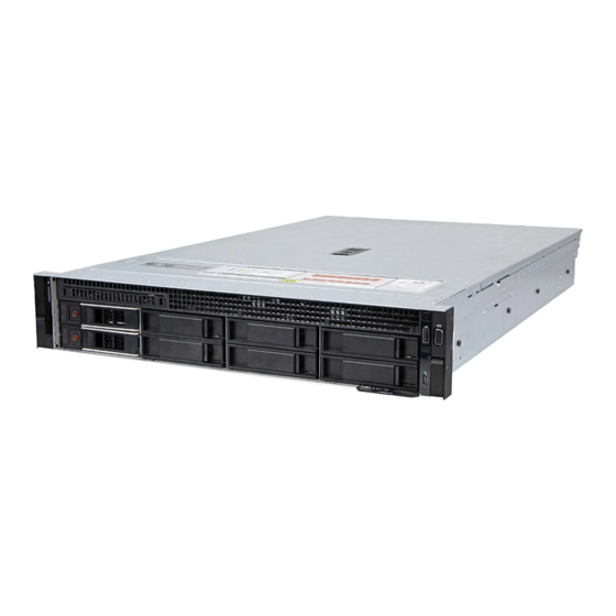
Sign In
Upload
Manuals
Brands
Dell EMC Manuals
Server
PowerEdge R7525
Dell EMC PowerEdge R7525 Manuals
Manuals and User Guides for Dell EMC PowerEdge R7525. We have
2
Dell EMC PowerEdge R7525 manuals available for free PDF download: Installation And Service Manual
Dell EMC PowerEdge R7525 Installation And Service Manual (209 pages)
Brand:
Dell EMC
| Category:
Server
| Size: 52.51 MB
Table of Contents
Table of Contents
2
Figures
7
Tables
11
Chapter 1: About this Document
14
Chapter 2: System Overview
15
Front View of the System
15
Front View of the 24 X 2.5-Inch Drive System
15
Front View of the 16 X 2.5-Inch Drive System
15
Front View of the 8 X 2.5-Inch Drive System
16
Front View of the 12 X 3.5-Inch Drive System
16
Features Available on the Front of the System
16
Left Control Panel
16
Front View of the 8 X 3.5-Inch Drive System
17
Features Available on the Front of the System
17
Left Control Panel View
18
Left Control Panel Without Optional Idrac Quick Sync 2 Indicator
18
Left Control Panel with Optional Idrac Quick Sync 2 Indicator
18
Right Control Panel View
19
Rear View of the System
20
Rear View of the System with 2 X 2.5-Inch Rear Drive Module
21
Inside the System
22
Inside the System with Full Length Risers
23
Locating the Express Service Code and Service Tag
24
System Information Label
24
Service Information
25
Memory Information and System Board Connectors
26
LED Behavior, Configuration and Layout, Express Service Tag for 2.5-Inch HDD System
26
Rail Sizing and Rack Compatibility Matrix
27
LED Behavior, Configuration and Layout, Express Service Tag for 3.5-Inch HDD System
27
Chapter 3: Initial System Setup and Configuration
28
Setting up the System
28
Idrac Configuration
28
Options to Set up Idrac IP Address
28
Interfaces to Set up Idrac IP Address
28
Options to Log in to Idrac
29
Resources to Install Operating System
29
Options to Download Firmware
30
Options to Download and Install os Drivers
30
Resources to Install the Operating System
30
Downloading Drivers and Firmware
31
Chapter 4: Pre-Operating System Management Applications
32
System Setup
32
System Setup Main Menu
32
System BIOS
33
System BIOS Details
33
System Information Details
33
Memory Settings Details
34
Processor Settings Details
34
Processor N Details
35
SATA Settings Details
35
Boot Settings Details
36
UEFI Boot Settings
37
Network Settings Details
38
PXE Device N Settings Details
38
HTTP Device N Settings Details
38
UEFI Iscsi Settings Screen Details
39
ISCSI Device1 Settings Screen Details
39
Integrated Devices Details
39
Serial Communication Details
40
System Profile Settings Details
41
System Security Details
42
Idrac Settings Utility
44
Redundant os Control Details
44
Miscellaneous Settings Details
44
Device Settings
45
Dell Lifecycle Controller
45
Embedded System Management
45
Boot Manager
45
PXE Boot
45
Boot Manager Details
45
Chapter 5: Installing and Removing System Components
46
Safety Instructions
46
Before Working Inside Your System
47
After Working Inside Your System
47
Recommended Tools
47
Optional Front Bezel
48
Removing the Front Bezel
48
Installing the Front Bezel
48
System Cover
49
Removing the System Cover
49
Installing the Front Bezel
49
Installing the System Cover
50
Removing the System Cover
50
Drive Backplane Cover
51
Removing the Drive Backplane Cover
51
Installing the System Cover
51
Installing the Drive Backplane Cover
52
Removing the Drive Backplane Cover
52
Control Panel
53
Removing the Right Control Panel
53
Installing the Drive Backplane Cover
53
Installing the Right Control Panel
54
Removing the Right Control Panel
54
Removing the Left Control Panel
55
Installing the Right Control Panel
55
Installing the Left Control Panel
56
Removing the Left Control Panel
56
Installing the Left Control Panel
57
Air Shroud
58
Removing the Air Shroud
58
Installing the Air Shroud
58
Removing the GPU Air Shroud
59
Installing the Air Shroud
59
Installing the GPU Air Shroud
60
Removing the GPU Air Shroud
60
Removing the GPU Air Shroud Top Cover
61
Installing the GPU Air Shroud
61
Installing the GPU Air Shroud Top Cover
62
Removing the GPU Air Shroud Top Cover
62
Cooling Fan
63
Removing the Cooling Fan Cage Assembly
63
Installing the GPU Air Shroud Top Cover
63
Installing the Cooling Fan Cage Assembly
64
Removing the Cooling Fan Cage Assembly
64
Removing a Cooling Fan
65
Installing the Cooling Fan Cage Assembly
65
Installing a Cooling Fan
66
Removing a Cooling Fan
66
Side Wall Bracket
67
Removing the Side Wall Bracket
67
Installing a Cooling Fan
67
Installing the Side Wall Bracket
68
Removing the Side Wall Bracket
68
Drives
69
Removing a Drive Blank
69
Installing the Side Wall Bracket
69
Installing a Drive Blank
70
Removing the Drive Carrier
70
Removing a Drive Blank
70
Installing the Drive Carrier
71
Removing a Drive Carrier
71
Removing the Drive from the Drive Carrier
72
Installing a Drive Carrier
72
Installing the Drive into the Drive Carrier
73
Removing the Drive from the Drive Carrier
73
Drive Backplane
74
Installing a Drive into the Drive Carrier
74
Supported Backplane Options
74
12X 3.5-Inch Drive Backplane
75
X 3.5-Inch
75
Removing the Drive Backplane
76
Installing the Drive Backplane
77
Removing the Drive Backplane
77
Installing the Drive Backplane
78
Cable Routing
79
12X 3.5-Inch
79
Rear Drive Cage
82
Removing the Rear Drive Cage
82
Installing the Rear Drive Cage
83
Removing the Rear Drive Cage
83
Front PERC Module
84
Removing the Front Mounting Front PERC Module
84
Installing the Rear Drive Cage
84
Installing the Front Mounting Front PERC Module
85
Removing the Front Mounting Front PERC Module
85
Removing the Rear Mounting Front PERC Module
86
Installing the Front Mounting Front PERC Module
86
Installing the Rear Mounting Front PERC Module
87
Removing the Rear Mounting Front PERC Module
87
System Memory
88
System Memory Guidelines
88
Installing the Rear Mounting Front PERC Module
88
General Memory Module Installation Guidelines
89
Memory Channels
89
Supported Memory Matrix
89
Memory Population Rules
90
Supported NPS Modes by Processors
91
Optimal NPS Configuration
91
Removing a Memory Module
92
Installing a Memory Module
93
Removing a Memory Module
93
Processor and Heat Sink
94
Removing a Heat Sink
94
Installing a Memory Module
94
Removing the Processor
95
Removing a Heat Sink
95
Removing Screws on the Force Plate
96
Lifting the Rail Frame
96
Installing the Processor
97
Removing the Processor Tray
97
Placing the Processor Tray into the Rail Frame
98
Closing the Rail Frame
98
Installing the Heat Sink
99
Securing the Force Plate
99
Applying Thermal Grease
100
Expansion Cards and Expansion Card Risers
101
Expansion Card Installation Guidelines
101
Installing the Heat Sink
101
Expansion Card Riser Configurations
101
Configuration 0 - no Riser
102
Configuration 1: R1B
102
Configuration 2: R1B+ R4B
103
Configuration 3: R1A + R2A + R3A + R4A
104
Configuration 6: R1C + R2A + R3A + R4C
106
Configuration 7: R1D + R2A + R3B + R4D
108
Configuration 8: R1A + R2A + R4A
109
Configuration 9: R1B + R2A + R4B
111
Configuration 10: R1B + R2A + R4B
112
Config11:R1D+R2A+R3B+R4B
114
Config12-1: R1D+R2A+R3A+R4A(FL)
122
Removing the Expansion Card Risers
127
Removing the Expansion Card Riser (Riser 1)
128
Removing the Expansion Card Riser (Riser 2)
128
Removing the Expansion Card Riser (Riser 3)
129
Removing the Expansion Card Riser (Riser 4)
129
Installing the Expansion Card Risers
130
Installing the Expansion Card Riser (Riser 1)
130
Installing the Expansion Card Riser (Riser 2)
131
Installing the Expansion Card Riser (Riser 3)
131
Removing Expansion Card from the Expansion Card Riser
132
Installing the Expansion Card Riser (Riser 4)
132
Installing an Expansion Card into the Expansion Card Riser
133
Removing Expansion Card from the Expansion Card Riser
133
Installing the Filler Bracket
133
Removing the Filler Bracket
134
Installing an Expansion Card into the Expansion Card Riser
134
Removing the Full Length Expansion Card Risers
135
Removing the Expansion Card Riser (Riser 1A)
135
Removing the Expansion Card Riser (Riser 3A)
136
Removing the Expansion Card Riser (Riser 4A)
136
Installing the Full Length Expansion Card Risers
137
Installing the Expansion Card Riser (Riser 1A)
137
Installing the Expansion Card Riser (Riser 3A)
138
Installing the Expansion Card Riser (Riser 4A)
138
Removing a GPU
139
Removing the Metal Filler Bracket
139
Installing a GPU
142
Installing the Metal Filler Bracket
142
Optional Serial COM Port
144
Removing the Serial COM Port
144
Removing the Serial COM Port
145
Installing the Serial COM Port
146
Optional IDSDM Module
147
Removing the IDSDM Module
147
Installing the Serial COM Port
147
Installing the IDSDM Module
148
Removing the IDSDM Module
148
Microsd Card
149
Removing the Microsd Card
149
Installing the IDSDM Module
149
Installing the Microsd Card
150
Removing the Microsd Card
150
M.2 SSD Module
151
Removing the M.2 SSD Module
151
Installing the Microsd Card
151
Installing the M.2 SSD Module
152
Removing the M.2 SSD Module
152
System Battery
153
Replacing the System Battery
153
Installing the M.2 SSD Module
153
Removing the System Battery
154
Optional Internal USB Card
155
Removing the Internal USB Card
155
Installing the Internal USB Card
156
Intrusion Switch Module
156
Removing the Intrusion Switch Module
156
Installing the Intrusion Switch Module
157
Removing the Intrusion Switch Module
157
Optional OCP Card
158
Removing the OCP Card
158
Installing the Intrusion Switch Module
158
Removing the OCP Card
159
Installation of Filler Bracket
159
Installing the OCP Card
160
Removal of Filler Bracket
160
Power Supply Unit
161
Hot Spare Feature
161
Installing the OCP Card
161
Removing a Power Supply Unit Blank
162
Installing a Power Supply Unit Blank
162
Removing a Power Supply Unit
162
Installing a Power Supply Unit
163
Removing a Power Supply Unit
163
Trusted Platform Module
164
Upgrading the Trusted Platform Module
164
Installing a Power Supply Unit
164
Initializing TPM for Users
165
Initializing the TPM 1.2 for Users
165
Initializing the TPM 2.0 for Users
165
Installing the TPM
165
System Board
166
Removing the System Board
166
System Board Screw Location
167
Removing the System Board
167
Installing the System Board
168
System Board Screw Location
169
Restoring Service Tag Using Easy Restore
170
LOM Card and Rear I/O Board
170
Removing the LOM Card and Rear I/O Board
170
Installing the LOM Card and Rear I/O Board
171
Removing the LOM Card and Rear I/O Board
171
Installing the LOM Card and Rear I/O Board
172
Chapter 6: Upgrade Kits
173
Upgrade Kits
173
GPU Kit
174
16 X 2.5-Inch
174
GPU Kit Components
174
Cooling Fan and Foam Requirement Matrix
174
Riser and GPU Slot Configuration
175
GPU Power Cable Matrix
175
System Board Jumpers and Connectors
175
Installing Mylar Foam on the System Cover
176
IDSDM Kit
177
IDSDM Port Information
177
Internal USB Card Kit
178
Internal USB Card Port Information
178
Serial COM Port Kit
179
Chapter 7: Jumpers and Connectors
180
System Board Connectors
180
System Board Jumpers and Connectors
180
Right Control Panel
181
System Board Jumper Settings
182
Disabling a Forgotten Password
182
Chapter 8: Technical Specifications
184
Chassis Dimensions
185
Poweredge R7525
185
Chassis Weight
186
Processor Specifications
186
PSU Specifications
186
Poweredge R7525
186
Poweredge R7525 Processor Specifications
186
Poweredge R7525 PSU Specifications
186
Supported Operating Systems
187
Cooling Fan Specifications
187
System Battery Specifications
188
Expansion Card Riser Specifications
188
Expansion Card Slots Supported on the System Board
188
Memory Specifications
189
Storage Controller Specifications
189
Memory Module Sockets
189
Poweredge R7525 System Controller Cards
189
Drive Specifications
190
Drives
190
Ports and Connectors Specifications
190
USB Ports Specifications
190
Poweredge R7525 Front PERC and Adapter PERC Support on Back Planes
190
Poweredge R7525 System USB Specifications
190
NIC Port Specifications
191
Serial Connector Specifications
191
VGA Ports Specifications
191
Idsdm
191
Video Specifications
191
NIC Port Specification
191
Supported SD Card Storage Capacity
191
Supported Front Video Resolution Options
191
Environmental Specifications
192
Supported Rear Video Resolution Options
192
Operational Climatic Range Category A2
192
Operational Climatic Range Category A3
192
Operational Climatic Range Category A4
192
Thermal Air Restrictions
193
Shared Requirements Across All Categories
193
Maximum Vibration Specifications
193
Maximum Shock Pulse Specifications
193
Thermal Restriction Matrix
194
GPU/FPGA Thermal Restriction Matrix
195
Processor and Heat Sink Matrix
195
Label Reference
196
Chapter 9: System Diagnostics and Indicator Codes
197
Status LED Indicators
197
Status LED Indicators and Descriptions
197
System Health and System ID Indicator Codes
198
Idrac Quick Sync 2 Indicator Codes
198
System Health and System ID Indicator
198
Idrac Direct LED Indicator Codes
199
LCD Panel
199
Idrac Quick Sync 2 Indicators and Descriptions
199
Viewing Home Screen
200
Setup Menu
200
LCD Panel Features
200
View Menu
201
NIC Indicator Codes
201
Setup Menu
201
Power Supply Unit Indicator Codes
202
AC PSU Status Indicator
202
AC PSU Status Indicator Codes
202
DC PSU Status Indicator Codes
203
Drive Indicator Codes
204
Using System Diagnostics
204
Dell Embedded System Diagnostics
204
Drive Indicators
204
System Diagnostic Controls
205
Chapter 10: Getting Help
206
Recycling or End-Of-Life Service Information
206
Contacting Dell
206
Accessing System Information by Using QRL
206
Quick Resource Locator for Poweredge R7525 System
207
Receiving Automated Support with Supportassist
207
Chapter 11: Documentation Resources
208
Additional Documentation Resources for Your System
208
Advertisement
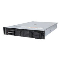
Dell EMC PowerEdge R7525 Installation And Service Manual (187 pages)
Brand:
Dell EMC
| Category:
Server
| Size: 51.14 MB
Table of Contents
Table of Contents
3
Chapter 1: About this Document
7
Chapter 2: System Overview
8
Front View of the System
8
Left Control Panel View
11
Right Control Panel View
12
Rear View of the System
13
Inside the System
16
Locating the Express Service Code and Service Tag
17
System Information Label
18
Rail Sizing and Rack Compatibility Matrix
21
Chapter 3: Initial System Setup and Configuration
22
Setting up the System
22
Idrac Configuration
22
Options to Set up Idrac IP Address
22
Options to Log in to Idrac
23
Resources to Install Operating System
24
Options to Download Firmware
24
Options to Download and Install os Drivers
24
Downloading Drivers and Firmware
25
Chapter 4: Installing and Removing System Components
26
Safety Instructions
26
Before Working Inside Your System
27
After Working Inside Your System
27
Recommended Tools
27
Optional Front Bezel
28
Removing the Front Bezel
28
Installing the Front Bezel
28
System Cover
29
Removing the System Cover
29
Installing the System Cover
30
Drive Backplane Cover
31
Removing the Drive Backplane Cover
31
Installing the Drive Backplane Cover
32
Control Panel
33
Removing the Right Control Panel
33
Installing the Right Control Panel
34
Removing the Left Control Panel
35
Installing the Left Control Panel
36
Air Shroud
38
Removing the Air Shroud
38
Installing the Air Shroud
38
Removing the GPU Air Shroud
39
Installing the GPU Air Shroud
40
Removing the GPU Air Shroud Top Cover
41
Installing the GPU Air Shroud Top Cover
42
Cooling Fan
43
Removing the Cooling Fan Cage Assembly
43
Installing the Cooling Fan Cage Assembly
44
Removing a Cooling Fan
45
Installing a Cooling Fan
46
Side Wall Bracket
47
Removing the Side Wall Bracket
47
Installing the Side Wall Bracket
48
Drives
49
Removing a Drive Blank
49
Installing a Drive Blank
50
Removing the Drive Carrier
50
Installing the Drive Carrier
51
Removing the Drive from the Drive Carrier
52
Installing the Drive into the Drive Carrier
53
Drive Backplane
54
Removing the Drive Backplane
56
Installing the Drive Backplane
57
Cable Routing
59
Rear Drive Cage
64
Removing the Rear Drive Cage
64
Installing the Rear Drive Cage
65
Front PERC Module
66
Removing the Front Mounting Front PERC Module
66
Installing the Front Mounting Front PERC Module
67
Removing the Rear Mounting Front PERC Module
68
Installing the Rear Mounting Front PERC Module
69
System Memory
70
System Memory Guidelines
70
General Memory Module Installation Guidelines
72
Removing a Memory Module
74
Installing a Memory Module
75
Processor and Heat Sink
77
Removing a Heat Sink
77
Removing the Processor
78
Installing the Processor
80
Installing the Heat Sink
82
Expansion Cards and Expansion Card Risers
83
Expansion Card Installation Guidelines
83
Removing the Expansion Card Risers
111
Installing the Expansion Card Risers
114
Removing Expansion Card from the Expansion Card Riser
116
Installing an Expansion Card into the Expansion Card Riser
117
Removing the Full Length Expansion Card Risers
119
Installing the Full Length Expansion Card Risers
121
Removing a GPU
123
Installing a GPU
126
Optional Serial COM Port
128
Removing the Serial COM Port
128
Installing the Serial COM Port
130
Optional IDSDM Module
131
Removing the IDSDM Module
131
Installing the IDSDM Module
132
Microsd Card
133
Removing the Microsd Card
133
Installing the Microsd Card
134
M.2 SSD Module
135
Removing the M.2 SSD Module
135
Installing the M.2 SSD Module
136
BOSS S2 Card (Optional)
137
Removing the BOSS Card Filler
137
Installing the BOSS Card Filler
138
Removing the BOSS S2 Controller Card Module
139
Installing the BOSS S2 Controller Card Module
140
System Battery
142
Replacing the System Battery
142
Optional Internal USB Card
144
Removing the Internal USB Card
144
Installing the Internal USB Card
145
Intrusion Switch Module
146
Removing the Intrusion Switch Module
146
Installing the Intrusion Switch Module
147
Optional OCP Card
148
Removing the OCP Card
148
Installing the OCP Card
150
Power Supply Unit
151
Hot Spare Feature
151
Removing a Power Supply Unit Blank
152
Installing a Power Supply Unit Blank
152
Removing a Power Supply Unit
152
Installing a Power Supply Unit
153
Trusted Platform Module
154
Upgrading the Trusted Platform Module
154
Initializing TPM for Users
155
Initializing the TPM 1.2 for Users
155
Initializing the TPM 2.0 for Users
156
System Board
156
Removing the System Board
156
Installing the System Board
158
Restoring Service Tag Using Easy Restore
160
LOM Card and Rear I/O Board
160
Removing the LOM Card and Rear I/O Board
160
Installing the LOM Card and Rear I/O Board
161
Chapter 5: Upgrade Kits
163
BOSS S2 Kit
163
GPU Kit
166
IDSDM Kit
169
Internal USB Card Kit
170
Serial COM Port Kit
170
Chapter 6: Jumpers and Connectors
171
System Board Connectors
171
System Board Jumper Settings
173
Disabling a Forgotten Password
173
Chapter 7: System Diagnostics and Indicator Codes
175
Status LED Indicators
175
System Health and System ID Indicator Codes
176
Idrac Quick Sync 2 Indicator Codes
176
Idrac Direct LED Indicator Codes
177
LCD Panel
177
Viewing Home Screen
178
Setup Menu
178
View Menu
179
NIC Indicator Codes
179
Power Supply Unit Indicator Codes
180
Drive Indicator Codes
182
Using System Diagnostics
182
Dell Embedded System Diagnostics
182
Chapter 8: Getting Help
184
Recycling or End-Of-Life Service Information
184
Contacting Dell
184
Accessing System Information by Using QRL
184
Quick Resource Locator for Poweredge R7525 System
185
Receiving Automated Support with Supportassist
185
Chapter 9: Documentation Resources
186
Advertisement
Related Products
Dell EMC PowerEdge R7425
Dell EMC PowerEdge R7415
Dell EMC PowerEdge R740
Dell EMC PowerEdge R740xd
Dell EMC PowerEdge R740xd2
Dell EMC PowerEdge R7515
Dell EMC PowerEdge R440
Dell EMC PowerEdge R6415
Dell EMC PowerEdge R6400
Dell EMC PowerEdge R340
Dell EMC Categories
Server
Storage
Laptop
Switch
Network Hardware
More Dell EMC Manuals
Login
Sign In
OR
Sign in with Facebook
Sign in with Google
Upload manual
Upload from disk
Upload from URL