Sign In
Upload
Manuals
Brands
BRUEL & KJAER Manuals
Test Equipment
2032
User Manuals: BRUEL & KJAER 2032 Signal Analyzer
Manuals and User Guides for BRUEL & KJAER 2032 Signal Analyzer. We have
1
BRUEL & KJAER 2032 Signal Analyzer manual available for free PDF download: Instruction Manual
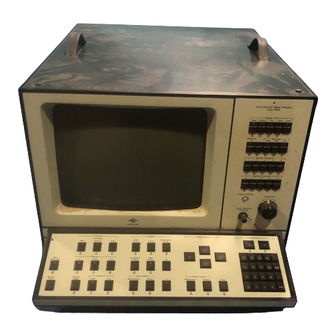
BRUEL & KJAER 2032 Instruction Manual (171 pages)
DUAL CHANNEL SIGNAL ANALYZER
Brand:
BRUEL & KJAER
| Category:
Test Equipment
| Size: 81 MB
Table of Contents
Table of Contents
5
Hard Copy from the 2032 to an X-Y Recorder Type 2308
15
Hard Copy to Other X-Y Recorders
16
1 Introduction and Specifications
19
2 Installation and Grounding Considerations
19
Installation
19
Environment
19
Mounting
19
Connection of a Mains Supply
20
Grounding Considerations
20
3 Operating Principles of the 2032
23
Introduction
23
Measurement Procedure
23
Parameter Entry
24
Use of the FIELD SELECT Controls
24
Use of the FIELD ENTRY Controls
26
The Measurement Setup
28
Storage and Recall of MEASUREMENT SETUPS
29
Definition of the MEASUREMENT SETUP in Use
29
Documentation, Stored, and Working Setups
29
The Display Setup
30
Storage and Recall of DISPLAY SETUPS
31
Using the 2032
32
4 Use of the 2032 Hard Controls
34
Introduction
34
Index to the Front Panel Controls and Connectors of the 2032
34
Index to Rear Panel Controls and Connectors of the 2032
34
Front Panel Controls of the 2032
35
Analog Input and Generator Section
35
Controls Used for Measurement Control
39
Controls Used in the Display of Data
42
Controls Used for Field Select
50
Controls Used for Field Entry
50
Controls Used for Input/Output
51
Controls Used for Special Functions
53
Use of the 2032 Front Panel Controls in Alpha Mode
55
Writing Text into the 2032 Text-String
56
Editing the Text-String
57
Storage and Read-Out of the Text-String
58
Rear Panel Controls and Connectors of the 2032
59
Use of the 2032 Soft Controls
62
Introduction
62
Index to the MEASUREMENT SETUP Control Fields
63
Index to the DISPLAY SETUP Control Fields
63
Index to the CURSOR SETUP Control Fields
63
Index to Other Control Fields
63
Measurement Setup Control Fields
64
Measurement
64
Trigger
65
Delay
66
Averaging
67
Frequency Span
68
Centre Frequency
69
Weighting
70
Input for Ch.a and Ch.b
71
Generator
72
Display Setup Control Fields
73
Function
74
Function Coordinates
75
A-Weighting
76
Y-Scaling
77
X-Scaling
85
Integration/Differentiation
87
Bowtie Correction Field
88
Cursor Setup Control Fields
89
The Cursor Control Field
90
The Main Cursor
91
The Harmonic Cursor
92
The Sideband Cursor
93
The Delta Cursor
94
The Mask Cursor
95
The Reference Cursor
96
The Auxiliary Information Field
96
Other Fields on the 2032 Display
99
Data Source
99
Measurement Setup Reference
101
Shortpass/Longpass Fields
102
Universal Parameter Selector
103
Summary of the Selection Codes for Alphanumeric Fields on the 2032 Display
104
Measurement Setup
104
Display Setup
105
Cursor Setup
105
Other Control Fields
105
6 Calibration of the 2032
106
Calibration of the X-Axis of the 2032
106
Location of Check Marks on the X-Axis
106
Engineering Units Calibration of the X-Axis
108
Calibration of They-Axis of the 2032
109
Calibration of the 2032 to Read in V, V RMS
110
/Hz, or V 2 S/Hz
110
Calibration of the 2032 with the Charge Amplifier Type 2635 to Read in Engineering Units
111
Calibration of the 2032 with the Line-Drive Amplifier Type 2644 to Read in Engineering Units
111
Calibration of the 2032 to Read in Relative Units
112
Calibration of the 2032 to Read in Sound Pressure Level
112
Calibration of the 2032 for Sound Intensity Measurements
113
Influence of Integration and Differentiation on the Calibration of the 2032
114
7 Analog Output from the 2032
115
Hard Copy from the 2032 to an X-Y Recorder
115
Selection of the 2032 X-Y Recorder Output Writing Speed
117
Use of the 2032 Video Output
118
8 Digital 1/0 under Manual Control from the 2032
119
Use of the 2032 with the Graphics Recorder Type 2313
119
Hard Copy from the 2032 to the 2313
119
BZ 7000 and 7006
119
Use of the 2032 with the Digital Cassette Recorder Type 7400
120
Digital Output from the 2032 to the 7400
120
Digital Input from the 7400 to the 2032
120
Recording a Plot File on the 7 400
121
Other Recording Formats on the 7400
121
9 Operating Hints for the 2032
122
Use of Input Autorange
122
Influence of Overloads on Averaging
122
Use of Stored Measurement and Display Setups
123
Mass Storage of User-Defined Measurement and Display Setups
123
Use of Input Low-Pass Fil Teas
123
Selection of Zoom Bandwidth and Centre Frequency
124
Use of Cursors
124
Use of the Field Select Controls
125
Use of the Field Entry Controls
125
Use of System Reset
125
Significance of a Star in a Field
125
Use of Transient and Exponential Windows
126
Triggering the 2032
126
Use of Internal Trigger
126
Use of External Trigger
127
Use of Generator Trigger
128
Use of Manual Trigger
128
Use of Averaging
128
Use of Exponential and Linear Averaging
128
Use of Peak Averaging
128
3: no Overload Reject
145
5: Special Spacer MM
145
6: Noise Bandwidth Ch.a INT
145
7: Noise Bandwidth Ch.a IOE
145
8: Noise Bandwidth Ch.b INT
145
9: Noise Bandwidth Ch.b IOE
145
10: User-Defined Weighting E
146
11: User-Defined Weighting a
146
16: Transient Taper L
146
17: Transient Taper T
146
18: Exponential Taper
146
19: Exponential Delay
146
30: Free Windows
147
Special Parameters, Display
147
40: Frequency Weighting Function
147
41: Frequency Transient Shift, E
147
43: Frequency Transient Taper L, a
148
44: Frequency Transient Taper T, a 2
148
45: Frequency a 3
148
46: Frequency a
148
47: Weighted Frequency Response U
148
48: Weighted Frequency Response L
149
50: Y-Range 2,5/S,Odb
149
60: Lifter Taper
149
70: Graph Update
149
Function Blank
149
72: Correlation Blank
149
73: Phase Blank
149
4: no A-Weighting
150
75: Autospectrum Limit Db
150
76: Weighted Tim~ U
150
77: Weighted Time L
150
78: Littered Cepstrum U
150
79: Littered Cepstrum L
150
Special Parameters, Digital 1/0
151
80: Manual Digital Output
151
81: Manual Digital Output Parameter 1
154
82: Manual Digital Output Parameter 2
154
83: Manual Digital Output Parameter 3
154
84: Repeat Digital Output
154
86: Display 1/0 Status
155
87: CR and Terminator
155
88: Dump-Plot Format
155
Definition of Functions
156
Definition of Symbols
156
Time
156
Frequency
156
Amplitude
157
Advertisement
Advertisement
Related Products
BRUEL & KJAER 2116
BRUEL & KJAER 2010
BRUEL & KJAER 2707
BRUEL & KJAER 2313
BRUEL & KJAER 2031
BRUEL & KJAER 2006
BRUEL & KJAER 2021
BRUEL & KJAER 2033
BRUEL & KJAER 2034
BRUEL & KJAER 2004
BRUEL & KJAER Categories
Measuring Instruments
Test Equipment
Amplifier
Microphone
Analytical Instruments
More BRUEL & KJAER Manuals
Login
Sign In
OR
Sign in with Facebook
Sign in with Google
Upload manual
Upload from disk
Upload from URL