User Manuals: Allied Telesis SwitchBlade x8112 Chassis
Manuals and User Guides for Allied Telesis SwitchBlade x8112 Chassis. We have 3 Allied Telesis SwitchBlade x8112 Chassis manuals available for free PDF download: Installation Manual

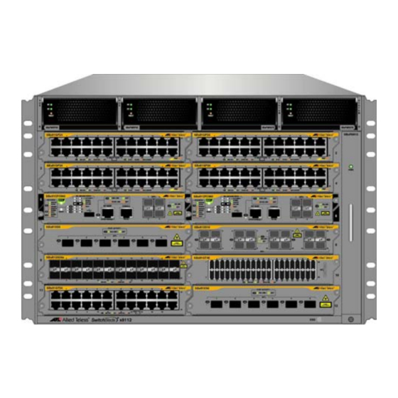
Allied Telesis SwitchBlade x8112 Installation Manual (368 pages)
Layer 3+ Chassis Switch
Brand: Allied Telesis
|
Category: Switch
|
Size: 7 MB
Table of Contents
-
Preface15
-
-
-
Leds39
-
Leds42
-
Leds45
-
Leds47
-
Port Numbers50
-
Leds52
-
Leds55
-
Leds57
-
Leds61
-
Leds62
-
Led64
-
Led66
-
Leds68
-
Speed70
-
Duplex Mode70
-
Port Pinouts71
-
Power Budget74
-
Poe Wiring74
-
-
Guidelines82
-
SFP+ Ports90
-
Net Mgmt Led93
-
USB Port95
-
Reset Button96
-
-
-
-
-
-
-
-
Advertisement
Allied Telesis SwitchBlade x8112 Installation Manual (324 pages)
Brand: Allied Telesis
|
Category: Network Hardware
|
Size: 6 MB
Table of Contents
-
Preface
15 -
-
-
-
Guidelines62
-
SFP+ Slots70
-
USB Port75
-
Reset Button76
-
-
-
-
-
-
-
Allied Telesis SwitchBlade x8112 Installation Manual (280 pages)
Layer 3+ Chassis Switch
Brand: Allied Telesis
|
Category: Network Hardware
|
Size: 6 MB
Table of Contents
-
Preface15
-
-
-
Leds37
-
Leds40
-
Leds43
-
Leds45
-
Leds47
-
Leds49
-
Leds51
-
Led53
-
Led55
-
Leds57
-
Speed58
-
Duplex Mode58
-
Port Pinouts61
-
Power Budget63
-
Poe Wiring63
-
-
Guidelines70
-
Net Mgmt Led79
-
USB Port81
-
Reset Button82
-
-
-
-
-
Advertisement