User Manuals: Allied Telesis x930 Series Layer 3 Switch
Manuals and User Guides for Allied Telesis x930 Series Layer 3 Switch. We have 2 Allied Telesis x930 Series Layer 3 Switch manuals available for free PDF download: Installation Manual

Allied Telesis x930 Series Installation Manual (214 pages)
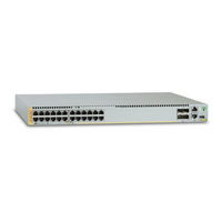
Gigabit Layer 3 Ethernet Switches
Brand: Allied Telesis
|
Category: Switch
|
Size: 7 MB
Table of Contents
-
Preface13
-
-
Models18
-
Features22
-
X930 Models22
-
SFP Ports23
-
Leds24
-
Guidelines29
-
Speed31
-
Duplex Mode31
-
Port Pinouts32
-
Power Budget34
-
SFP Ports38
-
SFP+ Ports39
-
Leds43
-
USB Port51
-
Console Port52
-
-
-
Overview58
-
Stack Trunks59
-
-
-
-
Guidelines104
-
-
-
-
-
Introduction148
-
-
-
Introduction166
-
Command Summary167
-
What to Do Next176
-
-
-
-
Certifications209
Advertisement
Allied Telesis x930 Series Installation Manual (188 pages)
x930 Series Gigabit Layer 3 Ethernet Switches
for VCStack
Brand: Allied Telesis
|
Category: Switch
|
Size: 2 MB
Table of Contents
-
Preface
13 -
-
Models18
-
Features19
-
-
Power Budget35
-
SFP Slots40
-
SFP+ Slots41
-
Leds45
-
USB Port53
-
Console Port54
-
-
-
Overview56
-
-
-
-
-
Guidelines94
-
-
-
-
-
-
-
-
Certifications185
Advertisement
Related Products
- Allied Telesis SwitchBlade x908 Series
- Allied Telesis SWITCH AND SWITCHBLADE X900
- Allied Telesis x900-24 series
- Allied Telesis SwitchBlade x900-12XS
- Allied Telesis x900-48FE-N
- Allied Telesis SwitchBlade x900-24XT
- Allied Telesis SwitchBlade x900-24XT-N
- Allied Telesis SwitchBlade x900-12XT
- Allied Telesis x900-12S
- Allied Telesis AT X900-12XT/S