Allied Telesis SwitchBlade x8112 Installation Manual
Hide thumbs
Also See for SwitchBlade x8112:
- Installation manual (280 pages) ,
- Installation manual (368 pages)
Table of Contents
Advertisement
Quick Links
SwitchBlade x8112
Layer 3+ Chassis Switch
AT-SBx81CFC960
Controller Fabric Card (AlliedWare Plus v5.4.5-1)
AT-SBx8112 Chassis
AT-SBx81GT24 Ethernet Line Card
AT-SBx81GT40 Ethernet Line Card
AT-SBx81GP24 Ethernet PoE Line Card
AT-SBx81GS24a Ethernet SFP Line Card
AT-SBx81XS6 Ethernet SFP+ Line Card
AT-SBx81XS16 Ethernet SFP+ Line Card
AT-SBxPWRSYS1 and AT-SBxPWRSYS2 System Power Supplies
AT-SBxPWRPOE1 PoE Power Supply
Installation Guide
613-001936 Rev. D
Advertisement
Table of Contents
Troubleshooting

Related Manuals for Allied Telesis SwitchBlade x8112


Summary of Contents for Allied Telesis SwitchBlade x8112
-
Page 1: Installation Guide
SwitchBlade x8112 Layer 3+ Chassis Switch AT-SBx81CFC960 Controller Fabric Card (AlliedWare Plus v5.4.5-1) AT-SBx8112 Chassis AT-SBx81GT24 Ethernet Line Card AT-SBx81GT40 Ethernet Line Card AT-SBx81GP24 Ethernet PoE Line Card AT-SBx81GS24a Ethernet SFP Line Card AT-SBx81XS6 Ethernet SFP+ Line Card AT-SBx81XS16 Ethernet SFP+ Line Card... - Page 2 Telesis, Inc. be liable for any incidental, special, indirect, or consequential damages whatsoever, including but not limited to lost profits, arising out of or related to this manual or the information contained herein, even if Allied Telesis, Inc. has been advised of, known, or should have known, the possibility of such damages.
- Page 3 European Union Restriction of the Use of Certain Hazardous Substances (RoHS) in Electrical and Electronic Equipment This Allied Telesis RoHS-compliant product conforms to the European Union Restriction of the Use of Certain Hazardous Substances (RoHS) in Electrical and Electronic Equipment. Allied Telesis ensures RoHS conformance by requiring supplier Declarations of Conformity, monitoring incoming materials, and maintaining manufacturing process controls.
- Page 4 SwitchBlade x8112 Chassis Switch and AT-SBx81CFC960 Card Installation Guide Translated Safety Statements Important: The indicates that a translation of the safety statement is available in a PDF document titled “Translated Safety Statements” on our web site at http://www.alliedtelesis.com/support.
-
Page 5: Table Of Contents
Contents Preface ................................15 Structure of the Installation Guide ........................16 Safety Symbols Used in this Document ......................17 Contacting Allied Telesis ..........................18 Section I: Hardware Overview ................19 Chapter 1: Chassis and Power Supplies .....................21 AT-SBx8112 Chassis ............................22 Slots for the Ethernet Line and Controller Cards....................25 Power Supplies and Power Supply Slots ......................26... - Page 6 Chapter 4: Safety Precautions and Site Requirements ................81 Reviewing Safety Precautions ......................... 82 Selecting a Site for the SwitchBlade x8112 ..................... 86 Installation Tools and Material ......................... 88 Chapter 5: Installing the Chassis in an Equipment Rack ................89 Required Tools and Material ..........................
- Page 7 SwitchBlade x8112 Chassis Switch and AT-SBx81CFC960 Card Installation Guide Installing AT-SP10TW Cables in the AT-SBx81CFC960 Card...............169 Chapter 9: Powering On the Chassis ......................171 Verifying the Installation ..........................172 Powering On AT-SBxPWRSYS1 or AT-SBxPWRSYS2 AC System Power Supplies........173 Powering On AT-SBxPWRPOE1 Power Supplies ..................177 Powering On the AT-SBxPWRSYS1 DC System Power Supply ..............180...
- Page 8 Contents VCStack Plus Feature License ........................280 Optional Feature Licenses ..........................281 Chassis ID Numbers ............................282 Priority Numbers ............................283 Stacking Guidelines ............................285 Chapter 15: Building a Stack ........................287 Before You Begin ............................288 Displaying the Management Software Version Number ................289 Activating the VCStack Plus Feature License....................
- Page 9 Figures Figure 1: AT-SBx8112 Chassis ............................22 Figure 2: Front View of the AT-SBx8112 Chassis ....................... 23 Figure 3: Rear View of the AT-SBx8112 Chassis........................ 24 Figure 4: AT-SBx8112 Chassis with Line Cards, Controller Cards, and Power Supplies ........... 24 Figure 5: Ethernet Line and Controller Cards Slots ......................
- Page 10 List of Figures Figure 50: Inserting the AT-SBxPWRPOE1 Power Supply ....................116 Figure 51: Locking the Handle on the AT-SBxPWRPOE1 Power Supply ................. 117 Figure 52: Removing the Blank Slot Cover from Power Supply Slot C................119 Figure 53: Items Included with the AT-SBxPWRSYS1 DC Power Supply Module............120 Figure 54: On/Off Switch on the AT-SBxPWRSYS1 DC Power Supply ................
- Page 11 SwitchBlade x8112 Chassis Switch and AT-SBx81CFC960 Card Installation Guide Figure 108: Connecting the AC Power Cord for the AT-SBxPWRPOE1 Power Supply............ 177 Figure 109: Securing the Power Cord for the AT-SBxPWRPOE1 Power Supply to an Anchor ........178 Figure 110: Dress and Secure AC Power Cords ....................... 179 Figure 111: Components of the AT-SBxPWRSYS1 DC Power Supply................
- Page 12 List of Figures Figure 168: Cabling the SFP+ Slots When Both Switches have One Controller Card ............277 Figure 169: Cabling the SFP+ Slots When Both Switches have Two Controller Cards ............ 278 Figure 170: Chassis ID Number in the Numbering Format....................282 Figure 171: SHOW SYSTEM Command ...........................
- Page 13 Tables Table 1. LEDs on the AT-SBxPWRSYS1 and AT-SBxPWRSYS2 Power Supplies ............29 Table 2. LEDs on the AT-SBxPWRSYS1 DC System Power Supply .................29 Table 3. LEDs on the AT-SBxPWRPOE1 PoE Power Supply ....................30 Table 4. Power LED on the AT-SBxFAN12 Module ......................31 Table 5.
- Page 14 List of Tables...
-
Page 15: Preface
Preface This guide contains the hardware installation instructions for the Layer 3+ SwitchBlade x8112 Chassis Switch. The preface contains the following sections: “Structure of the Installation Guide” on page 16 “Safety Symbols Used in this Document” on page 17 ... -
Page 16: Structure Of The Installation Guide
Preface Structure of the Installation Guide This guide has the following three sections: Section I: Hardware Overview The chapters in this section describe the hardware components of the product, including the Ethernet line cards, AT-SBx81CFC960 Controller Fabric Card, and power supplies. You should start here if you are unfamiliar with the switch. -
Page 17: Safety Symbols Used In This Document
SwitchBlade x8112 Chassis Switch and AT-SBx81CFC960 Card Installation Guide Safety Symbols Used in this Document This document uses the following conventions. Note Notes provide additional information. Caution Cautions inform you that performing or omitting a specific action may result in equipment damage or loss of data. -
Page 18: Contacting Allied Telesis
Preface Contacting Allied Telesis If you need assistance with this product, you may contact Allied Telesis technical support by going to the Support & Services section of the Allied Telesis web site at www.alliedtelesis.com/support. You can find links for the following services on this page: ... -
Page 19: Section I: Hardware Overview
Section I Hardware Overview This section contains the following chapters: Chapter 1, “Chassis and Power Supplies” on page 21 Chapter 2, “Ethernet Line Cards” on page 35 Chapter 3, “AT-SBx81CFC960 Controller Fabric Card” on page 57... -
Page 21: Chapter 1: Chassis And Power Supplies
Chapter 1 Chassis and Power Supplies This chapter describes the Layer 3+ SwitchBlade x8112 Chassis Switch in the following sections: “AT-SBx8112 Chassis” on page 22 “Slots for the Ethernet Line and Controller Cards” on page 25 “Power Supplies and Power Supply Slots” on page 26 ... -
Page 22: At-Sbx8112 Chassis
Chapter 1: Chassis and Power Supplies AT-SBx8112 Chassis The SwitchBlade x8112 product is a modular Layer 3+ Ethernet switch. The main components are the AT-SBx8112 Chassis, Ethernet line cards, a controller card, system power supply, Power over Ethernet Plus (PoE+) power supply, and fan module. -
Page 23: Figure 2: Front View Of The At-Sbx8112 Chassis
SwitchBlade x8112 Chassis Switch and AT-SBx81CFC960 Card Installation Guide Slots for Ethernet Slots for Ethernet Line Cards and PoE Power System Power Line Cards and Controller Cards Supply Slots Supply Slots Controller Cards Shipping Brace ESD Wrist AT-SBxFAN12 Strap Plug Module Figure 2. -
Page 24: Figure 3: Rear View Of The At-Sbx8112 Chassis
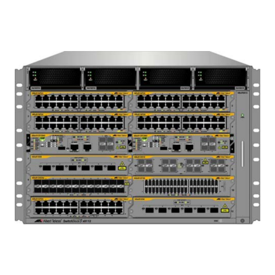
Chapter 1: Chassis and Power Supplies Grounding AC Power Power Supply Cord Sockets Interfaces (Opto-couplers) Figure 3. Rear View of the AT-SBx8112 Chassis Figure 4 is an example of a fully populated chassis. Figure 4. AT-SBx8112 Chassis with Line Cards, Controller Cards, and Power Supplies Section I: Hardware Overview... -
Page 25: Slots For The Ethernet Line And Controller Cards
SwitchBlade x8112 Chassis Switch and AT-SBx81CFC960 Card Installation Guide Slots for the Ethernet Line and Controller Cards The chassis has slots for ten Ethernet line cards and two AT- SBx81CFC960 Controller Cards. The slot definitions are predefined and may not be changed. Figure 5 identifies the slots. -
Page 26: Power Supplies And Power Supply Slots
Figure 6. Power Supply Units Note Allied Telesis is discontinuing the AT-SBxPWRSYS1 AC Power Supply and replacing it with the AT-SBxPWRSYS2 AC Power Supply. The power supplies are installed in the four slots across the top of the front of the chassis. -
Page 27: Figure 7: Power Supply Slots
SwitchBlade x8112 Chassis Switch and AT-SBx81CFC960 Card Installation Guide Slot A Slot B Slot C Slot D PoE Power PoE Power System Power System Power Supply Supply Supply Supply Figure 7. Power Supply Slots Slots C and D are for system power supplies. The three system power supplies are listed here: ... -
Page 28: Leds
The AT-SBxPWRSYS2 AC System Power Supply was added to the management software in release 5.4.5-1. It will work with earlier releases, but Allied Telesis recommends updating the software on controller cards with previous versions to the latest release to ensure full compatibility. -
Page 29: Table 1. Leds On The At-Sbxpwrsys1 And At-Sbxpwrsys2 Power Supplies
SwitchBlade x8112 Chassis Switch and AT-SBx81CFC960 Card Installation Guide Table 1. LEDs on the AT-SBxPWRSYS1 and AT-SBxPWRSYS2 Power Supplies State Description Solid Green The power supply is receiving AC power that is within the normal operating range. The power supply is not receiving power from the AC power source. -
Page 30: Table 3. Leds On The At-Sbxpwrpoe1 Poe Power Supply
Chapter 1: Chassis and Power Supplies Table 3. Table 3. LEDs on the AT-SBxPWRPOE1 PoE Power Supply State Description Solid Green The power supply is receiving AC power that is within the normal operating range. The power supply is not receiving power from the AC power source. -
Page 31: At-Sbxfan12 Module
SwitchBlade x8112 Chassis Switch and AT-SBx81CFC960 Card Installation Guide AT-SBxFAN12 Module The AT-SBxFAN12 Module, shown in Figure 8, is the cooling unit for the chassis. It is a field- replaceable assembly that is factory installed and shipped with the AT-SBx8112 Chassis. -
Page 32: Power Supply Interfaces (Opto-Couplers)
Chapter 1: Chassis and Power Supplies Power Supply Interfaces (Opto-couplers) The chassis has two power supply interfaces, also referred to as opto- couplers, in the lower right corner on the rear panel. The interfaces, labeled Power Supply Interface, are used by the active master controller card to obtain status information from the power supplies. -
Page 33: Table 5. Power Led On The Power Supply Interface
SwitchBlade x8112 Chassis Switch and AT-SBx81CFC960 Card Installation Guide Table 5. Power LED on the Power Supply Interface State Description Solid Green The interface is operating normally. Here are the possible conditions for this LED state: The corresponding power supply Power slots of the interface are empty. - Page 34 Chapter 1: Chassis and Power Supplies Section I: Hardware Overview...
-
Page 35: Chapter 2: Ethernet Line Cards
Chapter 2 Ethernet Line Cards This chapter describes the Ethernet line cards for the SwitchBlade x8112 Chassis Switch in the following sections: “Ethernet Line Cards” on page 36 “AT-SBx81GT24 Line Card” on page 37 “AT-SBx81GT40 Line Card” on page 39 ... -
Page 36: Ethernet Line Cards
Chapter 2: Ethernet Line Cards Ethernet Line Cards The Ethernet line cards are shown in Figure 10. AT-SBx81GT24 Ethernet Line Card with 24 10/100/1000Base-T twisted pair ports. AT-SBx81GT40 Ethernet Line Card with 40 10/100/1000Base-T twisted pair ports, with RJ point 5 connectors. -
Page 37: At-Sbx81Gt24 Line Card
SwitchBlade x8112 Chassis Switch and AT-SBx81CFC960 Card Installation Guide AT-SBx81GT24 Line Card The AT-SBx81GT24 Line Card, shown in Figure 11, is a Gigabit Ethernet switch. Figure 11. AT-SBx81GT24 Line Card Here are the main features of the line card: ... -
Page 38: Figure 12: Port Leds On The At-Sbx81Gt24 Line Card
Chapter 2: Ethernet Line Cards Figure 12. Port LEDs on the AT-SBx81GT24 Line Card Table 6. Port LEDs on the AT-SBx81GT24 Line Card State Description Solid Green The port has established an 1000 Mbps link to a network device. Flashing The port is transmitting or receiving data at Green 1000 Mbps. -
Page 39: At-Sbx81Gt40 Line Card
SwitchBlade x8112 Chassis Switch and AT-SBx81CFC960 Card Installation Guide AT-SBx81GT40 Line Card The AT-SBx81GT40 Line Card, shown in Figure 13, is a Gigabit Ethernet switch. Figure 13. AT-SBx81GT40 Line Card Here are the main features of the line card: ... -
Page 40: Leds
Chapter 2: Ethernet Line Cards LEDs The LEDs for a port on the AT-SBx81GT40 Line Card are found on the RJ point 5 cable connector. The LEDs are shown in Figure 14. LEDs Figure 14. Port LEDs on an RJ Point 5 Cable Connector for the AT- SBx81GT40 Line Card Only the left LED is active. -
Page 41: Table 7. Port Leds On The At-Sbx81Gt40 Line Card
SwitchBlade x8112 Chassis Switch and AT-SBx81CFC960 Card Installation Guide Table 7. Port LEDs on the AT-SBx81GT40 Line Card State Description Solid Green The port has established an 1000 Mbps link to a network device. Flashing The port is transmitting or receiving data at Green 1000 Mbps. -
Page 42: At-Sbx81Gp24 Poe Line Card
Chapter 2: Ethernet Line Cards AT-SBx81GP24 PoE Line Card The AT-SBx81GP24 PoE Line Card, shown in Figure 16, is a Gigabit Ethernet switch with Power over Ethernet Plus (PoE+) on all the ports. Figure 16. AT-SBx81GP24 PoE Line Card Here are the main features of the line card: ... -
Page 43: Leds
SwitchBlade x8112 Chassis Switch and AT-SBx81CFC960 Card Installation Guide LEDs Each port on the AT-SBx81GP24 PoE Line Card has two LEDs. The LEDs are shown in Figure 17 and described in Table 8. Figure 17. Port LEDs on the AT-SBx81GP24 PoE Line Card Table 8. - Page 44 Chapter 2: Ethernet Line Cards Table 8. Port LEDs on the AT-SBx81GP24 PoE Line Card (Continued) State Description This LED state can result from the following conditions: The port is not connected to a PD. The PD is powered off. ...
-
Page 45: At-Sbx81Gs24A Sfp Line Card
Non-blocking full wire speed switching on all packet sizes, with two AT-SBx81CFC960 Controller Fabric Cards. Hot swappable Contact your Allied Telesis sales representative for a list of supported transceivers. LEDs The SFP slots on the AT-SBx81GS24a SFP Line Card have one LED each, as shown in Figure 19 on page 46 and described in Table 9 on page 46. -
Page 46: Figure 19: Port Leds On The At-Sbx81Gs24A Sfp Line Card
Chapter 2: Ethernet Line Cards Figure 19. Port LEDs on the AT-SBx81GS24a SFP Line Card Table 9. Port LEDs on the AT-SBx81GS24a SFP Line Card LED State Description The SFP transceiver in the slot has established a Solid Amber 10 or 100 Mbps link to a network device. The SFP transceiver is transmitting and/or Blinking Amber receiving data at 10 or 100 Mbps. -
Page 47: At-Sbx81Xs6 Sfp+ Line Card
– 9710 bytes for ports operating at 10 or 100 Mbps. – 10240 bytes for ports operating at 1000 Mbps Hot swappable Contact your Allied Telesis sales representative for a list of supported transceivers. LEDs The AT-SBx81XS6 Line Card has one LED for each SFP+ slot. The LED is shown in Figure 21 and described in Table 10 on page 48. -
Page 48: Table 10. Sfp+ Slot Leds On The At-Sbx81Xs6 Line Card
Chapter 2: Ethernet Line Cards Table 10. SFP+ Slot LEDs on the AT-SBx81XS6 Line Card State Description Solid Green The transceiver has established a link with a network device. Flashing The transceiver is transmitting or receiving data at Green 10 Gbps. This LED state can result from the following conditions: ... -
Page 49: At-Sbx81Xs16 Sfp+ Line Card
Jumbo frame support of up to 10240 bytes Hot swappable Contact your Allied Telesis sales representative for a list of supported transceivers. Note The AT-SBx81XS16 Line Card is supported in slots 1 to 4, 8, and 10 in the AT-SBx8112 Chassis. The card is not supported in slots 7, 9, 11, and 12. -
Page 50: Figure 23: Sfp+ Slot Leds On The At-Sbx81Xs16 Line Card
Chapter 2: Ethernet Line Cards Top SFP+ Slot LED Bottom SFP+ Slot LED Figure 23. SFP+ Slot LEDs on the AT-SBx81XS16 Line Card Table 11. SFP+ Slot LEDs on the AT-SBx81XS16 Line Card State Description Solid Green The transceiver has established a 10 Gbps link with a network device. -
Page 51: 10/100/1000Base-T Twisted Pair Ports
SwitchBlade x8112 Chassis Switch and AT-SBx81CFC960 Card Installation Guide 10/100/1000Base-T Twisted Pair Ports This section applies to the 10/100/1000Base-T ports on the AT- SBx81GT24, AT-SBx81GT40, and AT-SBx81GP24 PoE Ethernet Line Cards. Connector Type The ports on the AT-SBx81GT24 and AT-SBx81GP24 Line Cards have 8- pin RJ-45 connectors. -
Page 52: Cable Requirements
Patch cables for the AT-SBx81GT40 Line Card, in lengths of 1 meter and 3 meters with RJ point 5 and RJ-45 connectors, are available from Allied Telesis. Contact your Allied Telesis sales representative for information. The cable requirements for the PoE ports on the AT-SBx81GP24 Ethernet Line Card are given in Table 13 on page 52. -
Page 53: Automatic Mdix Detection
SwitchBlade x8112 Chassis Switch and AT-SBx81CFC960 Card Installation Guide Table 13. Twisted Pair Cable for the AT-SBx81GP24 Line Card (Continued) 10Mbps 100Mbps 1000Mbps Cable Type Non- Non- Non- PoE+ PoE+ PoE+ Standard TIA/EIA 568- A-compliant Category 5 shielded or unshielded... -
Page 54: Power Over Ethernet On The At-Sbx81Gp24 Line Card
Chapter 2: Ethernet Line Cards Power over Ethernet on the AT-SBx81GP24 Line Card This section applies to the AT-SBx81GP24 PoE Line Card. The twisted- pair ports on the line card support Power over Ethernet (PoE). PoE is a mechanism by which the ports supply power to network devices over the twisted pair cables that carry the network traffic. -
Page 55: Power Budget
The numbers assume that the powered devices require the maximum amount of power for their classes. Note The maximum number of PoE ports in the SwitchBlade x8112 Switch is 240 ports. Table 15. Maximum Number of Powered Devices... - Page 56 Chapter 2: Ethernet Line Cards support PDs that receive power using Alternative A. PDs that comply with the IEEE 802.3af and 802.3at standards are required to support both power delivery methods. However, non-standard PDs and PDs that were manufactured before the completion of the IEEE 802.3af and 802.3at standards and that support only Alternative B will not work with the AT-SBx81GP24 PoE Line Card.
-
Page 57: Chapter 3: At-Sbx81Cfc960 Controller Fabric Card
Chapter 3 AT-SBx81CFC960 Controller Fabric Card This chapter describes the AT-SBx81CFC960 Controller Fabric Card in the following sections: “Controller Fabric Cards for the AT-SBx8112 Chassis” on page 58 “Hardware Components on the AT-SBx81CFC960 Card” on page 60 “Guidelines”... -
Page 58: Controller Fabric Cards For The At-Sbx8112 Chassis
Chapter 3: AT-SBx81CFC960 Controller Fabric Card Controller Fabric Cards for the AT-SBx8112 Chassis There are two controller fabric cards for the AT-SBx8112 Chassis. The cards are listed here: AT-SBx81CFC400 Card AT-SBx81CFC960 Card The controller fabric cards are shown in Figure 24. AT-SBx81CFC400 Controller Fabric Card AT-SBx81CFC960 Controller Fabric Card Figure 24. - Page 59 SwitchBlade x8112 Chassis Switch and AT-SBx81CFC960 Card Installation Guide information on the AT-SBx81CFC400 Card, refer to the SwitchBlade x8112 Chassis Switch and AT-SBx81CFC400 Card Installation Guide. Note You may not install both types of controller cards in the same chassis. When installing two controller cards in the chassis, be sure both cards are the same type.
-
Page 60: Hardware Components On The At-Sbx81Cfc960 Card
Chapter 3: AT-SBx81CFC960 Controller Fabric Card Hardware Components on the AT-SBx81CFC960 Card The components on the faceplate of the AT-SBx81CFC960 Controller Fabric Card are identified in Figure 25 and briefly described in Table 16. eco-friendly Button Status SBx Linecard Four Slots for 10Gbps SFP+ LEDs Status LEDs Transceivers... - Page 61 SwitchBlade x8112 Chassis Switch and AT-SBx81CFC960 Card Installation Guide Table 16. Components on the AT-SBx81CFC960 Controller Fabric Card Component Description Slots for Transceivers Supports four 10Gbps SFP+ transceivers. The transceivers may be used for these two functions: - Uplink ports for the Ethernet line cards.
-
Page 62: Guidelines
Chapter 3: AT-SBx81CFC960 Controller Fabric Card Guidelines Here are several functions of the controller card: — Chassis Management The controller card is used to monitor and configure the parameter settings on the Ethernet line cards. The controller card supports local management sessions through the Console RS-232 port and remote management sessions with Telnet, Secure Shell (SSH), or SNMP clients on workstations on your network. - Page 63 SwitchBlade x8112 Chassis Switch and AT-SBx81CFC960 Card Installation Guide controller card. The chassis may have either one or two controller cards. Two controller cards are recommended for redundancy and to increase the per slot backplane bandwidth from up to 80 to 160Gbps.
-
Page 64: Dual Controller Cards
Chapter 3: AT-SBx81CFC960 Controller Fabric Card Dual Controller Cards You may install either one or two controller cards in the chassis. Here are the advantages to having two controller cards in the chassis. Having a second controller card improves the performance of the chassis by increasing the backplane bandwidth for the Ethernet line cards. - Page 65 SwitchBlade x8112 Chassis Switch and AT-SBx81CFC960 Card Installation Guide One of the controller cards becomes the active master. In normal operations, this is the controller card in slot 5. The active master manages the system and processes CPU bound network traffic. The standby master...
-
Page 66: Sys Status Leds
Chapter 3: AT-SBx81CFC960 Controller Fabric Card SYS Status LEDs The SYS (System) Status LEDs on the controller fabric card display general status information about the controller card, power supplies, and fan module. The LEDs are defined in Table 17 on page 66. Table 17. - Page 67 SwitchBlade x8112 Chassis Switch and AT-SBx81CFC960 Card Installation Guide Table 17. SYS (System) Status LEDs (Continued) State Description Solid Green Indicates that the fan module is operating properly. Flashing Indicates that the fan module has a problem. The Amber fans are operating below the normal operating range or have stopped.
-
Page 68: Eco-Friendly Button
Chapter 3: AT-SBx81CFC960 Controller Fabric Card eco-friendly Button You may use the eco-friendly button on the controller card to turn the LEDs on or off. You may turn off the LEDs when you are not using them to monitor the control and Ethernet line cards, to conserve electricity. When the LEDs are off, the overall power consumption of the chassis is slightly reduced, approximately 3 watts in a system with 240 active copper ports. -
Page 69: Sbx Linecard Status Leds
SwitchBlade x8112 Chassis Switch and AT-SBx81CFC960 Card Installation Guide SBx Linecard Status LEDs The SBx Linecard Status LEDs display general status information about the Ethernet line cards and controller cards. There is one LED for each slot. If the chassis has two controller cards, the SBx Status LEDs on both cards are active. -
Page 70: Sfp+ Slots
Chapter 3: AT-SBx81CFC960 Controller Fabric Card SFP+ Slots The controller card has four SFP+ slots on the front panel. They are numbered 1 to 4 and may be used with Allied Telesis AT-SP10TW direct connect cables or SFP+ 10G transceivers for the following functions. ... -
Page 71: Table 19. Leds For The Sfp+ Slots On The At-Sbx81Cfc960 Controller Card
SwitchBlade x8112 Chassis Switch and AT-SBx81CFC960 Card Installation Guide Table 19. Table 19. LEDs for the SFP+ Slots on the AT-SBx81CFC960 Controller Card State Description Solid Green The transceiver has established a link with a network device. Flashing The transceiver is transmitting or receiving data at Green 10Gbps. -
Page 72: Console (Rs-232) Port
Chapter 3: AT-SBx81CFC960 Controller Fabric Card Console (RS-232) Port The Console Port is used to conduct local management sessions with the switch. Local management sessions are established with a terminal or PC with a terminal emulation program, and the management cable that comes with the card. -
Page 73: Ethernet Management Port (Net Mgmt)
SwitchBlade x8112 Chassis Switch and AT-SBx81CFC960 Card Installation Guide Ethernet Management Port (NET MGMT) The controller card uses the NET MGMT port as a separate routed eth0 interface. The interface is not part of the switching matrix of the Ethernet line cards, but the CPU on the controller card can route traffic in or out of the port from the line cards. -
Page 74: Table 20. Net Mgmt Port Led
Chapter 3: AT-SBx81CFC960 Controller Fabric Card Table 20. NET MGMT Port LED State Description Solid Green The port has a valid 1000 Mbps link. Flashing The port is transmitting or receiving data at Green 1000 Mbps. Solid Amber The port has a valid 10 or 100 Mbps link. Flashing The port is transmitting or receiving data at Amber... -
Page 75: Usb Port
SwitchBlade x8112 Chassis Switch and AT-SBx81CFC960 Card Installation Guide USB Port The USB port supports a flash drive. You may use a flash drive to perform the following management functions: Use Allied Telesis Management Framework to provide a centralized network backup location. -
Page 76: Reset Button
Chapter 3: AT-SBx81CFC960 Controller Fabric Card Reset Button You may use the Reset button to reset either the controller card or all of the cards in the chassis. The action depends on the number of AT- SBx81CFC960 Controller Cards in the chassis and, if the chassis has two controller cards, whether you reset the active or standby master controller card. - Page 77 SwitchBlade x8112 Chassis Switch and AT-SBx81CFC960 Card Installation Guide Note To reset individual line cards in the chassis, use the REBOOT or RELOAD command in the AlliedWare Plus Operating System. Section I: Hardware Overview...
-
Page 78: Alliedware Plus Software Releases For The Hardware Components
Chapter 3: AT-SBx81CFC960 Controller Fabric Card AlliedWare Plus Software Releases for the Hardware Components Table 21 lists the releases of the AlliedWare Plus Operating System for the hardware components of the SwitchBlade x8112 product. Table 21. AlliedWare Plus Operating System Releases for the Hardware Components... -
Page 79: Section Ii: Installing The Chassis
Section II Installing the Chassis This section contains the following chapters: Chapter 4, “Safety Precautions and Site Requirements” on page 81 Chapter 5, “Installing the Chassis in an Equipment Rack” on page 89 Chapter 6, “Installing the Power Supplies” on page 105 ... -
Page 81: Chapter 4: Safety Precautions And Site Requirements
This chapter contains the safety precautions and guidelines for selecting a site for the chassis. The chapter contains the following sections: “Reviewing Safety Precautions” on page 82 “Selecting a Site for the SwitchBlade x8112” on page 86 “Installation Tools and Material” on page 88... -
Page 82: Reviewing Safety Precautions
Chapter 4: Safety Precautions and Site Requirements Reviewing Safety Precautions Please review the following safety precautions before you begin to install the switch. Note The indicates that a translation of the safety statement is available for viewing in portable document format (PDF) titled Translated Safety Statements from our web site at www.alliedtelesis.com/support. - Page 83 SwitchBlade x8112 Chassis Switch and AT-SBx81CFC960 Card Installation Guide Note Pluggable Equipment. The socket outlet shall be installed near the equipment and shall be easily accessible. E5 Caution Air vents must not be blocked and must have free access to the room ambient air for cooling.
- Page 84 Remove all metal jewelry, such as rings and watches, before installing or removing a line card from a powered-on chassis. Warning The chassis may be heavy and awkward to lift. Allied Telesis recommends that you get assistance when mounting the chassis in an equipment rack. E28 Warning This unit might have more than one power cord.
- Page 85 SwitchBlade x8112 Chassis Switch and AT-SBx81CFC960 Card Installation Guide Warning To reduce the risk of electric shock, the PoE ports on this product must not connect to cabling that is routed outside the building where this device is located. E40 Warning This product may have multiple AC power cords installed.
-
Page 86: Selecting A Site For The Switchblade X8112
Chapter 4: Safety Precautions and Site Requirements Selecting a Site for the SwitchBlade x8112 Please perform the following procedure to determine the suitability of the site for the chassis: 1. Verify that the equipment rack is safely secured so that it will not tip over. -
Page 87: Figure 26: 100 - 125 Vac 125 V Nema 5-20 Plug And Receptacle
SwitchBlade x8112 Chassis Switch and AT-SBx81CFC960 Card Installation Guide Figure 26. 100 - 125 VAC 125 V NEMA 5-20 Plug and Receptacle Section II: Installing the Chassis... -
Page 88: Installation Tools And Material
Chapter 4: Safety Precautions and Site Requirements Installation Tools and Material Here are the installation tools and material you need to have to install the product. Installing the chassis in an equipment rack requires the following items: #2 Phillips-head screwdriver ... -
Page 89: Chapter 5: Installing The Chassis In An Equipment Rack
Chapter 5 Installing the Chassis in an Equipment Rack This chapter describes how to install the AT-SBx8112 Chassis in an equipment rack. This chapter contains the following sections: “Required Tools and Material” on page 90 “Preparing the Equipment Rack” on page 91 ... -
Page 90: Required Tools And Material
#2 Phillips-head 20 inch-lbs torque screwdriver (optional) Warning The chassis may be heavy and awkward to lift. Allied Telesis recommends that you get assistance when mounting the chassis in an equipment rack. E30 Section II: Installing the Chassis... -
Page 91: Preparing The Equipment Rack
SwitchBlade x8112 Chassis Switch and AT-SBx81CFC960 Card Installation Guide Preparing the Equipment Rack This section explains how to prepare the equipment rack for the chassis. The procedure requires the following items: #2 Phillips-head screwdriver (not provided) Two equipment rack screws (not provided) -
Page 92: Figure 27: Reserving Vertical Rack Space
Chapter 5: Installing the Chassis in an Equipment Rack Figure 27. Reserving Vertical Rack Space Section II: Installing the Chassis... -
Page 93: Figure 28: Rack Mounting Hole Locations
SwitchBlade x8112 Chassis Switch and AT-SBx81CFC960 Card Installation Guide 3. Identify the lowest 1/2” screw hole pattern on the rack mounting rails within the space reserved for the AT-SBx8112 Chassis. 4. Install one rack mount screw in each vertical rail, at the same height in the top screw hole of the lowest 1/2”... -
Page 94: Unpacking The At-Sbx8112 Chassis
2. Verify the contents of the shipping container by referring to Figure 29 here and Figure 30 on page 95. If any item is missing or damaged, contact your Allied Telesis sales representative for assistance. One AT-SBx8112 Chassis One AT-SBxFAN12 Module pre-... -
Page 95: Figure 30: Components Of The At-Sbx8112 Chassis (Continued)
SwitchBlade x8112 Chassis Switch and AT-SBx81CFC960 Card Installation Guide Two equipment rack brackets pre-installed on the sides of the chassis. One shipping brace pre-installed diagonally across the line card slots on the front panel One wrist strap Figure 30. Components of the AT-SBx8112 Chassis (Continued) -
Page 96: Adjusting The Equipment Rack Brackets
Chapter 5: Installing the Chassis in an Equipment Rack Adjusting the Equipment Rack Brackets The chassis has two pre-installed equipment rack brackets. You may adjust the brackets so that the front of the chassis is flush with, extends beyond, or is recessed behind the front of the equipment rack. You may also install the brackets so that the rear panel of the chassis is flush with the front of the equipment rack. -
Page 97: Figure 31: Rack Mounting Bracket Locations
SwitchBlade x8112 Chassis Switch and AT-SBx81CFC960 Card Installation Guide Factory Installed - Flush with Rack Rails “Dim X” “Dim X” “Dim X” “Dim X” Figure 31. Rack Mounting Bracket Locations Figure 32. Rack Bracket Locations for Reverse Position of Chassis... -
Page 98: Installing The At-Sbx8112 Chassis In The Equipment Rack
Warning The chassis may be heavy and awkward to lift. Allied Telesis recommends that you get assistance when mounting the chassis in an equipment rack. E30... -
Page 99: Figure 33: Lifting The At-Sbx8112 Chassis Into The Equipment Rack
SwitchBlade x8112 Chassis Switch and AT-SBx81CFC960 Card Installation Guide 2. Lift the AT-SBx8112 Chassis into the equipment rack and set the bottom of the equipment rack brackets firmly on the two equipment rack screws you installed in “Preparing the Equipment Rack” on page 91, as shown in Figure 33. -
Page 100: Figure 34: Installing The Rack Mount Screws
Figure 34. Installing the Rack Mount Screws 5. Tighten all eight screws to secure the chassis to the equipment rack, Allied Telesis recommends tightening the screws to 10 inch-lbs. 6. Go to “Removing the Shipping Brace” on page 101. Section II: Installing the Chassis... -
Page 101: Removing The Shipping Brace
SwitchBlade x8112 Chassis Switch and AT-SBx81CFC960 Card Installation Guide Removing the Shipping Brace Now that the chassis is installed in the equipment rack, you may remove the shipping brace from the front of the unit. To remove the shipping brace, remove the six mounting screws with a #2 Phillips-head screwdriver (not provided). -
Page 102: Installing The Chassis Grounding Wire
Chapter 5: Installing the Chassis in an Equipment Rack Installing the Chassis Grounding Wire This procedure explains how to connect a grounding wire to the chassis. The chassis requires a permanent connection for the line cards and power supplies to a good earth ground. The procedure requires the following items: ... -
Page 103: Figure 38: Attaching The Grounding Wire To The Grounding Lug
SwitchBlade x8112 Chassis Switch and AT-SBx81CFC960 Card Installation Guide 3. Insert one end of the grounding wire into the grounding lug, as shown in Figure 38, and use a crimping tool to secure the wire to the grounding lug. Figure 38. Attaching the Grounding Wire to the Grounding Lug 4. - Page 104 Chapter 5: Installing the Chassis in an Equipment Rack Section II: Installing the Chassis...
-
Page 105: Chapter 6: Installing The Power Supplies
Chapter 6 Installing the Power Supplies This chapter explains how to install the power supplies. It has the following sections: “Protecting Against Electrostatic Discharge (ESD)” on page 106 “Installing AT-SBxPWRSYS1 or AT-SBxPWRSYS2 AC System Power Supplies” on page 107 ... -
Page 106: Protecting Against Electrostatic Discharge (Esd)
Caution Electrostatic Discharge (ESD) can damage the components on the SwitchBlade x8112 line cards and power supplies. Be sure to follow proper ESD procedures during the installation. To guard against ESD, perform this procedure: 1. -
Page 107: Installing At-Sbxpwrsys1 Or At-Sbxpwrsys2 Ac System Power Supplies
System power supplies are installed in slots C and D in the chassis. Refer to Figure 41 on page 108. If you are installing only one power supply, you may install it in either slot, but Allied Telesis recommends slot D because the slot does not come with a blank power supply panel. -
Page 108: Figure 41: Power Supply Slots
Chapter 6: Installing the Power Supplies AT-SBxPWRSYS1 AT-SBxPWRPOE1 or AT-SBxPWRSYS2 Power Supply Slots Power Supply Slots Figure 41. Power Supply Slots Caution The AT-SBxPWRSYS1 and AT-SBxPWRSYS2 AC System Power Supplies will not work in slot A or B. 2. If the chassis already has a power supply in slot D, remove the blank power supply panel from slot C by lifting the blank panel handle and sliding it out of the slot, as shown in Figure 42. -
Page 109: Figure 43: Items Included With The At-Sbxpwrsys1 Or At-Sbxpwrsys2 Ac System Power Supply
SwitchBlade x8112 Chassis Switch and AT-SBx81CFC960 Card Installation Guide 3. Remove the new power supply from the shipping package and verify the package contents, listed in Figure 43. If any item is missing or damaged, contact your Allied Telesis sales representative for assistance. One AT-SBxPWRSYS1 or... -
Page 110: Figure 44: Unlocking The Handle On The Power Supply
Chapter 6: Installing the Power Supplies 4. Move the locking handle on the power supply to the unlocked or up position. See Figure 44. Figure 44. Unlocking the Handle on the Power Supply 5. Align and insert the power supply into the power supply slot. Figure 45 shows the power supply installed in slot D. -
Page 111: Figure 46: Lowering The Handle On The At-Sbxpwrsys1 Or At-Sbxpwrsys2 Ac System Power Supply
SwitchBlade x8112 Chassis Switch and AT-SBx81CFC960 Card Installation Guide 6. Lower the power supply locking handle to secure the power supply to the chassis, as shown in Figure 46. Figure 46. Lowering the Handle on the AT-SBxPWRSYS1 or AT- SBxPWRSYS2 AC System Power Supply... - Page 112 Chapter 6: Installing the Power Supplies Note Retain the tie wrap that comes with the power supply. You will use it to secure the power cord to the chassis when you power on the unit in “Powering On AT-SBxPWRSYS1 or AT-SBxPWRSYS2 AC System Power Supplies”...
-
Page 113: Installing At-Sbxpwrpoe1 Poe Power Supplies
SwitchBlade x8112 Chassis Switch and AT-SBx81CFC960 Card Installation Guide Installing AT-SBxPWRPOE1 PoE Power Supplies This section contains the installation procedure for the AT-SBxPWRPOE1 Power Supply, for the PoE+ ports on the AT-SBx81GP24 PoE Line Card. For background information, refer to “Power Supplies and Power Supply Slots”... -
Page 114: Figure 47: Removing The Blank Slot Cover From Power Supply Slot A
3. Remove the power supply from the shipping package and verify that the shipping package contains the items listed in Figure 48 on page 115. If any item is missing or damaged, contact your Allied Telesis sales representative for assistance. Section II: Installing the Chassis... -
Page 115: Figure 48: Items Included With The At-Sbxpwrpoe1 Power Supply Module
SwitchBlade x8112 Chassis Switch and AT-SBx81CFC960 Card Installation Guide One AT-SBxPWRPOE1 Power Supply Module One regional AC power cord One tie wrap Figure 48. Items Included with the AT-SBxPWRPOE1 Power Supply Module Note Store the packaging material in a safe location. You must use the original shipping material if you need to return the unit to Allied Telesis. -
Page 116: Figure 49: Unlocking The Handle On The At-Sbxpwrpoe1 Power Supply
Chapter 6: Installing the Power Supplies Figure 49. Unlocking the Handle on the AT-SBxPWRPOE1 Power Supply 5. Align and insert the AT-SBxPWRPOE1 Module into slot A or B. Figure 50 shows the power supply module aligned in slot A. Caution The AT-SBxPWRPOE1 AC Power Supply will not work in slot C or Figure 50. -
Page 117: Figure 51: Locking The Handle On The At-Sbxpwrpoe1 Power Supply
SwitchBlade x8112 Chassis Switch and AT-SBx81CFC960 Card Installation Guide 6. Lower the locking handle of the power supply module to secure the module in the slot, as shown in Figure 51. Figure 51. Locking the Handle on the AT-SBxPWRPOE1 Power Supply... -
Page 118: Installing At-Sbxpwrsys1 Dc System Power Supplies
System power supplies are installed in slots C and D in the chassis. Refer to Figure 41 on page 108. If you are installing only one power supply, you may install it in either slot, but Allied Telesis recommends slot D because the slot does not come with a blank power supply panel. -
Page 119: Figure 52: Removing The Blank Slot Cover From Power Supply Slot C
3. Remove the power supply from the shipping package and verify that the shipping package contains the items listed in Figure 53 on page 120. If any item is missing or damaged, contact your Allied Telesis sales representative for assistance. Section II: Installing the Chassis... -
Page 120: Figure 53: Items Included With The At-Sbxpwrsys1 Dc Power Supply Module
Chapter 6: Installing the Power Supplies One AT-SBxPWRSYS1 DC System Power Supply Two straight power wire ring lugs One grounding wire ring lug Two right angle power wire ring lugs Figure 53. Items Included with the AT-SBxPWRSYS1 DC Power Supply Module Note Store the packaging material in a safe location. -
Page 121: Figure 54: On/Off Switch On The At-Sbxpwrsys1 Dc Power Supply
SwitchBlade x8112 Chassis Switch and AT-SBx81CFC960 Card Installation Guide On/Off Switch Figure 54. On/Off Switch on the AT-SBxPWRSYS1 DC Power Supply 5. With a #2 Phillips-head screwdriver, loosen the handle locking screw on the power supply, as shown in Figure 55. -
Page 122: Figure 56: Raising Handle On The At-Sbxpwrsys1 Dc Power Supply
Chapter 6: Installing the Power Supplies Figure 56. Raising Handle on the AT-SBxPWRSYS1 DC Power Supply 7. Align and insert the AT-SBxPWRSYS1 Module into slot C or D. Figure 57 shows the power supply installed in slot D. Caution The AT-SBxPWRSYS1 DC System Power Supply will not work in slot A or B. -
Page 123: Figure 58: Locking The Handle On The At-Sbxpwrsys1 Dc System Power Supply
SwitchBlade x8112 Chassis Switch and AT-SBx81CFC960 Card Installation Guide 8. Lower the locking handle of the power supply module to secure the module in the slot, as shown in Figure 58. Figure 58. Locking the Handle on the AT-SBxPWRSYS1 DC System... - Page 124 Chapter 6: Installing the Power Supplies Section II: Installing the Chassis...
-
Page 125: Chapter 7: Installing The At-Sbx81Cfc960 Control Card And Ethernet Line Cards
Chapter 7 Installing the AT-SBx81CFC960 Control Card and Ethernet Line Cards This chapter describes how to install the control and Ethernet line cards. The chapter has the following sections: “Guidelines to Handling the Controller and Line Cards” on page 126 ... -
Page 126: Guidelines To Handling The Controller And Line Cards
Chapter 7: Installing the AT-SBx81CFC960 Control Card and Ethernet Line Cards Guidelines to Handling the Controller and Line Cards Please observe the following guidelines when handling the controller and Ethernet line cards: The cards are hot swappable and can be installed or removed while the chassis is powered on. -
Page 127: Figure 59: Aligning A Card In A Slot
SwitchBlade x8112 Chassis Switch and AT-SBx81CFC960 Card Installation Guide CORRECT INCORRECT INCORRECT Figure 59. Aligning a Card in a Slot Section II: Installing the Chassis... -
Page 128: Installing The At-Sbx81Cfc960 Controller Fabric Card
2. Remove the new AT-SBx81CFC960 Controller Fabric Card from the shipping package and verify the package contents, listed in Figure 61 on page 129. If any item is missing or damaged, contact your Allied Telesis sales representative for assistance. Section II: Installing the Chassis... -
Page 129: Figure 61: Items Included With The At-Sbx81Cfc960 Controller Card
SwitchBlade x8112 Chassis Switch and AT-SBx81CFC960 Card Installation Guide One AT-SBx81CFC960 Control Card One 2 m (6.6 ft) local management cable with RJ-45 (8P8C) and DB-9 (D-sub 9-pin) connectors. Figure 61. Items Included with the AT-SBx81CFC960 Controller Card Note Store the packaging material in a safe location. You should use the original shipping material if you need to return the unit to Allied Telesis. -
Page 130: Figure 63: Removing The Battery Insulator
Chapter 7: Installing the AT-SBx81CFC960 Control Card and Ethernet Line Cards Figure 63. Removing the Battery Insulator 5. Move the locking handles on the front panel to the open position, as shown in Figure 64. Figure 64. Opening the Locking Handles on the AT-SBx81CFC960 Controller Fabric Card 6. -
Page 131: Figure 65: Aligning The At-Sbx81Cfc960 Card In The Chassis Slot
SwitchBlade x8112 Chassis Switch and AT-SBx81CFC960 Card Installation Guide Figure 65. Aligning the AT-SBx81CFC960 Card in the Chassis Slot 7. Carefully slide the card into the slot. Caution Keep the card level with the chassis as you slide it into the slot. You might damage the components on the top or bottom of the card if you slide it in at an angle. -
Page 132: Figure 66: Closing The Locking Levers On The At-Sbx81Cfc960 Controller Fabric Card
Chapter 7: Installing the AT-SBx81CFC960 Control Card and Ethernet Line Cards Figure 66. Closing the Locking Levers on the AT-SBx81CFC960 Controller Fabric Card 9. Finger tighten the two thumbscrews on the card to secure the card to the chassis, as shown in Figure 67 on page 133. Section II: Installing the Chassis... -
Page 133: Figure 67: Tightening The Thumb Screws On The At-Sbx81Cfc960 Card
SwitchBlade x8112 Chassis Switch and AT-SBx81CFC960 Card Installation Guide Figure 67. Tightening the Thumb Screws on the AT-SBx81CFC960 Card 10. Tighten the screws with a # 2 Phillips-head screwdriver to secure the controller card to the chassis. Allied Telesis recommends tightening the screws to 5 inch-lbs. -
Page 134: Installing The Ethernet Line Cards
AT-SBx8112 Chassis. The card is not supported in slot 7, 9, 11, or 12. 2. Remove the line card from the shipping package. If it is missing or damaged, contact your Allied Telesis sales representative for assistance. Section II: Installing the Chassis... -
Page 135: Figure 69: Removing An Ethernet Line Card From The Anti-Static Bag
SwitchBlade x8112 Chassis Switch and AT-SBx81CFC960 Card Installation Guide Note Store the packaging material in a safe location. You should use the original shipping material if you need to return the unit to Allied Telesis. 3. Carefully remove the Ethernet line card from the anti-static bag. Refer to Figure 69. -
Page 136: Figure 70: Aligning An Ethernet Line Card In A Chassis Slot
Chapter 7: Installing the AT-SBx81CFC960 Control Card and Ethernet Line Cards Figure 70. Aligning an Ethernet Line Card in a Chassis Slot 5. Carefully slide the card into the slot. Caution Keep the card level with the chassis as you slide it into the slot. You might damage the components on the top or bottom of the card if you slide it in at an angle. -
Page 137: Figure 71: Seating An Ethernet Line Card On The Backplane Connector
SwitchBlade x8112 Chassis Switch and AT-SBx81CFC960 Card Installation Guide Figure 71. Seating an Ethernet Line Card on the Backplane Connector 7. Finger tighten the two thumbscrews on the sides of the line card to secure it to the chassis, as shown in Figure 72. - Page 138 8. Tighten the two screws with a # 2 Phillips-head screwdriver to secure the line card to the chassis. Allied Telesis recommends tightening the screws to 5 inch-lbs. 9. Repeat this procedure to install the remaining Ethernet line cards. 10. After installing the line cards. go to “Installing the Blank Slot Covers”...
-
Page 139: Installing The Blank Slot Covers
SwitchBlade x8112 Chassis Switch and AT-SBx81CFC960 Card Installation Guide Installing the Blank Slot Covers After installing the AT-SBx81CFC960 Controller Fabric Cards and Ethernet line cards, check the front panel for unused slots and cover them with the blank slot covers included with the chassis, as explained in this procedure. - Page 140 Chapter 7: Installing the AT-SBx81CFC960 Control Card and Ethernet Line Cards Allied Telesis recommends tightening the screws to 5 inch-lbs. 4. Repeat this procedure to cover the remaining empty slots with blank slot covers. 5. Store any unused blank panels in a secure location for future use.
-
Page 141: Chapter 8: Installing The Transceivers And Cabling The Ports
Chapter 8 Installing the Transceivers and Cabling the Ports This chapter describes how to install the fiber optic transceivers and attach the cables to the ports on the line cards. The chapter has the following sections: “Cabling Guidelines for the Twisted Pair Ports on the AT-SBx81GT24, AT-SBx81GT40, and AT-SBx81GP24 Line Cards”... -
Page 142: Cabling Guidelines For The Twisted Pair Ports On The At-Sbx81Gt24, At-Sbx81Gt40, And At-Sbx81Gp24 Line Cards
Chapter 8: Installing the Transceivers and Cabling the Ports Cabling Guidelines for the Twisted Pair Ports on the AT-SBx81GT24, AT-SBx81GT40, and AT-SBx81GP24 Line Cards Here are the guidelines to cabling the 10/100/1000Base-T twisted pair ports on the AT-SBx81GT24, AT-SBx81GP24, and AT-SBx81GT40 Line Cards: ... -
Page 143: Connecting Cables To The At-Sbx81Gt40 Line Card
SwitchBlade x8112 Chassis Switch and AT-SBx81CFC960 Card Installation Guide The default wiring configuration of the ports is automatic MDIX detection, which configures the MDI/MDIX setting automatically. This setting is appropriate for switch ports that are connected to network devices that also support the feature. -
Page 144: Figure 76: Connecting Cables To Ports On The At-Sbx81Gt40 Line Card
Chapter 8: Installing the Transceivers and Cabling the Ports Connecting a cable to a port in the top row. Release Tab Connecting a cable to a port in the bottom row. Figure 76. Connecting Cables to Ports on the AT-SBx81GT40 Line Card Section II: Installing the Chassis... -
Page 145: Guidelines To Installing Sfp And Sfp+ Transceivers
When you do remove this cover, retain it for future use. Your Allied Telesis sales representative can provide you with a list of supported transceivers for the line cards. The operational specifications and fiber optic cable requirements of the transceivers are provided in the documents included with the devices. -
Page 146: Installing Sfp Transceivers In The At-Sbx81Gs24A Line Card
Chapter 8: Installing the Transceivers and Cabling the Ports Installing SFP Transceivers in the AT-SBx81GS24a Line Card Please review the information in “Guidelines to Installing SFP and SFP+ Transceivers” on page 145 before performing this procedure. To install SFP transceivers in AT-SBx81GS24a Line Cards, perform the following procedure: 1. -
Page 147: Figure 79: Inserting The Sfp Transceiver In The At-Sbx81Gs24A Line Card
SwitchBlade x8112 Chassis Switch and AT-SBx81CFC960 Card Installation Guide 4. Slide the transceiver into the slot until it clicks into place, as shown in Figure 79. Figure 79. Inserting the SFP Transceiver in the AT-SBx81GS24a Line Card Note If you are ready to attach the fiber optic cable to the transceiver, continue with the next step. -
Page 148: Figure 80: Removing The Dust Cover From The Sfp Transceiver In The At-Sbx81Gs24A Line Card
Chapter 8: Installing the Transceivers and Cabling the Ports Figure 80. Removing the Dust Cover from the SFP Transceiver in the AT- SBx81GS24a Line Card Note The dust cover protects the fiber optic port on the SFP transceiver from dust contamination. It should not be removed until you are ready to connect the fiber optic cable. -
Page 149: Figure 82: Attaching A Fiber Optic Cable To An Sfp Transceiver In The At-Sbx81Gs24A Line Card
SwitchBlade x8112 Chassis Switch and AT-SBx81CFC960 Card Installation Guide 7. Connect the fiber optic cable to the port on the transceiver, as shown in Figure 82. The connector should snap into the port. Figure 82. Attaching a Fiber Optic Cable to an SFP Transceiver in the AT- SBx81GS24a Line Card 8. -
Page 150: Installing Sfp+ Transceivers In The At-Sbx81Xs6 Line Card
Chapter 8: Installing the Transceivers and Cabling the Ports Installing SFP+ Transceivers in the AT-SBx81XS6 Line Card Please review the information in “Guidelines to Installing SFP and SFP+ Transceivers” on page 145 before performing this procedure. To install 10 Gbps SFP+ transceivers in the AT-SBx81XS6 Line Card, perform the following procedure: 1. -
Page 151: Figure 84: Handle On Sfp+ Transceiver
SwitchBlade x8112 Chassis Switch and AT-SBx81CFC960 Card Installation Guide Handle Figure 84. Handle on SFP+ Transceiver 3. Slide the transceiver into the slot until it clicks into place, as shown in Figure 85. Figure 85. Installing an SFP+ Transceiver in the AT-SBx81XS6 Line Card... -
Page 152: Figure 86: Removing The Dust Cover From An Sfp+ Transceiver In The At-Sbx81Xs6 Line Card
Chapter 8: Installing the Transceivers and Cabling the Ports Figure 86. Removing the Dust Cover from an SFP+ Transceiver in the AT- SBx81XS6 Line Card Note The dust cover protects the fiber optic port on the SFP transceiver from dust contamination. It should not be removed until you are ready to connect the fiber optic cable. -
Page 153: Figure 88: Attaching A Fiber Optic Cable To An Sfp+ Transceiver In The At-Sbx81Xs6 Line Card
SwitchBlade x8112 Chassis Switch and AT-SBx81CFC960 Card Installation Guide 6. Connect the fiber optic cable to the port on the transceiver, as shown in Figure 88. The connector should snap into the port. Figure 88. Attaching a Fiber Optic Cable to an SFP+ Transceiver in the AT-SBx81XS6 Line Card 7. -
Page 154: Installing At-Sp10Tw Cables In The At-Sbx81Xs6 Line Card
Chapter 8: Installing the Transceivers and Cabling the Ports Installing AT-SP10TW Cables in the AT-SBx81XS6 Line Card This procedure explains how to connect AT-SP10TW Cables to the SFP+ slots in the AT-SBx81XS6 Line Card. The cables may be used in place of fiber optic cables and transceivers for 10 Gbps links of up to 7 meters. -
Page 155: Figure 90: Installing The At-Sp10Tw Cable In The At-Sbx81Xs6 Line Card
SwitchBlade x8112 Chassis Switch and AT-SBx81CFC960 Card Installation Guide The connector on the AT-SP10TW Cable has to be oriented such that the release tab is on top when you slide the connector into the slot. Release Figure 90. Installing the AT-SP10TW Cable in the AT-SBx81XS6 Line Card 3. -
Page 156: Installing Sfp+ Transceivers In The At-Sbx81Xs16 Line Card
Chapter 8: Installing the Transceivers and Cabling the Ports Installing SFP+ Transceivers in the AT-SBx81XS16 Line Card Please review the information in “Guidelines to Installing SFP and SFP+ Transceivers” on page 145 before performing this procedure. To install 10Gbps SFP+ transceivers in the AT-SBx81XS16 Line Card, perform the following procedure: 1. -
Page 157: Figure 92: Installing A Transceiver In The At-Sbx81Xs16 Line Card
SwitchBlade x8112 Chassis Switch and AT-SBx81CFC960 Card Installation Guide Handle Figure 92. Installing a Transceiver in the AT-SBx81XS16 Line Card Note If you are ready to attach the fiber optic cable to the transceiver, continue with the next step. Otherwise, repeat steps 1 to 2 to install the remaining SFP transceivers in the line cards. -
Page 158: Figure 94: Verifying The Position Of The Handle On The Transceiver In The At-Sbx81Xs16 Line Card
Chapter 8: Installing the Transceivers and Cabling the Ports Note The dust cover protects the fiber optic port on the transceiver from dust contamination. It should not be removed until you are ready to connect the fiber optic cable. 4. Before connecting the cable, verify the position of the handle on the transceiver. -
Page 159: Figure 95: Attaching A Fiber Optic Cable To A Transceiver In The At-Sbx81Xs16 Line Card
SwitchBlade x8112 Chassis Switch and AT-SBx81CFC960 Card Installation Guide Figure 95. Attaching a Fiber Optic Cable to a Transceiver in the AT- SBx81XS16 Line Card 6. Repeat this procedure to install additional transceivers in the AT- SBx81XS16 Line Cards. After installing and cabling the transceivers, do one of the following: ... -
Page 160: Installing At-Sp10Tw Cables In The At-Sbx81Xs16 Line Card
Chapter 8: Installing the Transceivers and Cabling the Ports Installing AT-SP10TW Cables in the AT-SBx81XS16 Line Card This procedure explains how to connect AT-SP10TW Cables to AT- SBx81XS16 Line Cards. The cables may be used in place of fiber optic cables and transceivers for 10 Gbps links of up to 7 meters. -
Page 161: Figure 97: Installing The At-Sp10Tw Cable In The At-Sbx81Xs16 Line Card
SwitchBlade x8112 Chassis Switch and AT-SBx81CFC960 Card Installation Guide even numbered slot, position the connector so that the release tab is on the bottom. Refer to Figure 97. Release Tab Release Tab Figure 97. Installing the AT-SP10TW Cable in the AT-SBx81XS16 Line Card 3. -
Page 162: Cabling The Net Mgmt Port On The At-Sbx81Cfc960 Card
Chapter 8: Installing the Transceivers and Cabling the Ports Cabling the NET MGMT Port on the AT-SBx81CFC960 Card For background information on the NET MGMT port on the controller card, refer to “Ethernet Management Port (NET MGMT)” on page 73. Note The NET MGMT port is referred to as “eth0”... - Page 163 SwitchBlade x8112 Chassis Switch and AT-SBx81CFC960 Card Installation Guide After cabling the NET MGMT port, do one of the following: To install and cable additional transceivers, go to the appropriate section in this chapter for instructions. After cabling all the ports in the chassis, go to Chapter 9, “Powering On the Chassis”...
-
Page 164: Installing Sfp+ Transceivers In The At-Sbx81Cfc960 Card
For background information on the SFP+ slots on the controller card, refer to “SFP+ Slots” on page 70. A list of supported SFP+ transceivers can be found on the Allied Telesis web site. Note The transceiver slots on the controller card do not support 1000Mbps SFP transceivers. -
Page 165: Figure 98: Removing A Dust Cover From An Sfp+ Slot In The At-Sbx81Cfc960 Controller Fabric Card
SwitchBlade x8112 Chassis Switch and AT-SBx81CFC960 Card Installation Guide Figure 98. Removing a Dust Cover from an SFP+ Slot in the AT- SBx81CFC960 Controller Fabric Card Note To protect the controller card from dust contamination, do not remove the dust plug from a transceiver slot until you are ready to install the transceiver. -
Page 166: Figure 100: Installing An Sfp+ Transceiver In The At-Sbx81Cfc960 Controller Fabric Card
Chapter 8: Installing the Transceivers and Cabling the Ports Figure 100. Installing an SFP+ Transceiver in the AT-SBx81CFC960 Controller Fabric Card Note If you are ready to attach the fiber optic cable to the transceiver, continue with the next step. Otherwise, repeat steps 1 to 3 to install additional SFP+ transceivers in the card. -
Page 167: Figure 102: Positioning The Handle On The Transceiver
SwitchBlade x8112 Chassis Switch and AT-SBx81CFC960 Card Installation Guide Note The dust cover protects the fiber optic port on the SFP+ transceiver from dust contamination. Do not remove it until you are ready to connect the fiber optic cable. 5. Verify the position of the handle on the transceiver. If the transceiver is in slot 1 or 3, the handle should be in the upright position, as shown in Figure 102. -
Page 168: Figure 103: Attaching A Fiber Optic Cable To An Sfp+ Transceiver In The At-Sbx81Cfc960 Controller Fabric Card
Chapter 8: Installing the Transceivers and Cabling the Ports Figure 103. Attaching a Fiber Optic Cable to an SFP+ Transceiver in the AT-SBx81CFC960 Controller Fabric Card 7. Repeat this procedure to install additional SFP+ transceivers in the AT-SBx81CFC960 Controller Fabric Card. 8. -
Page 169: Installing At-Sp10Tw Cables In The At-Sbx81Cfc960 Card
SwitchBlade x8112 Chassis Switch and AT-SBx81CFC960 Card Installation Guide Installing AT-SP10TW Cables in the AT-SBx81CFC960 Card This procedure explains how to connect AT-SP10TW Cables to the SFP+ slots in the AT-SBx81CFC960 Controller Fabric Card. The cables may be used in place of fiber optic cables and transceivers for 10 Gbps links of up to seven meters. -
Page 170: Figure 104: Installing An At-Sp10Tw Cable In The At-Sbx81Cfc960 Controller Fabric Card
Chapter 8: Installing the Transceivers and Cabling the Ports Release Tab Release Tab Figure 104. Installing an AT-SP10TW Cable in the AT-SBx81CFC960 Controller Fabric Card 3. Install the other end of the cable into an SFP+ slot on another network device. -
Page 171: Chapter 9: Powering On The Chassis
Chapter 9 Powering On the Chassis This chapter describes how to power on the chassis and monitor the initialization process. The chapter contains the following sections: “Verifying the Installation” on page 172 “Powering On AT-SBxPWRSYS1 or AT-SBxPWRSYS2 AC System Power Supplies”... -
Page 172: Verifying The Installation
Chapter 9: Powering On the Chassis Verifying the Installation Please perform the following procedure before powering on the chassis: 1. Verify that the grounding lug on the back panel of the chassis is properly grounded. For instructions, refer to “Installing the Chassis Grounding Wire”... -
Page 173: Powering On At-Sbxpwrsys1 Or At-Sbxpwrsys2 Ac System Power Supplies
SwitchBlade x8112 Chassis Switch and AT-SBx81CFC960 Card Installation Guide Powering On AT-SBxPWRSYS1 or AT-SBxPWRSYS2 AC System Power Supplies The procedure in this section explains how to power on AT-SBxPWRSYS1 or AT-SBxPWRSYS2 AC System Power Supplies in slots C and D on the front panel. -
Page 174: Figure 105: Ac Sockets On The Rear Panel Of The At-Sbx8112 Chassis
Chapter 9: Powering On the Chassis Figure 105. AC Sockets on the Rear Panel of the AT-SBx8112 Chassis 2. Plug the AC power cord that comes with the power supply into a plug whose corresponding slot on the front panel has a system power supply. -
Page 175: Figure 106. Connecting The Ac Power Cord For The At-Sbxpwrsys1 Or At-Sbxpwrsys2 Ac System Power Supply
SwitchBlade x8112 Chassis Switch and AT-SBx81CFC960 Card Installation Guide Figure 106. Connecting the AC Power Cord for the AT-SBxPWRSYS1 or AT-SBxPWRSYS2 AC System Power Supply 3. Use the twist tie included with the power supply to secure the cord to an anchor on the chassis to protect it from being accidentally pulled out, as shown in Figure 107 on page 176. -
Page 176: Figure 107. Securing The Power Cord For The At-Sbxpwrsys1 Or At- Sbxpwrsys2 Ac Power Supply To An Anchor
Chapter 9: Powering On the Chassis Figure 107. Securing the Power Cord for the AT-SBxPWRSYS1 or AT- SBxPWRSYS2 AC Power Supply to an Anchor 4. Connect the power cord to an appropriate AC power source to power on the power supply. 5. -
Page 177: Powering On At-Sbxpwrpoe1 Power Supplies
SwitchBlade x8112 Chassis Switch and AT-SBx81CFC960 Card Installation Guide Powering On AT-SBxPWRPOE1 Power Supplies If you have not already installed the AT-SBxPWRPOE1 Power Supplies, refer to “Installing AT-SBxPWRPOE1 PoE Power Supplies” on page 113 for installation instructions. To power on the power supplies, perform the following procedure: 1. -
Page 178: Figure 109: Securing The Power Cord For The At-Sbxpwrpoe1 Power Supply To An Anchor
Chapter 9: Powering On the Chassis 3. Use the twist tie that comes with the power supply to secure the cord to an anchor on the chassis, as shown in Figure 109. Figure 109. Securing the Power Cord for the AT-SBxPWRPOE1 Power Supply to an Anchor 4. -
Page 179: Figure 110: Dress And Secure Ac Power Cords
SwitchBlade x8112 Chassis Switch and AT-SBx81CFC960 Card Installation Guide Figure 110. Dress and Secure AC Power Cords 6. Go to “Monitoring the Initialization Process” on page 206. Section II: Installing the Chassis... -
Page 180: Powering On The At-Sbxpwrsys1 Dc System Power Supply
Chapter 9: Powering On the Chassis Powering On the AT-SBxPWRSYS1 DC System Power Supply This section contains instructions on how to power on the AT- SBxPWRSYS1 DC Power Supply. For installation instructions, refer to “Installing AT-SBxPWRSYS1 DC System Power Supplies” on page 118. The power supply unit has a ground connection and positive and negative DC terminals. -
Page 181: Figure 111: Components Of The At-Sbxpwrsys1 Dc Power Supply
SwitchBlade x8112 Chassis Switch and AT-SBx81CFC960 Card Installation Guide The components of the power supply are identified in Figure 111. Positive (+) Negative (-) On/Off Terminal Terminal Switch Plastic Locking Cover Handle Screw Locking Ground Post Handle with Nut and Washer Figure 111. -
Page 182: Choosing A Method For Attaching The Grounding Wire
Chapter 9: Powering On the Chassis Choosing a You may attach the grounding wire to the power supply using the supplied terminal, shown in Figure 112, or bare wire. Method for Attaching the Grounding Wire Figure 112. Grounding Wire Terminal The two methods are described in the following sections: ... -
Page 183: Figure 115: Removing The Nut And Washer From The Grounding Post
SwitchBlade x8112 Chassis Switch and AT-SBx81CFC960 Card Installation Guide 3. Use an 8 mm wrench to remove the grounding post nut and washer, shown in Figure 115, from the power supply. Grounding post Figure 115. Removing the Nut and Washer from the Grounding Post 4. -
Page 184: Figure 116: Installing The Grounding Wire
Chapter 9: Powering On the Chassis Grounding wire Figure 116. Installing the Grounding Wire 5. Connect the other end of the grounding wire to the building protective earth. Warning When installing this equipment, always ensure that the power supply ground connection is installed first and disconnected last. E11 Note This system will work with a positive grounded or negative grounded DC system. -
Page 185: Connecting The Grounding Wire With Bare Wire
SwitchBlade x8112 Chassis Switch and AT-SBx81CFC960 Card Installation Guide Connecting the To attach the grounding wire to the power supply with bare wire, perform the following procedure: Grounding Wire with Bare Wire 1. Prepare an adequate length of solid or stranded 10 AWG grounding wire by stripping it as shown in Figure 117. -
Page 186: Figure 119: Securing The Bare Grounding Wire To The Grounding Post
Figure 119. Figure 119. Securing the Bare Grounding Wire to the Grounding Post Allied Telesis recommends tightening the nut and washer to 26 inch- lbs. After connecting the grounding wire, go to “Choosing a Method for Attaching the Power Wires”... -
Page 187: Choosing A Method For Attaching The Power Wires
SwitchBlade x8112 Chassis Switch and AT-SBx81CFC960 Card Installation Guide Choosing a The AT-SBxPWRSYS1 DC Power Supply comes with the two sets of power wire terminals shown in Figure 120. You may use either set to Method for connect the positive (+) and negative (-) wires to the terminal block on the Attaching the power supply. -
Page 188: Figure 121: Stripping The Power Wires
Chapter 9: Powering On the Chassis Figure 121. Stripping the Power Wires Note You must use stranded wires with the terminal lugs. You may not use solid wires. 2. Insert the power wires into the terminals included with the power supply and use a crimping tool to secure the wires to the terminals. -
Page 189: Figure 123: On/Off Switch On The At-Sbxpwrsys1 Dc Power Supply
SwitchBlade x8112 Chassis Switch and AT-SBx81CFC960 Card Installation Guide On/Off Switch Figure 123. On/Off Switch on the AT-SBxPWRSYS1 DC Power Supply 4. Use a #1 Phillips-head screwdriver to loosen the two screws on the plastic cover over the positive and negative terminals on the power supply and slide the cover to the right, as shown in Figure 124 on page 190. -
Page 190: Figure 124: Opening The Plastic Cover
Chapter 9: Powering On the Chassis Figure 124. Opening the Plastic Cover 5. Use a #3 Phillips-head screwdriver to remove the two screws from the positive and negative terminals, as shown in Figure 125 on page 191. Section II: Installing the Chassis... -
Page 191: Figure 125: Removing The Terminal Screws
You may attach the terminals with the wires either above or below the terminal block. Figure 126 on page 192 shows the positive wire above the terminal block. Allied Telesis recommends tightening the screw to 30 to 40 inch-lbs. Section II: Installing the Chassis... -
Page 192: Figure 126: Connecting The Positive (+) Power Wire With A Straight Terminal
You may attach the terminals with the wires either above or below the terminal block. Figure 127 on page 193 shows the wires above the terminal block. Allied Telesis recommends tightening the screw to 30 to 40 inch-lbs. Section II: Installing the Chassis... -
Page 193: Figure 127: Connecting The Negative (-) Power Wire With A Straight Terminal
SwitchBlade x8112 Chassis Switch and AT-SBx81CFC960 Card Installation Guide Figure 127. Connecting the Negative (-) Power Wire with a Straight Terminal Warning Check to see if there are any exposed copper strands coming from the installed wires. When this installation is done correctly there should be no exposed copper wire strands extending from the terminal block. -
Page 194: Figure 128: Closing The Plastic Cover Over The Terminal Connectors
Chapter 9: Powering On the Chassis Figure 128. Closing the Plastic Cover over the Terminal Connectors 9. With a #2 Phillips-head screwdriver, tighten the handle locking screw to secure the power supply to the chassis. See Figure 129 on page 195. -
Page 195: Figure 129: Tightening The Handle Locking Screw
SwitchBlade x8112 Chassis Switch and AT-SBx81CFC960 Card Installation Guide Handle locking screw Figure 129. Tightening the Handle Locking Screw 10. Before attaching the power wires from the power supply to the circuit breaker in the wiring closet, check that the circuit breaker is off. -
Page 196: Connecting The Dc Power Wires With The Right Angle Terminals
Chapter 9: Powering On the Chassis Connecting the To connect the DC power wires to the positive and negative terminals on the power supply with the right angle terminals, perform the following DC Power Wires procedure: with the Right Angle Terminals 1. -
Page 197: Figure 132: Removing The Plastic Cover
SwitchBlade x8112 Chassis Switch and AT-SBx81CFC960 Card Installation Guide 4. Using a #1 Phillips-head screwdriver, remove the two screws that secure the plastic cover over the positive and negative terminals and remove the plastic cover from the power supply, as shown in Figure 132. -
Page 198: Figure 133: Removing The Terminal Screws
The positive terminal is on the left. Refer to Figure 134 on page 199. Allied Telesis recommends tightening the screw to 30 to 40 inch-lbs. Section II: Installing the Chassis... -
Page 199: Figure 134: Connecting The Positive (+) Power Wire With A Right Angle Terminal
5. The negative terminal is on the right. Refer to Figure 135 on page 200. Allied Telesis recommends tightening the screw to 30 to 40 inch-lbs. Section II: Installing the Chassis... -
Page 200: Figure 135: Connecting The Negative (-) Power Wire With A Right Angle Terminal
Chapter 9: Powering On the Chassis Figure 135. Connecting the Negative (-) Power Wire with a Right Angle Terminal Warning Check to see if there are any exposed copper strands coming from the installed wires. When this installation is done correctly there should be no exposed copper wire strands extending from the terminal block. -
Page 201: Figure 136: Tightening The Handle Locking Screw
SwitchBlade x8112 Chassis Switch and AT-SBx81CFC960 Card Installation Guide Handle locking screw Figure 136. Tightening the Handle Locking Screw 9. Before attaching the power wires from the power supply to the circuit breaker in the wiring closet, check that the circuit breaker is off. -
Page 202: Connecting Bare Dc Power Wires
You may attach the wire to the terminal so that it extends either above or below the terminal block. Figure 138 on page 203 shows the wire above the terminal block. Allied Telesis recommends tightening the screw to 30 to 40 inch-lbs. -
Page 203: Figure 138: Connecting The Positive Wire With Bare Wire
SwitchBlade x8112 Chassis Switch and AT-SBx81CFC960 Card Installation Guide Figure 138. Connecting the Positive Wire With Bare Wire 5. Wrap the negative lead wire clockwise around the remaining terminal screw and secure the screw and wire to the negative terminal connection on the terminal block with a #3 Phillips-head screwdriver, as shown in Figure 139 on page 204. -
Page 204: Figure 139: Connecting The Negative Lead Wire With Bare Wire
Chapter 9: Powering On the Chassis Figure 139. Connecting the Negative Lead Wire with Bare Wire Allied Telesis recommends tightening the screw to 30 to 40 inch-lbs. Warning Check to see if there are any exposed copper strands coming from the installed wires. - Page 205 SwitchBlade x8112 Chassis Switch and AT-SBx81CFC960 Card Installation Guide 7. With a #2 Phillips-head screwdriver, tighten the handle locking screw to secure the power supply to the chassis. See Figure 129 on page 195. 8. Before attaching the power wires from the power supply to the circuit breaker in the wiring closet, check that the circuit breaker is off.
-
Page 206: Monitoring The Initialization Process
Chapter 9: Powering On the Chassis Monitoring the Initialization Process The line and controller cards perform an initialization process whenever you power or reset the chassis. The initialization process takes approximately three minutes to complete. The line cards do not begin to forward traffic from their ports until the process is finished. -
Page 207: Figure 140: Initialization Messages For A Stand-Alone Switch
SwitchBlade x8112 Chassis Switch and AT-SBx81CFC960 Card Installation Guide login” prompt. Verifying release... OK Booting... Starting base/first... [ OK ] Mounting virtual filesystems... [ OK ] Allied Telesis Inc. AlliedWare Plus (TM) v5.4.4 Current release filename: SBx81CFC960-5.4.4-0.0.rel Original release filename: SBx81CFC960-5.4.4-.0.rel Built: Thu Dec 19 21:30:52 NZDT 2013 Mounting static filesystems... -
Page 208: Figure 141: Initialization Messages For A Stand-Alone Switch (Continued)
Chapter 9: Powering On the Chassis Received event network.active 08:00:54 awplus-1.5 chassis[2138]: Card 1.2 (AT-SBx81GT24) has joined the chassis 08:00:54 awplus-1.5 chassis[2138]: Card 1.1 (AT-SBx81GT24) has joined the chassis 08:00:55 awplus-1.5 chassis[2138]: Card 1.3 (AT-SBx81XS6) has joined the chassis 08:00:55 awplus-1.5 chassis[2138]: Card 1.4 (AT-SBx81GP24) has joined the chassis 08:00:56 awplus-1.5 chassis[2138]: Card 1.5 (AT-SBx81CFC960) has become the Active CFC... -
Page 209: Chapter 10: Verifying The Hardware Operations Of The Chassis
“Using the LEDs to Verify the Chassis” on page 210 “Using Local Management to Verify the Chassis” on page 212 Note Allied Telesis recommends using both methods to confirm the initial operations of the chassis, controller cards, and line cards. -
Page 210: Using The Leds To Verify The Chassis
LED is solid green. If the LED is off, the fan module has a problem or failed. Power off the chassis and contact your Allied Telesis representative for assistance. Do not operate the chassis without a fully operational fan unit. - Page 211 SwitchBlade x8112 Chassis Switch and AT-SBx81CFC960 Card Installation Guide prevents them from completing the initialization process. Power off the chassis and replace the cards. 5. To check the status of the Ethernet line cards, inspect the SBx Linecard Status LEDs on the controller card. (If the chassis has two controller cards, you may use the LEDs on either card.) A line card is...
-
Page 212: Using Local Management To Verify The Chassis
Chapter 10: Verifying the Hardware Operations of the Chassis Using Local Management to Verify the Chassis This section explains how to use the commands in the AlliedWare Plus Operating System on the controller card to confirm the operations of the chassis. -
Page 213: Entering The Alliedware Plus Operating System Commands
SwitchBlade x8112 Chassis Switch and AT-SBx81CFC960 Card Installation Guide 3. Configure the VT-100 terminal or terminal emulation program as follows: Baud rate: 115,200 bps Data bits: 8 Parity: None Stop bits: 1 Flow controller: None... -
Page 214: Figure 144: Show Card Command
Card, use the SHOW POWER-INLINE or SHOW POWER-INLINE INTERFACE command in the User Exec or Privileged Exec mode. For information about the command line interface, refer to the Software Reference for SwitchBlade x8100 Series Switches on the Allied Telesis web site. Section II: Installing the Chassis... -
Page 215: Chapter 11: Troubleshooting
Note If you are unable to resolve a hardware problem with the instructions in this chapter, contact Allied Telesis Technical Support for further assistance. Refer to “Contacting Allied Telesis” on page 18for contact information. The following troubleshooting information is available: ... -
Page 216: At-Sbxpwrsys1, At-Sbxpwrsys2, And At-Sbxpwrpoe1 Power Supplies
Chapter 11: Troubleshooting AT-SBxPWRSYS1, AT-SBxPWRSYS2, and AT-SBxPWRPOE1 Power Supplies The AT-SBxPWRSYS1 and AT-SBxPWRSYS2 AC System Power Supplies and AT-SBxPWRPOE1 PoE Power Supply are operating normally when the AC and DC LEDs are solid green and the Fault LED is off. Possible fault conditions and their solutions are described here: Fault Condition 1: If the AC LED is off, the power supply is not receiving power, has overheated and been disabled, or has failed and needs to be replaced. - Page 217 SwitchBlade x8112 Chassis Switch and AT-SBx81CFC960 Card Installation Guide Caution The power supply interfaces are not hot swappable and should only be serviced by an authorized service technician. Section II: Installing the Chassis...
-
Page 218: At-Sbxpwrsys1 Dc System Power Supply
Chapter 11: Troubleshooting AT-SBxPWRSYS1 DC System Power Supply If you suspect a problem with the DC power supply, examine its LEDs. The power supply is operating normally when the DC IN and DC OUT LEDs are solid green and the Fault LED is off. Possible fault conditions and their solutions are described here: Fault Condition 1: If the DC IN LED is off, the power supply is not receiving power, has overheated and been disabled, or has failed and needs to be... - Page 219 SwitchBlade x8112 Chassis Switch and AT-SBx81CFC960 Card Installation Guide software version on the control card, refer to “Using Local Management to Verify the Chassis” on page 212 and “AlliedWare Plus Software Releases for the Hardware Components” on page 78. ...
-
Page 220: Ethernet Line Cards
Chapter 11: Troubleshooting Ethernet Line Cards A quick and easy way to check the overall heath of the Ethernet line cards in the chassis is with the SBx STATUS LEDs on the controller card. (If the chassis has two controller cards, you may use the LEDs on either card.) There are twelve LEDs, one for each slot. - Page 221 SwitchBlade x8112 Chassis Switch and AT-SBx81CFC960 Card Installation Guide If the problem is with an AT-SBx81XS16 Line Card, try checking the following items: Verify that the line card is installed in a supported slot in the AT- SBx8112 Chassis. The supported line card slots for this card are slots 1 to 4, 8, and 10.
-
Page 222: Twisted Pair Ports
Chapter 11: Troubleshooting Twisted Pair Ports This section applies to the twisted pair ports on the AT-SBx81GT24, AT- SBx81GT40, and AT-SBx81GP24 Line Cards. To determine whether a twisted pair port on one of the cards has established a link to a network device, examine its L/A LED. - Page 223 SwitchBlade x8112 Chassis Switch and AT-SBx81CFC960 Card Installation Guide The default speed setting of Auto-Negotiation is not appropriate for ports connected to network devices that do not support Auto- Negotiation and have fixed speeds or 10 or 100 Mbps. For those switch ports, you should disable Auto-Negotiation and set the port’s speed manually to match the speeds of the network devices.
-
Page 224: Power Over Ethernet
Chapter 11: Troubleshooting Power Over Ethernet This section applies only to the AT-SBx81GP24 Line Card. Each port has two LEDs. The left LED provides port link and activity status and the right LED provides PoE status information. The PoE LED is solid green when a port is delivering power to a powered device (PD). - Page 225 SwitchBlade x8112 Chassis Switch and AT-SBx81CFC960 Card Installation Guide Use the SHOW POE CARD command to determine whether the switch has reach its maximum power budget. Try connecting the PD to a port on a different AT-SBx81GP24 Line Card.
-
Page 226: Fiber Optic Or Twisted Pair Transceivers
Chapter 11: Troubleshooting Fiber Optic or Twisted Pair Transceivers The L/A LEDs for the transceiver slots on the AT-SBx81GS24a, AT- SBx81XS6, and AT-SBx81XS16 Line Cards and AT-SBx81CFC960 Controller Fabric Card are solid or flashing green when ports on transceivers have links to end nodes. If a transceiver is cabled to an end node but the L/A LED is off, try the following: ... -
Page 227: At-Sbx81Cfc960 Controller Fabric Card
SwitchBlade x8112 Chassis Switch and AT-SBx81CFC960 Card Installation Guide AT-SBx81CFC960 Controller Fabric Card If the chassis has one controller card and the card fails, all network operations stop. The Ethernet line cards stop forwarding all network traffic until the controller card is replaced. -
Page 228: At-Sbxfan12 Fan Module
Chapter 11: Troubleshooting AT-SBxFAN12 Fan Module The AT-SBxFAN12 Fan Module is operating correctly when the POWER LED on the module is solid green. If the LED on the fan module is off, check the FAN LED in the SYS STATUS section on the active master controller card. -
Page 229: Local (Console) Management Session
SwitchBlade x8112 Chassis Switch and AT-SBx81CFC960 Card Installation Guide Local (Console) Management Session If you are unable to establish a local management session with the switch through the Console RS-232 port on the controller card, do the following: Check to be sure that the RJ-45 serial management cable is... -
Page 230: Power Supply Interfaces (Opto-Couplers)
No corrective steps are required. If the PSU LED is solid amber but the LEDs on the power supplies indicate normal operations, there may be a problem with a power supply interface. Contact your Allied Telesis sales representative for assistance. -
Page 231: Chapter 12: Replacing Modules
Chapter 12 Replacing Modules This chapter contains procedures on how to replace modules from the unit. The chapter has the following sections: “Replacing AT-SBxPWRSYS1, AT-SBxPWRSYS2, and AT- SBxPWRPOE1 Power Supplies” on page 232 “Replacing the AT-SBxPWRSYS1 DC Power Supply” on page 238 ... -
Page 232: Replacing At-Sbxpwrsys1, At-Sbxpwrsys2, And At-Sbxpwrpoe1 Power Supplies
Allied Telesis recommends creating a backup copy of the configuration file in the controller card before removing or replacing a power supply. For instructions, refer to the Software Reference for SwitchBlade x8100 Series Switches on the Allied Telesis web site. Note The power supplies are hot swappable. -
Page 233: Figure 145: Disconnecting The Ac Power Cord From The Ac Socket On The Back Panel
SwitchBlade x8112 Chassis Switch and AT-SBx81CFC960 Card Installation Guide Figure 145. Disconnecting the AC Power Cord from the AC Socket on the Back Panel 2. Lift the locking hand on the power supply. Refer to Figure 146 on page 234. -
Page 234: Figure 146: Lifting The Locking Handle On The Power Supply
Chapter 12: Replacing Modules Figure 146. Lifting the Locking Handle on the Power Supply 3. Carefully pull on the locking handle to slide the power supply from the chassis. Refer to Figure 147 on page 235. Warning The power supply is heavy. Use both hands to hold the module as you remove it from the chassis. -
Page 235: Figure 147: Removing The Power Supply From The Chassis
SwitchBlade x8112 Chassis Switch and AT-SBx81CFC960 Card Installation Guide Figure 147. Removing the Power Supply from the Chassis 4. Do one of the following: To install a new power supply, refer to Chapter 6, “Installing the Power Supplies” on page 105. -
Page 236: Figure 148: Installing A Blank Power Supply Slot Cover
Chapter 12: Replacing Modules Figure 148. Installing a Blank Power Supply Slot Cover 6. Lower the locking handle to secure the slot cover to the slot. Refer to Figure 149 on page 237. Section II: Installing the Chassis... -
Page 237: Figure 149: Lowering The Locking Handle On The Power Supply Slot Cover
SwitchBlade x8112 Chassis Switch and AT-SBx81CFC960 Card Installation Guide Figure 149. Lowering the Locking Handle on the Power Supply Slot Cover Section II: Installing the Chassis... -
Page 238: Replacing The At-Sbxpwrsys1 Dc Power Supply
Chapter 12: Replacing Modules Replacing the AT-SBxPWRSYS1 DC Power Supply To remove an AT-SBxPWRSYS1 DC Power Supply from the chassis, perform the following procedure: 1. Turn off the circuit breaker to the AT-SBxPWRSYS1 DC Power Supply. 2. Turn off the On/Off switch on the front panel of the power supply. Refer to Figure 111 on page 181. -
Page 239: Figure 151: Opening The Plastic Window Over The Terminal Block
SwitchBlade x8112 Chassis Switch and AT-SBx81CFC960 Card Installation Guide Note If the power wires are connected to the terminal block with the right angle terminals, go to step 5. 4. Use a #1 screwdriver to loosen the two screws that secure the plastic cover over the terminal block and slide the cover to the right. -
Page 240: Figure 152: Removing The Negative Lead Wire
Chapter 12: Replacing Modules Figure 152. Removing the Negative Lead Wire 6. Use a #3 screwdriver to remove the positive (+) lead wire from the terminal block. Refer to Figure 153 on page 241. Section II: Installing the Chassis... -
Page 241: Figure 153: Removing The Positive Lead Wire From The Terminal Block
SwitchBlade x8112 Chassis Switch and AT-SBx81CFC960 Card Installation Guide Figure 153. Removing the Positive Lead Wire from the Terminal Block 7. Reinstall the two screws on the negative (-) and positive (+) terminals. Refer to Figure 154 on page 242. -
Page 242: Figure 154: Reinstalling The Screws On The Positive And Negative Terminals
Chapter 12: Replacing Modules Figure 154. Reinstalling the Screws on the Positive and Negative Terminals 8. Slide the plastic cover to the left and lightly tighten the two screws to secure it in place. Refer to Figure 155 on page 243. Caution Do not over tighten the screws or you may crack or break the plastic cover. -
Page 243: Figure 155: Closing The Plastic Cover
SwitchBlade x8112 Chassis Switch and AT-SBx81CFC960 Card Installation Guide Figure 155. Closing the Plastic Cover 9. Use an 8 mm wrench to remove the grounding wire from the grounding post. Refer to Figure 156 on page 244. Section II: Installing the Chassis... -
Page 244: Figure 156: Removing The Grounding Wire
Chapter 12: Replacing Modules Figure 156. Removing the Grounding Wire 10. Reinstall the nut and washer on the grounding post. Refer to Figure 157 on page 245. Section II: Installing the Chassis... -
Page 245: Figure 157: Reinstalling The Nut And Washer On The Grounding Post
SwitchBlade x8112 Chassis Switch and AT-SBx81CFC960 Card Installation Guide Figure 157. Reinstalling the Nut and Washer on the Grounding Post 11. Lift the locking handle and slide the power supply from the chassis. Refer to Figure 158 on page 246. -
Page 246: Figure 158: Lifting The Locking Handle And Removing The Power Supply
Chapter 12: Replacing Modules Figure 158. Lifting the Locking Handle and Removing the Power Supply 12. Do one of the following: To install a new power supply, refer to Chapter 6, “Installing the Power Supplies” on page 105. If you are not installing a new power supply, continue with this procedure to install a blank slot cover. -
Page 247: Figure 159: Installing A Blank Power Supply Slot Cover
SwitchBlade x8112 Chassis Switch and AT-SBx81CFC960 Card Installation Guide Figure 159. Installing a Blank Power Supply Slot Cover 14. Lower the locking handle to secure the slot cover to the slot. Refer to Figure 160 on page 248. Section II: Installing the Chassis... -
Page 248: Figure 160: Lowering The Locking Handle On The Power Supply Slot Cover
Chapter 12: Replacing Modules Figure 160. Lowering the Locking Handle on the Power Supply Slot Cover Section II: Installing the Chassis... -
Page 249: Replacing Ethernet Line Cards
SwitchBlade x8112 Chassis Switch and AT-SBx81CFC960 Card Installation Guide Replacing Ethernet Line Cards This section contains the procedure for replacing Ethernet line cards from the chassis. Note Please review “Guidelines to Handling the Controller and Line Cards” on page 126 before performing this procedure. - Page 250 Chapter 12: Replacing Modules instructions, refer to “Installing the Blank Slot Covers” on page 139. If you do not plan to immediately install the card in another chassis, continue with this procedure. 8. Store the line card in an anti-static bag. 9.
-
Page 251: Replacing The At-Sbx81Cfc960 Controller Fabric Card
SwitchBlade x8112 Chassis Switch and AT-SBx81CFC960 Card Installation Guide Replacing the AT-SBx81CFC960 Controller Fabric Card This section contains the procedure for replacing a controller card from the chassis. Note Please review “Guidelines to Handling the Controller and Line Cards” on page 126 before performing this procedure. - Page 252 Chapter 12: Replacing Modules Note You should not replace a controller card in a chassis that has two controller cards while the unit is powered off, especially if you are replacing a failed card in slot 5. If you replace a failed controller card while the chassis is powered off, the Ethernet line cards might lose their configurations if the new controller card is designated as the active card when you power on the chassis.
- Page 253 SwitchBlade x8112 Chassis Switch and AT-SBx81CFC960 Card Installation Guide 7. Store the controller card in an anti-static bag. 8. Return the card to its shipping container. Section II: Installing the Chassis...
-
Page 254: Replacing The At-Sbxfan12 Fan Module
Chapter 12: Replacing Modules Replacing the AT-SBxFAN12 Fan Module This section contains the procedures for replacing the AT-SBxFAN12 Fan Module, located in the slot on the right side of the front panel. Caution Although the fan module is hot swappable and can be replaced while the chassis is powered on, the chassis may overheat if it is operated for more than one or two minutes without a fan module. -
Page 255: Figure 161: Loosening The Screw On The At-Sbxfan12 Fan Module
SwitchBlade x8112 Chassis Switch and AT-SBx81CFC960 Card Installation Guide Figure 161. Loosening the Screw on the AT-SBxFAN12 Fan Module 3. Carefully pull on the handle to disconnect the fan module from the connector on the backplane of the chassis. Refer to Figure 162 on page 256. -
Page 256: Figure 162: Loosening The At-Sbxfan12 Fan Module From The Backplane Connector
Chapter 12: Replacing Modules Figure 162. Loosening the AT-SBxFAN12 Fan Module from the Backplane Connector 4. Slowly pull out the module 51 mm (2 in.). Refer to Figure 163 on page 257. Section II: Installing the Chassis... -
Page 257: Figure 163: Withdrawing The At-Sbxfan12 Fan Module 51 Mm (2 In.) From The Chassis
SwitchBlade x8112 Chassis Switch and AT-SBx81CFC960 Card Installation Guide 50 mm (2 in.) Figure 163. Withdrawing the AT-SBxFAN12 Fan Module 51 mm (2 In.) from the Chassis 5. Wait ten seconds for the fans to stop. Warning The fan module has hazardous moving parts. Keep fingers away from moving fan blades. -
Page 258: Installing A New At-Sbxfan12 Fan Module
Chapter 12: Replacing Modules Figure 164. Removing the AT-SBxFAN12 Fan Module from the Chassis Installing a New This procedure assumes that you have already removed the old fan module from the chassis and are continuing directly from the previous AT-SBxFAN12 procedure, “Removing the AT-SBxFAN12 Fan Module”... -
Page 259: Figure 165: Installing A New At-Sbxfan12 Fan Module
SwitchBlade x8112 Chassis Switch and AT-SBx81CFC960 Card Installation Guide Figure 165. Installing a New AT-SBxFAN12 Fan Module 2. When you feel the fan module make contact with the connector on the backplane, gently push on the top and bottom of the faceplate to seat the module on the connector. -
Page 260: Figure 166: Securing The At-Sbxfan12 Fan Module On The Backplane Connector
Chapter 12: Replacing Modules Figure 166. Securing the AT-SBxFAN12 Fan Module on the Backplane Connector 3. With a #2 Phillips-head screwdriver, tighten the screw at the base of the module to secure the module to the chassis. Refer to Figure 167 on page 261. -
Page 261: Figure 167: Tightening The Screw On The At-Sbxfan12 Fan Module
SwitchBlade x8112 Chassis Switch and AT-SBx81CFC960 Card Installation Guide Figure 167. Tightening the Screw on the AT-SBxFAN12 Fan Module 4. Reconnect any network cables you may have disconnected to access the fan module. Section II: Installing the Chassis... - Page 262 Chapter 12: Replacing Modules Section II: Installing the Chassis...
-
Page 263: Chapter 13: Upgrading The Controller Fabric Card
Chapter 13 Upgrading the Controller Fabric Card This chapter contains the procedure for upgrading the AT-SBx8112 Chassis from the AT-SBx81CFC400 Controller Fabric Card to the AT- SBx81CFC960 Card. The chapter contains the following sections: “Before You Begin” on page 264 ... -
Page 264: Before You Begin
Chapter 13: Upgrading the Controller Fabric Card Before You Begin The instructions in this chapter explain how to update a chassis from the AT-SBx81CFC400 Controller Fabric Card to the AT-SBx81CFC960 Card. Here are the basic steps to the procedure: 1. Download the configuration file on the AT-SBx81CFC400 Controller Fabric Card to a flash drive with the COPY command in the Privileged Exec mode of the command line interface. - Page 265 SwitchBlade x8112 Chassis Switch and AT-SBx81CFC960 Card Installation Guide Card in the chassis has a feature license, you must order a new license from Allied Telesis for the AT-SBx81CFC960 Card and install it after installing the new controller card. ...
-
Page 266: Upgrading The Controller Fabric Card
Chapter 13: Upgrading the Controller Fabric Card Upgrading the Controller Fabric Card This section contains step-by-step instructions on how to upgrade the chassis from the AT-SBx81CFC400 Controller Fabric Card to the AT- SBx81CFC960 Card. Caution This procedure is disruptive to network operations because it requires powering off the chassis. - Page 267 SwitchBlade x8112 Chassis Switch and AT-SBx81CFC960 Card Installation Guide 7. Power off the chassis. 8. Remove the AT-SBx81CFC400 Controller Fabric Card from the unit. If the unit has two controller cards, remove both cards. 9. Install the new AT-SBx81CFC960 Card. If there are two cards, install both cards.
- Page 268 Chapter 13: Upgrading the Controller Fabric Card controller card. The name can be the same as or different from the source filename. The filename must include the suffix “.cfg”. This example of the command copies the Enginerring_sw1.cfg configuration file from flash drive to the controller card: copy usb:/Engineering_sw1.cfg Engineering_sw1.cfg This example of the command copies the switch2a_rm12.cfg configuration file from flash drive to the controller card, and renames it...
- Page 269 SwitchBlade x8112 Chassis Switch and AT-SBx81CFC960 Card Installation Guide refer to the Software Reference for SwitchBlade x8100 Series Switches. Section II: Installing the Chassis...
- Page 270 Chapter 13: Upgrading the Controller Fabric Card Section II: Installing the Chassis...
-
Page 271: Section Iii: Building A Stack With Vcstack Plus
Section III Building a Stack with VCStack Plus This section contains the following chapters: Chapter 14, “VCStack Plus Overview” on page 273 Chapter 15, “Building a Stack” on page 287... -
Page 273: Chapter 14: Vcstack Plus Overview
Chapter 14 VCStack Plus Overview This chapter contains a brief overview of the VCStack Plus feature. For more information, refer to the Software Reference for SwitchBlade x8100 Series Switches. The chapter contains the following sections: “Overview” on page 274 ... -
Page 274: Overview
Chapter 14: VCStack Plus Overview Overview The VCStack Plus feature is an optional feature for the AT-SBx8112 Chassis. The feature is used to connect two chassis together so that the devices function as a single networking unit. This is referred to as a virtual switch. -
Page 275: Stack Trunk
7 meters (23.0 feet) If the switches are further apart, you may build the trunk with short or long distance Allied Telesis 10G SFP+ fiber optic transceivers. A list of supported transceivers is available from the product data sheet or the Allied Telesis web site. - Page 276 Chapter 14: VCStack Plus Overview between the switches. The bandwidth of the trunk is 40Gbps with four links and 80Gbps with eight links. Prior to AlliedWare Plus version 5.4.5 you had to use the AT- StackOP/0.3 and AT-StackOP/9.0 stacking transceivers to build the trunk of the stack.
-
Page 277: Cabling Configurations For The Trunk
SwitchBlade x8112 Chassis Switch and AT-SBx81CFC960 Card Installation Guide Cabling Configurations for the Trunk This section illustrates the cabling configurations for the trunk of the stack. One Controller Figure 168 illustrates the correct wiring configuration for the trunk when each chassis has only one AT-SBx81CFC960 Controller Fabric Card. The... -
Page 278: Two Controller Cards Per Chassis
Chapter 14: VCStack Plus Overview Two Controller Figure 169 illustrates the wiring configuration of the trunk when both switches have two controller cards. Cards Per Chassis Figure 169. Cabling the SFP+ Slots When Both Switches have Two Controller Cards Table 24 on page 279 presents the same information, in table format. Section III: Building a Stack with VCStack Plus... -
Page 279: Table 24. Cabling The Sfp+ Slots When Both Switches Have Two Controller Cards
SwitchBlade x8112 Chassis Switch and AT-SBx81CFC960 Card Installation Guide Table 24. Cabling the SFP+ Slots When Both Switches have Two Controller Cards Chassis 1 Connects to Chassis 2 port1.5.1 <----------------> port2.5.1 port1.5.2 <----------------> port2.5.2 port1.5.3 <----------------> port2.6.3 port1.5.4 <----------------> port2.6.4 port1.6.1... -
Page 280: Vcstack Plus Feature License
VCStack Plus Feature License An important component of the stack is the VCStack Plus feature license from Allied Telesis. The license contains an activation code that activates the stacking feature in the management software on the controller cards in the chassis. -
Page 281: Optional Feature Licenses
SwitchBlade x8112 Chassis Switch and AT-SBx81CFC960 Card Installation Guide Optional Feature Licenses The SwitchBlade x8112 product has two optional feature licenses that activate additional features on the switch: Premium license AMF Master license You may install optional feature licenses while the switches are operating as stand-alone units or a stack. -
Page 282: Chassis Id Numbers
Chapter 14: VCStack Plus Overview Chassis ID Numbers The switches in the stack have to be assigned ID numbers. The valid ID numbers are 1 and 2. A switch can have only one ID number. The two switches of the stack must be assigned different ID numbers. The switches will not form a stack if they have the same ID number. -
Page 283: Priority Numbers
SwitchBlade x8112 Chassis Switch and AT-SBx81CFC960 Card Installation Guide Priority Numbers The switches of the stack perform an initialization procedure whenever they are reset or powered on. During the process, which involves activating the management software and forming the stack, the units select the active master controller card. - Page 284 Chapter 14: VCStack Plus Overview optional. If you choose not to set the value, the controller cards use their MAC addresses to select the active master controller card for the stack. The process for selecting the active master controller card is different if the two switches are reset or power on one after the other.
-
Page 285: Stacking Guidelines
SwitchBlade x8112 Chassis Switch and AT-SBx81CFC960 Card Installation Guide Stacking Guidelines Here are the stacking guidelines: The stack can have two switches. The switches of the stack must be the same model. The stack can have two AT-SBx8112 chassis or two AT-SBx8106 chassis. A stack cannot have one AT-SBx8112 chassis and one AT-SBx8106 chassis. - Page 286 Chapter 14: VCStack Plus Overview Section III: Building a Stack with VCStack Plus...
-
Page 287: Chapter 15: Building A Stack
Chapter 15 Building a Stack This chapter contains step-by-step instructions on how to configure the switches to build a stack with the VCStack Plus feature. The chapter contains the following sections: “Before You Begin” on page 288 “Displaying the Management Software Version Number” on page 289 ... -
Page 288: Before You Begin
Chapter 15: Building a Stack Before You Begin Please review the following information before you begin to configure the switches for stacking: You must perform the procedures in the order presented here. You should configure only one chassis at a time. ... -
Page 289: Displaying The Management Software Version Number
This restriction no longer applies with release 5.4.5. You may use any direct connect twinax cables or SFP+ transceivers for the trunk so long as the cables or transceivers are from Allied Telesis and have been approved for the SFP+ slots. For further information, refer to “Stack Trunk”... - Page 290 Chapter 15: Building a Stack If the management software is version 5.4.3 or earlier, do not continue. The switch has the older AT-SBx81CFC400 Controller Fabric Card, which does not support stacking. 7. Do one of the following: If you are configuring the first chassis of the stack, write down on paper the software version number of the AlliedWare Plus operating software on the active controller card.
-
Page 291: Activating The Vcstack Plus Feature License
The encryption keys on the VCStack Plus feature licenses you receive from Allied Telesis may be the same or different. The two switches can form a stack regardless of whether the encryption keys are the same or different. -
Page 292: Figure 172: License Command
Chapter 15: Building a Stack Note If the chassis has two controller cards, the active controller automatically activates the VCStack Plus feature license on the standby controller. After you enter the command, the switch displays the prompt in Figure 172: A restart of affected modules may be required. -
Page 293: Enabling The Stacking Feature
SwitchBlade x8112 Chassis Switch and AT-SBx81CFC960 Card Installation Guide Enabling the Stacking Feature Now that you have activated the VCStack Plus feature license on the controller card, you may enable the stacking feature, as explained in this section. To activate the stacking feature, perform the following procedure: 1. - Page 294 Chapter 15: Building a Stack Table 25. Descriptions of the STACK ENABLE Command Messages Message Description This message reminds you that Save the config and restart the you need to save the configuration system for this change to take change and reboot the switch to effect.
-
Page 295: Displaying The Feature Licenses
SwitchBlade x8112 Chassis Switch and AT-SBx81CFC960 Card Installation Guide Displaying the Feature Licenses The two switches of a stack must have the same feature licenses. Otherwise, they will not form a stack. To compare the licenses of the switches, perform the following procedure: 1. - Page 296 Chapter 15: Building a Stack the first chassis. If the two chassis have the same licenses and enabled features, you may go to “Setting the ID Number” on page 297. If they are different, do not continue. The two chassis cannot form a stack if they do not have identical features.
-
Page 297: Setting The Id Number
SwitchBlade x8112 Chassis Switch and AT-SBx81CFC960 Card Installation Guide Setting the ID Number The chassis must be assigned the ID number 1 or 2. The ID number is used to identify the chassis when you configure the device with the command line interface. -
Page 298: Figure 178: Stack Renumber Command Messages
Chapter 15: Building a Stack configuring the first switch of the stack and want to assign it the number 1, you probably do not need to set the number because that is the default value. If you need to change the ID number for the chassis, continue with step 3. -
Page 299: Table 26. Descriptions Of The Stack Renumber Command Messages
SwitchBlade x8112 Chassis Switch and AT-SBx81CFC960 Card Installation Guide Table 26. Descriptions of the STACK RENUMBER Command Messages Message Description This message reminds you that Warning: Stacking is currently even though you activated the disabled. stacking feature with the STACK... -
Page 300: Figure 179: Show Stack Command
Chapter 15: Building a Stack Virtual Chassis Stacking summary information Pending ID MAC address Priority Status Role eccd.6d9e.07e1 Ready Active CFC eccd.6d9e.0145 Ready Backup Member Current ID Pending ID Number Number Figure 179. SHOW STACK Command 7. Verify the pending ID number change. Each controller card should now have two ID numbers. -
Page 301: Setting The Priority Number
SwitchBlade x8112 Chassis Switch and AT-SBx81CFC960 Card Installation Guide Setting the Priority Number This procedure is optional. It explains how to set the stack priority number on the chassis, which controls the selection of the active controller card for the stack. For background information, refer to “Priority Numbers” on page 283. -
Page 302: Powering Off The Chassis
Powering off the chassis to install the SFP+ transceivers for the trunk is optional. The transceivers are hot-swappable and can be installed while the chassis is powered on. However, Allied Telesis recommends that both chassis be powered off when you power on the stack for the first time. -
Page 303: Configuring The Second Chassis
SwitchBlade x8112 Chassis Switch and AT-SBx81CFC960 Card Installation Guide Configuring the Second Chassis Configure the second chassis by repeating the previous procedures, starting with “Displaying the Management Software Version Number” on page 289. Please note the following as you configure the second unit: ... -
Page 304: Cabling The Sfp+ Slots On The Controller Cards
Chapter 15: Building a Stack Cabling the SFP+ Slots on the Controller Cards Now that you have configured both chassis for the stacking feature, you are ready to cable the SFP+ slots on the controller cards to build the trunk between the two units. -
Page 305: Powering On The Stack
SwitchBlade x8112 Chassis Switch and AT-SBx81CFC960 Card Installation Guide Powering On the Stack The two switches are now ready to operate as a stack. But before powering on the stack for the first time, you may find it useful to review the information in “Controlling the Selection of the Initial Active Master... -
Page 306: Powering On The Switches
Chapter 15: Building a Stack stack and its configuration file is used as the initial configuration for the stack. After the stack is operating, the active master card periodically shares its configuration file with all the other controller cards in the stack. Thus, the order in which the units are subsequently reset or powered on is not important because all the controller cards have the same configuration file. -
Page 307: Figure 180: Initialization Messages For The Stack
SwitchBlade x8112 Chassis Switch and AT-SBx81CFC960 Card Installation Guide Verifying release... OK Booting... Starting base/first... [ OK ] Mounting virtual filesystems... [ OK ] Allied Telesis Inc. AlliedWare Plus (TM) v5.4.5 Current release filename: SBx81CFC960-5.4.5-0.0.rel Original release filename: SBx81CFC400-5.4.5-.0.rel Built: Thu Dec 19 21:30:52 NZDT 2014 Mounting static filesystems... -
Page 308: Figure 181: Initialization Messages For The Stack (Continued)
Chapter 15: Building a Stack Received event network enabled Initializing HA processes: cbtrd, hostd, nms, atmfd, bgpd, epsr exfx, hsl, imi, imiproxyd, irdpd, lacp, lldpd loopprot, mstp, ospf6d, ospfd, pdmd, pim6d, pimd ripd, ripngd, rmon, sflowd, udidd, vrrpd Received event network.initialized 08:00:54 awplus-1.5 chassis[2105]: Waiting for all chassis cards to initialize. -
Page 309: Verifying The Stack
SwitchBlade x8112 Chassis Switch and AT-SBx81CFC960 Card Installation Guide Verifying the Stack After resetting or powering on the devices and waiting four minutes for the switches to complete initializing the management software and form the stack, you should verify the stack. To verify the stack, perform the following procedure: 1. - Page 310 Chapter 15: Building a Stack 4. Do one of the following: If the SHOW STACK command is displaying all the controller cards in the stack, the stack is operating normally. If you have optional feature licenses to install, go to “Installing Optional Feature Licenses”...
-
Page 311: Installing Optional Feature Licenses
Please review the following information before installing a feature license: When ordering a feature license from Allied Telesis for the stack, you must order two licenses, one for each chassis. However, you use only one license to activate the feature. The active controller card automatically copies new feature license to all the controller cards in the stack, thereby activating the license on both switches. -
Page 312: Troubleshooting The Stack
Here are some things to check: If the switches are using AlliedWare Plus v5.4.5 or later, verify that the SFP+ transceivers of the trunk are from Allied Telesis. The switches will not form the stack with transceivers from any other network equipment manufacturer. - Page 313 SwitchBlade x8112 Chassis Switch and AT-SBx81CFC960 Card Installation Guide Use the SHOW LICENSE BRIEF command in the Privileged Exec mode to confirm that you installed the VCStack Plus licenses and enabled the feature on the switches. If a switch does not have the license, perform “Activating the VCStack Plus Feature License”...
- Page 314 Chapter 15: Building a Stack update the software on one of both systems so that they have the same version. chassis[nnn]: Neighbor on link portn.n.n cannot join stack - incompatible stack S/W versions. Section III: Building a Stack with VCStack Plus...
-
Page 315: Appendix A: Technical Specifications
Appendix A Technical Specifications Physical Specifications Dimensions (W x D x H) Table 27. Product Dimensions AT-SBx8112 Chassis 48.03 cm x 38.79 cm x 31.01 cm 18.91 in x 15.27 in x 12.21 in) AT-SBxPWRSYS1 AC System 10.16 cm x 32.21 cm x 4.34 cm Power Supply (4.00 in x 12.68 in x 1.71 in) AT-SBxPWRSYS2 AC System... - Page 316 Appendix A: Technical Specifications Table 28. Product Weights (Continued) AT-SBx81GT40 Line Card 1.04 kg (2.30 lb) AT-SBx81GP24 PoE Line Card 1.06 kg (2.34 lb) AT-SBx81GS24a SFP Line Card 1.06 kg (2.34 lb) AT-SBx81XS6 SFP+ Line Card 1.06 kg (2.34 lb) AT-SBx81XS16 SFP+ Line Card 1.4 kg (3.09 lb) AT-SBx81CFC960 Controller...
-
Page 317: Environmental Specifications
SwitchBlade x8112 Chassis Switch and AT-SBx81CFC960 Card Installation Guide Environmental Specifications Table 29. Environmental Specifications Operating Temperature -0° C to 40° C (32° F to 104° F) Storage Temperature -25° C to 70° C (-13° F to 158° F) Operating Humidity... -
Page 318: Power Specifications
Appendix A: Technical Specifications Power Specifications AC Voltage, Frequency Requirements (Volts, Hertz) Table 31. AC Voltage and Frequency Requirements AT-SBxPWRSYS1 AC Power 100 - 120 / 200 - 240 VAC, 16/8A, Supply 50/60 Hz, (per input) AT-SBxPWRSYS2 AC Power 100 - 120 / 200 - 240 VAC, 18/8A, Supply 50/60 Hz, (per input) AT-SBxPWRPOE1 AC Power... -
Page 319: Table 35. Maximum Power Efficiency
SwitchBlade x8112 Chassis Switch and AT-SBx81CFC960 Card Installation Guide Table 34. Maximum Power Consumption (Continued) AT-SBx81XS6 54.8 W AT-SBx81XS16 78.4 W AT-SBx81CFC960 75.0 W Maximum power supply efficiency (based on 100V input voltage) Table 35. Maximum Power Efficiency AT-SBxPWRSYS1 AC... -
Page 320: Safety And Electromagnetic Emissions Certifications
Appendix A: Technical Specifications Table 37. Available Power Over Ethernet with One PoE Power Supply IEEE 802.3at Class 4 (30 W /port) 40 ports Maximum IEEE 802.3af Class 3 (15.4 W /port) 77 ports Maximum IEEE 802.3af Class 2 (7.3 W /port) 171 ports Maximum IEEE 802.3af Class 1 (4.0 W /port) 240 ports Maximum Table 38. -
Page 321: Port Pinouts
SwitchBlade x8112 Chassis Switch and AT-SBx81CFC960 Card Installation Guide Port Pinouts This section has the pinouts for the ports on the AT-SBx81GT24, AT- SBx81GT40, and AT-SBx81GP24 Line Cards, and the NET MGMT port on the AT-SBx81CFC960 Controller Fabric Card. Figure 183 illustrates the pin layouts for RJ-45 and RJ point 5 ports. -
Page 322: Table 43. 1000Base-T Connector Pinouts
Appendix A: Technical Specifications Table 43 lists the port pin signals when a 10/100/1000Base-T port is operating at 1000 Mbps. Table 43. 1000Base-T Connector Pinouts Pair Signal TX and RX+ TX and RX- TX and RX+ TX and RX+ TX and RX- TX and RX- TX and RX+ TX and RX-... -
Page 323: Fiber Optic Specifications Of The At-Stackop/0.3 And At-Stackop/9.0 Transceivers
SwitchBlade x8112 Chassis Switch and AT-SBx81CFC960 Card Installation Guide Fiber Optic Specifications of the AT-StackOP/0.3 and AT-StackOP/9.0 Transceivers Table 44 lists the fiber optic port specifications for the AT-StackOP/0.3 transceiver. Table 44. Fiber Optic Port Specifications for the AT-StackOP/0.3 Module... - Page 324 Appendix A: Technical Specifications Table 45. Fiber Optic Port Specifications for the AT-StackOP/9.0 Transceiver (Continued) Transmitter Wavelength 1310 nm Output Optical Power -8.2 dBm min. +0.5 dBm max. Receiver Wavelength 1310 nm Maximum Sensitivity -14.4 dBm Maximum Input Power 0.5 dBm...
Need help?
Do you have a question about the SwitchBlade x8112 and is the answer not in the manual?
Questions and answers